💬 Connecting the Radio
-
@Yveaux: thanks for the information. I thought it's much easier. I heard about LaCrosse Gateway which seems to be able to connect to Technoline temperature and humidity sensors with Nodemcu and RFM69 hardware and connect it to FHEM. I wanted to have a more general approach and just forward data from technoline sensors via MQTT. But if this is a totally different protocol I'll have to look for another solution.
-
That was my misunderstanding. I thought with the hardware and settings mentioned above, I would be able to read the data from any Technoline sensor. There's a YouTube video from Miika Kurkela explaining how to interpret the data from these sensors. But to be honest, I only unterstand half of it.
-
Hi, just to warn navigation that the above code for RFM69 seems to have a glitch:
#define MY_RFM69_FREQUENCY RF69_433MHZ doesn't compile but changing it to #define MY_RFM69_FREQUENCY RFM69_433MHZ it does. (missing the "M" in RF69_433MHZ).
-
After running NRF24L01+ for a few years I recently decided to upgrade to several NRF24L01+PA+LNA (Antenna version) using the link from this page. Initially the performance was worse. Fail to find gateway, fail to send data and lots of NACKs. However eventually I was able to get them working. Below is a summary of tweaks and suggestions from various Mysensor Forum posts that helped stabilize my sensor network.
-
Add 47uf capacitor between 3v and ground pin on the transceiver.
-
Add plastic-wrap then a tinfoil shield as per other threads. Tinfoil needs to to touch the base of the antenna (ground).
-
My 5V switching power supply to the Arduino Nano was causing problems. Some sort of noise on the wire? When I disconnected the transformer and powered the arduino by laptop usb, the signal was much more reliable. So I added a 1000uf capacitor between ground and 5V coming from the transformer which filtered out the noise coming from the power supply. This is probably not applicable to battery powered devices.
-
Use static node addressing for each node - automatic addressing sometimes randomly make bad routing decisions bypassing repeater nodes and choosing far away nodes.
// Far-from-gateway sensor node
#define MY_NODE_ID 2
// Parent is a repeater node
#define MY_PARENT_NODE_ID 1
#define MY_PARENT_NODE_IS_STATIC -
Lower the power on the transceiver. Try each power level reboot the node and pay attention to: Setup speed, how many NACKs.
// RF24_PA_MIN = -18dBm;
// RF24_PA_LOW = -12dBm;
// RF24_PA_HIGH = -6dBm;
// RF24_PA_MAX = 0dBm
#define MY_RF24_PA_LEVEL (RF24_PA_LOW) -
Run the RF24 scanner example for a long time to find a channel that is free from noise. I ran it for a day to pick up neighbourhood noise and loaded the results into a spreadsheet to graph. Set the clearest channel on all my nodes. e.g.
#define MY_RF24_CHANNEL (105) -
In domoticz I lowered the ACK time from 1200 to 400 to avoid broadcast storms/collisions. On the nodes after each send or receive add a "wait(LONG_WAIT);" to allow ACKs to settle between transmissions ( e.g. 500ms).
-
Run a ping-pong test between two battery powered mobile nodes to find optimal locations for your gateway, repeaters and sensors. Find the outer limits and keep the nodes well within those limits. Try not to place a node at the outer range limit, add repeaters. Sometimes moving a few feet in one direction can have a big difference.
-
-
@dmonty which hardware did you use? It sounds like you tried the old cheap model without shielding.
There are way better modules out there now which will give you far less trouble.
@alowhum @gohan - I used the non-shielded module found in the "Shopping Guide" on this page: https://www.mysensors.org/build/connect_radio. Used bought from the seller that the link took me to.
The Connecting the Radio page get's you up and running. Would be nice if the "Shopping Guide" - grouped optimal matching components into a plug-n-play style "Shopping Cart". e.g. Optimal recommended component groups for:
- Gateway node.
- Repeater node.
- Sensor node.
a) usb powered.
b) transformer powered.
c) battery powered.
d) solar powered.I think my next experiment may be to pick up the 3v regulated power sockets to see if they will help in increasing the power and range as I've read the 3.3v regulator on the Arduino Nano is not very good at powering the radio.
-
That shopping guide (heck, most examples on the site) is often out of date.
I'd recommend checking out this thread:
https://forum.mysensors.org/topic/9668/cdebyte-s-new-nrf24-modules-are-great-and-cheap/26For your nodes I'd highly recommend getting the "nano wireless board" from places like aliexpress. The radios just plug right into it.
For the Raspberry Pi there is also a really easy to use 'hat' that allows you to plug the NRF24 directly into it:
https://forum.mysensors.org/topic/9696/i-got-a-plug-and-play-nrf24-shield-for-the-pi-on-aliexpress -
Concerning RF24 Plus datasheet, it seems that a more recent version is available at https://infocenter.nordicsemi.com/pdf/nRF24L01P_PS_v1.0.pdf?cp=8_4_0_0
-
Concerning RF24 Plus datasheet, it seems that a more recent version is available at https://infocenter.nordicsemi.com/pdf/nRF24L01P_PS_v1.0.pdf?cp=8_4_0_0
-
After running NRF24L01+ for a few years I recently decided to upgrade to several NRF24L01+PA+LNA (Antenna version) using the link from this page. Initially the performance was worse. Fail to find gateway, fail to send data and lots of NACKs. However eventually I was able to get them working. Below is a summary of tweaks and suggestions from various Mysensor Forum posts that helped stabilize my sensor network.
-
Add 47uf capacitor between 3v and ground pin on the transceiver.
-
Add plastic-wrap then a tinfoil shield as per other threads. Tinfoil needs to to touch the base of the antenna (ground).
-
My 5V switching power supply to the Arduino Nano was causing problems. Some sort of noise on the wire? When I disconnected the transformer and powered the arduino by laptop usb, the signal was much more reliable. So I added a 1000uf capacitor between ground and 5V coming from the transformer which filtered out the noise coming from the power supply. This is probably not applicable to battery powered devices.
-
Use static node addressing for each node - automatic addressing sometimes randomly make bad routing decisions bypassing repeater nodes and choosing far away nodes.
// Far-from-gateway sensor node
#define MY_NODE_ID 2
// Parent is a repeater node
#define MY_PARENT_NODE_ID 1
#define MY_PARENT_NODE_IS_STATIC -
Lower the power on the transceiver. Try each power level reboot the node and pay attention to: Setup speed, how many NACKs.
// RF24_PA_MIN = -18dBm;
// RF24_PA_LOW = -12dBm;
// RF24_PA_HIGH = -6dBm;
// RF24_PA_MAX = 0dBm
#define MY_RF24_PA_LEVEL (RF24_PA_LOW) -
Run the RF24 scanner example for a long time to find a channel that is free from noise. I ran it for a day to pick up neighbourhood noise and loaded the results into a spreadsheet to graph. Set the clearest channel on all my nodes. e.g.
#define MY_RF24_CHANNEL (105) -
In domoticz I lowered the ACK time from 1200 to 400 to avoid broadcast storms/collisions. On the nodes after each send or receive add a "wait(LONG_WAIT);" to allow ACKs to settle between transmissions ( e.g. 500ms).
-
Run a ping-pong test between two battery powered mobile nodes to find optimal locations for your gateway, repeaters and sensors. Find the outer limits and keep the nodes well within those limits. Try not to place a node at the outer range limit, add repeaters. Sometimes moving a few feet in one direction can have a big difference.
A journal update on NRF24L01+PA+LNA (Antenna version). After 4-5 months two of them stopped transmitting. I had also purchase and installed the 3.3v regulator base socket to help improve overall transmission reliability.
Loaded the RF24 library GettingStarted example onto two arduinos connected to laptop and a desktop. Changed the code to match MySensors pinout and data-rate, along with a free channel found by the RF24 scanner example.
RF24 radio(9,10);...snip...
  radio.begin();
  radio.setDataRate(RF24_250KBPS);
  radio.setChannel(120);
  //radio.setPALevel(RF24_PA_MIN);
  radio.setPALevel(RF24_PA_LOW);
  //radio.setPALevel(RF24_PA_HIGH);
  //radio.setPALevel(RF24_PA_MAX);
I Moved laptop to far edges of the range and tried various power levels for NRF2L01 as well as the PA+LNA. Sketch default is RF24_PA_LOW which turns out to have the farthest range with the least packet loss and fastest turn around time packet time. I also cycled through the various radios to weed out the ones that were week. Even with the 3.3v base socket, a capacitor helps as well as cellophane+tinfoil on the PA LNA modules.
I then put one of the arduinos onto a battery pack and placed it next to each of my sensors. Then used the laptop to see packet loss next to repeater nodes and gateway. When near the edge of the range moving the antenna a few feet in different directions will cause packet loss. When a sensor is at the edge it is better to move radios closer to each other or a add a repeater. I thought PA LNA would be better in all locations but it turns out that the cheaper base radios sometimes perform better.
-
-
A journal update on NRF24L01+PA+LNA (Antenna version). After 4-5 months two of them stopped transmitting. I had also purchase and installed the 3.3v regulator base socket to help improve overall transmission reliability.
Loaded the RF24 library GettingStarted example onto two arduinos connected to laptop and a desktop. Changed the code to match MySensors pinout and data-rate, along with a free channel found by the RF24 scanner example.
RF24 radio(9,10);...snip...
  radio.begin();
  radio.setDataRate(RF24_250KBPS);
  radio.setChannel(120);
  //radio.setPALevel(RF24_PA_MIN);
  radio.setPALevel(RF24_PA_LOW);
  //radio.setPALevel(RF24_PA_HIGH);
  //radio.setPALevel(RF24_PA_MAX);
I Moved laptop to far edges of the range and tried various power levels for NRF2L01 as well as the PA+LNA. Sketch default is RF24_PA_LOW which turns out to have the farthest range with the least packet loss and fastest turn around time packet time. I also cycled through the various radios to weed out the ones that were week. Even with the 3.3v base socket, a capacitor helps as well as cellophane+tinfoil on the PA LNA modules.
I then put one of the arduinos onto a battery pack and placed it next to each of my sensors. Then used the laptop to see packet loss next to repeater nodes and gateway. When near the edge of the range moving the antenna a few feet in different directions will cause packet loss. When a sensor is at the edge it is better to move radios closer to each other or a add a repeater. I thought PA LNA would be better in all locations but it turns out that the cheaper base radios sometimes perform better.
-
@gohan said in 💬 Connecting the Radio:
@dmonty did you use the shielded radio module?
Yes they are shielded.
I found another way to find optimal sensor location using an on/off loop script as a ping. Start the ping running then move the antenna to find best mount point location.
To find the strongest location it helps to find the weak-signal boundaries where packets are lost, then make sure the antenna is on the inside of the boundary. Move the antenna:
- X+, X-
- Y+, Y-
- Z+, Z-
#!/bin/sh # Desc: Domoticz ping script to help find optimal location for sensor antenna. # Auth: Dean Montgomery # Date: April 21, 2020 # Url of domoticz server. HOST="http://192.168.0.1:8080" # ID=14 is device idx of a light switch found on the Divices page of domoticz. ID=14 while true; do CMD="${HOST}/json.htm?type=command¶m=switchlight&idx=${ID}&switchcmd=" echo "=== ON ===" wget -q -O - "${CMD}On" sleep 1 echo "=== OFF ===" wget -q -O - "${CMD}Off" sleep 1 doneIt may help to include a dummy ping light switch in all sensor nodes dedicated for this purpose.
-
Tips for connecting the LoRa Radios:
- Use de-coupling capacitor on power supplies (as per above other radios).
- Carefully select: MY_RFM95_TX_POWER_DBM and MY_RFM95_MAX_POWER_LEVEL_DBM as Semtech spec states +20dBm output power is only for 1% duty cycle operations, and some modules (AI-Thinker RA-02) are only rated as +18dbm.
- If you build a LoRa radio gateway using an ESP32 (for example), take care to provide a separate, low-noise 3.3V power supply to the radio as the on-board voltage regulator may not be able to supply enough current at the higher RF output power levels.
-
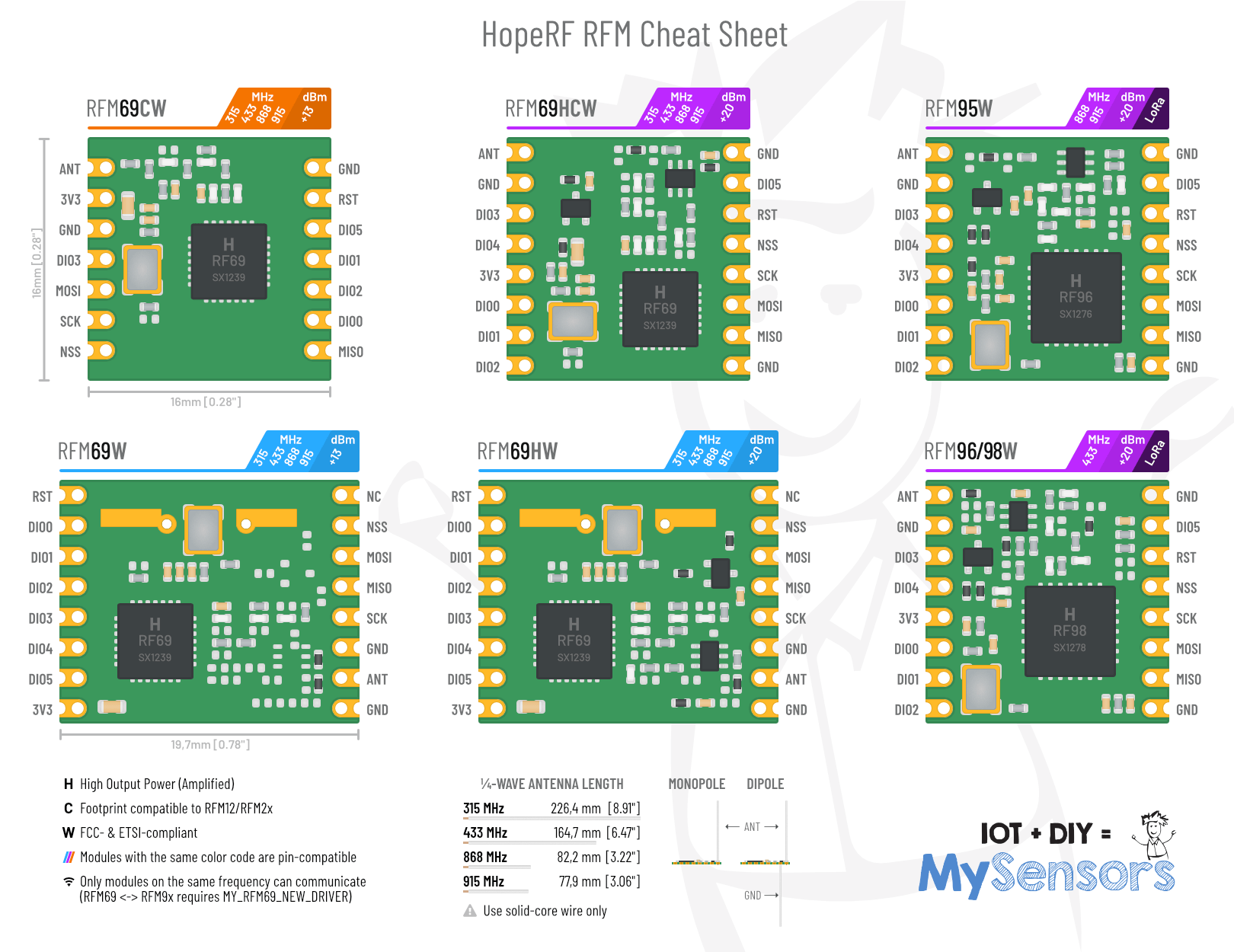
Since I already (half-heartedly) posted drawings of some RFM modules I created a while ago in another thread, I might as well put a little RFM69 / RFM9x infographic or cheat sheet together and share it with everyone. It's supposed to give beginners a quick overview over the available MySensors-compatible HopeRF modules.
If you guys mind that I included the MySensors logo and mascot, please let me know and I'll remove it ASAP.
-
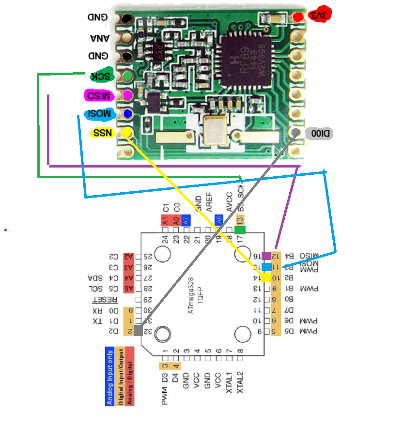
Connection diagram/circuit between RFM module and atmega328p-au TQFP footprint.
-
Connection diagram/circuit between RFM module and atmega328p-au TQFP footprint.
I would like to ask about the radio module connection - I am using SX1276 and I connect it the same way as described by @sundberg84 said in 💬 Connecting the Radio except I additionally connect also RST (NRESET) pin according to this https://github.com/sandeepmistry/arduino-LoRa/blob/master/README.md#semtech-sx1276777879-wiring
Is it necessary?
Thanks