💬 Building a Raspberry Pi Gateway


  • Mod

    Yes, I have both radios on the same raspberry.


  • More problems when I try to "make" after configuring. Tried with and without sudo...

    dietpi@Domoticz:~/MySensors$ sudo make
    gcc -MT build/hal/architecture/Linux/drivers/core/log.o -MMD -MP -march=armv6zk -mtune=arm1176jzf-s -mfpu=vfp -mfloat-abi=hard -DMY_SIGNING_SIMPLE_PASSWD=\"ZZZZZZZ\" -DMY_RADIO_RF24 -DMY_GATEWAY_LINUX -DMY_GATEWAY_MQTT_CLIENT -DMY_DEBUG -DLINUX_SPI_BCM -DLINUX_ARCH_RASPBERRYPI -DMY_LINUX_CONFIG_FILE=\"/etc/mysensors.conf\" -DMY_DEFAULT_TX_LED_PIN=18 -DMY_DEFAULT_RX_LED_PIN=16 -DMY_DEFAULT_ERR_LED_PIN=12 -DMY_MQTT_CLIENT_ID=\"mygateway1\" -DMY_MQTT_SUBSCRIBE_TOPIC_PREFIX=\"mysensors-in\" -DMY_MQTT_PUBLISH_TOPIC_PREFIX=\"mysensors-out\" -DMY_MQTT_PASSWORD=\"YYYYY\" -DMY_MQTT_USER=\"XXXX\" -DMY_CONTROLLER_IP_ADDRESS=127,0,0,1 -DMY_DEBUG_VERBOSE_SIGNING -DMY_RX_MESSAGE_BUFFER_FEATURE -DMY_RF24_IRQ_PIN=15  -Ofast -g -Wall -Wextra  -I. -I./core -I./hal/architecture/Linux/drivers/core -I./hal/architecture/Linux/drivers/BCM -c hal/architecture/Linux/drivers/core/log.c -o build/hal/architecture/Linux/drivers/core/log.o
    In file included from hal/architecture/Linux/drivers/core/log.c:20:0:
    hal/architecture/Linux/drivers/core/log.h:24:19: fatal error: stdio.h: File not found
     #include <stdio.h>
                       ^
    compilation terminated.
    Makefile:102: recipe for target 'build/hal/architecture/Linux/drivers/core/log.o' failed
    make: *** [build/hal/architecture/Linux/drivers/core/log.o] Error 1
    

    EDIT: ...and here's the fix: "sudo apt-get install g++" (I'm using DietPi now to make it lighter for Pi Zero W).


  • Running Version 2.3.2-beta just cloned today. On a raspberry pi B rev2.
    A little bug/problem I have discovered with the MQTT gateway.

    When you run the gateway with command and switch:-

    mysgw -c /etc/mysensors.conf
    

    It segfaults.

    When its run with the command and switch :-

    mysgw --config-file /etc/mysensors.conf
    

    It works fine

    I was playing with the ethernet gateway compile and the -c worked fine.


  • Another thing I have found is I cannot get any logging working with the mqqt gateway compile.

    It worked fine (named pipe) with the ethernet gateway compile.

    Edit
    It seems logging with the mqtt is not instant. It seem to dump the log out of memory periodically, is this expected? Makes it a bit hard to debug real-time.


  • Mod

    Just use mqtt client


  • Mod

    @coza I have experienced that the raspberry pigateway does not flush the logs immediately when logging to file. Syslog logs immediately though. See if switching to syslog helps.


  • @gohan Sorry I miss your answer a few days ago
    I don't want to a gateway with both rfm69 and nrf24..

    I'm planning to change my nrf24 sensors with rfm69, to have a better transmission distance. My two nodes are outside, and i have communication trouble if i put them where i wanted, specially for my rain gauge.
    So I wanted to use those adaptors https://www.openhardware.io/view/16/NRF2RFM69.
    I received them, and I'm still waiting RFM69 board to test it.

    But as the pinout is not the same between nrf24 and rfm69 on raspberry gateway, I could not use the adaptor on the gateway. So before making a new board for my raspberry, I wanted to know if it's possible to change the default pin configuration, to have exactly the same as nrf24, and use an adaptor on the gateway too.
    For that, I "just" need to redefine DIO0 on pin 15 (default is 22). So I wonder if it's possible to do it.

    And "bonus question", I'd like to know why pin configuration is not the same between arduino and raspberry. Why pin 15 is not used for DIO0 on raspberry (equivalent to pin 2 on arduino). I'm telling myself it should be a good reason, but I don't get it.


  • Mod

    @barrydou is this what you need (from the documentation and ./configure--help)

    --my-rfm69-irq-pin=<PIN>    Pin number connected to RFM69 IRQ pin.
    

    For the bonus question: I wasn't aware that there was a mapping between Raspberry Pi gpio and Arduino pins. Could you share he rest of the list?


  • @mfalkvidd I don't know what DI00 is, and if it's equivalent to IRQ ? If Yes, it's exactly what I need ! Thank you !!! 🙂 I will test it as soon as I get my RFM69

    Here is the pin mapping between RFM69W/NRF24 and Arduino/Raspberry

    Arduino mini - NRF24  - RFM69 - Raspberry GW NRF - Raspberry GW RFM 
    9            - CE     - N/A   - 22               - N/A
    10           - CSN/CS - NSS   - 24               - 24
    13           - SCK    - SCK   - 23               - 23
    11           - MOSI   - MOSI  - 19               - 19
    12           - MISO   - MISO  - 21               - 21
    2            - IRQ    - DI00  - 15               - 22
    

    So, the only mismatch breaking pin compatibility (and preventing to use adaptors on the raspberry pi gateway) is on IRQ/DI00. Adaptors wire RFM69 DI00 on NRF24 IRQ pin, but they don't use, by default, the same pin on raspberry, depending the radio type.


  • Mod

    @barrydou I don't know what dio0 is either, but https://learn.sparkfun.com/tutorials/rfm69hcw-hookup-guide/all describes it like this:

    Digital I/O 0
    RX interrupt Received data ready interrupt signal from RFM69HCW to microcontroller

    which sounds like it could be interrupt. It might be worth a try at least.


  • @mfalkvidd Thank you.
    I've found that too https://www.mysensors.org/apidocs/RFM69_8h_source.html
    It's clearly indicated that DIO0 is IRQ.

    So I think with "--my-rfm69-irq-pin=" it will do the job.

    I'll test it as soon as i'll receive RFM69.

    Thank you again


  • @marceloaqno Sorry to kick this old topic, but I will soon be trying to build my gateway with a Raspberry pi. I was wondering if the capacitor is also required for the gateway, or just for the nodes?

    Because at the instruction page on how to wire and build a Raspberry Pi gateway, the capacitor isn't mentioned.

    I'll be using a RPI 1 and NRF24L01+


  • Mod

    @rolandow yes the capacitor is needed. I'll add that info to the page. Thanks for noticing.


  • Ok, one more question. I thought I read somewhere that the wiring between the RPI and de radio should be as short as possible, but I can't find exactly where I read that anymore.

    At another project (zigbee2mqtt) I read that users had better reception when they placed the transceiver further away from the controller, because there was less inteference. So if possible, I would like to use a piece of UTP cable to wire the radio to the raspberry pi. That way I can put the rpi inside a closet, but the radio outside.

    So I am not sure if longer wires (say 2, 3 meters) is going to be a problem?


  • Mod

    @rolandow there could be a problem.

    There are two things to consider.

    1. Power drop due to resistance in the cable. See https://electronics.stackexchange.com/questions/113253/voltage-drop-and-safe-current-load-on-cat5-cable for details but use the current used by the radio (provided in the datasheet) instead of the 2.5A used in that question.

    2. SPI communication problems due to capacitance in the cable. See https://electronics.stackexchange.com/questions/163468/spi-max-distance for details. See also my post at https://forum.mysensors.org/post/92967 for oscilloscope pictures of what an i2c signal can look like through a long cable. SPI can handle longer cable lengts than i2c though.


    1. For me, my electronics is not as good as my development skills ;-). But I gave it a try. According to the datasheet the NRF24 will consume about 14 mA max. My cable is 2 m max, so then the resistance is 0,16ohms. So if I understand correctly the voltage drop would be 0,00224 volt. Sounds neglegtable to me? Also; can't I just measure the voltage at the end of the cable once it's connected to the RPI?

    2. At the stackoverflow page somebody says: "In an answer on a Microchip forum, Jan Axelson, author of 'Serial Port Complete', claims a maximum cable length of 10' for the SPI bus. Other posts have mentioned the same figure.". So 10" is about 3 metres, so I am within that range. I do understand though that this isn't a preferred thing to do.

    Which makes me wonder how other people handle this. I mean; I think ideally you'd want the radio that is connected to the controller in the most 'center' way of the home, right? So do people just hange the Pi and the whole shebang to the ceiling? 😉 I'd rather put the controller in the closet where my modem and router are, and then only wire the receiver to outside the closet. Isn't there a better way to do this?


  • Mod

    Nice work @rolandow
    You can measure the voltage drop, if you put a load of 14mA on the cable. But without load, there will be no voltage drop.

    One small adjustment on your calculation: there will be 4m cable (2m to the radio and 2m back). But the drop will still be negligable for a normal nrf24.


  • Please edit the image used in this tutorial:
    alt text
    It is wrong and misleading, as it says that pin36 is SPI1 CS0. In fact SPI1 CS0 by default is pin12. To be able to use pin36 as SPI1 CS0 one have to follow implicit steps which can be found on this forum thread: https://www.raspberrypi.org/forums/viewtopic.php?t=203776.
    Also it would be useful to add instructions to enable SPI1 in /boot/config.txt to the tutorial.


  • I want to run this gateway with another networkid (RFM69) but can't find how to do this. The option --my-rfm69-networkid=105 in the config line is ignored. So maybe it should go in the mysensnsors.conf file, but what is the syntax of this option?
    Thanks.


  • Mod

    @rolo6442u where did you find my-rfm69-networkid? I don't think such an option has ever existed. If you found it somewhere we probably need to update that documentation.

    Follow the instructions at https://www.mysensors.org/build/raspberry#advanced to set defines.


  • @mfalkvidd
    I did not found it, I kind of made it up, following the syntax of other options.
    Looks like there is no way of changing the ID at this moment for the PI gateway.


  • Mod

    @rolo6442u ok. Well, making things up will usually not add them to the code 😉

    There is a way. Two actually. Set the define in one of the two ways described on the link I provided.


  • @mfalkvidd
    Thanks, will take a look at that.


  • Is it also possible to read a sensor directly at the Raspberry Pi MQTT Gateway? I only want to send the status of a GPIO via MQTT. Is there an example code for this combination?


  • Plugin Developer

    Might be nice to know it compilation still seems to works fine on Raspbian Buster on a Raspberry Pi 4.

    // Update: unlike on the Pi 3 I now had to activate SPI. Might be good to make that more prominent in the explanation now.


  • Mod

    @alowhum to my knowledge, activating SPI has always been required, unless the user has already activated SPI by some other means.

    Do you have a suggestion on how to make it more prominent that what it is now? Preferably without contributing too much to the pileup of notices that scare users - everything is super-important to at least 1 person.


  • Plugin Developer

    @mfalkvidd I don't know, perhaps mention it as something that has to be done upfront instead of something that might need to be done if there is an error?

    I'm not having any luck actually getting the radio to work. I now noticed this warning during compilation:

    g++ -MT build/drivers/Linux/GPIO.o -MMD -MP -DMY_RADIO_RF24 -DMY_GATEWAY_LINUX -DMY_GATEWAY_MQTT_CLIENT -DMY_DEBUG -DLINUX_SPI_SPIDEV -DMY_MQTT_CLIENT_ID=\"mygateway1\" -DMY_MQTT_SUBSCRIBE_TOPIC_PREFIX=\"mysensors-in\" -DMY_MQTT_PUBLISH_TOPIC_PREFIX=\"mysensors-out\" -DMY_CONTROLLER_IP_ADDRESS=127,0,0,1  -Ofast -g -Wall -Wextra  -I. -I./core -I./drivers/Linux -c drivers/Linux/GPIO.cpp -o build/drivers/Linux/GPIO.o
    drivers/Linux/GPIO.cpp: In constructor ‘GPIOClass::GPIOClass()’:
    drivers/Linux/GPIO.cpp:53:18: warning: ‘%s’ directive writing up to 255 bytes into a region of size 48 [-Wformat-overflow=]
        sprintf(file, "/sys/class/gpio/%s/base", de->d_name);
                      ^~~~~~~~~~~~~~~~~~~~~~~~~
    drivers/Linux/GPIO.cpp:53:11: note: ‘sprintf’ output between 22 and 277 bytes into a destination of size 64
        sprintf(file, "/sys/class/gpio/%s/base", de->d_name);
        ~~~~~~~^~~~~~~~~~~~~~~~~~~~~~~~~~~~~~~~~~~~~~~~~~~~~
    drivers/Linux/GPIO.cpp:62:18: warning: ‘%s’ directive writing up to 255 bytes into a region of size 48 [-Wformat-overflow=]
        sprintf(file, "/sys/class/gpio/%s/ngpio", de->d_name);
                      ^~~~~~~~~~~~~~~~~~~~~~~~~~
    drivers/Linux/GPIO.cpp:62:11: note: ‘sprintf’ output between 23 and 278 bytes into a destination of size 64
        sprintf(file, "/sys/class/gpio/%s/ngpio", de->d_name);
        ~~~~~~~^~~~~~~~~~~~~~~~~~~~~~~~~~~~~~~~~~~~~~~~~~~~~~
    

  • Plugin Developer

    Could this be an issue?

    ./configure without any additional parameters gives:

    [SECTION] Detecting target machine.
      [OK] machine detected: SoC=unknown, Type=unknown, CPU=armv7l.
    

    The rest looks fine:

    [SECTION] Checking GPIO Sysfs.
      [OK] /sys/class/gpio/export found.
    [SECTION] Detecting SPI driver.
      [OK] SPI driver detected:SPIDEV.
    [SECTION] Gateway configuration.
      [OK] Type: ethernet.
      [OK] Transport: rf24.
      [OK] Signing: Disabled.
      [OK] Encryption: Disabled.
      [OK] CPPFLAGS: -DMY_RADIO_RF24 -DMY_GATEWAY_LINUX -DMY_DEBUG -DLINUX_SPI_SPIDEV 
    [SECTION] Detecting init system.
      [OK] Init system detected: systemd.
    [SECTION] Saving configuration.
      [OK] Saved.
    [SECTION] Cleaning previous builds.
      [OK] Finished.
    

    Same thing happens with the dev version


  • Mod

    Yes, if the configure script cannot detect which hardware to use, compilation failure could very well be the result.


  • Hi All

    I'm just venturing into this world of building my own sensors - but perhaps i am a tad late? Two months since last update.. Typically me - showing up to the party when everybody else has left.

    My main issue is, i am running the Raspberry Pi 4 - and when trying to build (i've tried both the development and master builds) i get from 4 (master build) to A BUNCH (development) of errors. First of all, the autodetect of SoC does not work for me either (just like @alowhum, and with the same warnings), and when using --help the actual SoC is not listed either, so should i just assume it does not work for Raspberry Pi 4?

    Is there any chance the 4 will be supported soon?

    Just a note - i can actually complete the configure and then make - but unfortunately i just get a TSP error when trying to fire up the radio.

    Hope i can get this working as it was the main reason for upgrading my RaspberryPi version 1 to a version 4 🤦‍♂️

    Thanks in advance for any and all help!


  • Mod

    Thanks for sharing your experience @swedchef

    From the problems reported by users (you included), it seems like the rpi4 is quite different fom the earlier rpis. To add support, the following ingredients are needed in one person

    • person needs to have sufficient knowledge and skills to figure out how to support the rpi4
    • person needs to have sufficient time to do the work
    • person needs to have a rpi4
    • person needs to be sufficiently interested/motivated to do the work

    It seems like, so far, we haven't found this person (or this person hasn't found us).


  • Re: 💬 Building a Raspberry Pi Gateway

    Hi all,

    i compile with success the gateway in Raspberry PI 4 (with some code modification)

    this is not perfect.. but it works.

    if someone wants to try, i upload the gateway compiled with this options :

    --my-transport=rf24 --my-gateway=ethernet --my-port=5003
    

    https://gofile.io/?c=fRxeF7


  • Contest Winner

    @phildefer could you please share what you changed? The security concerned might not be comfortable running a binary with unspecified changes that manages their home automation setup. Especially not a project supposed to be open source.


  • Mod

    @phildefer would you mind sharing the code modifications that were needed?


  • @mfalkvidd @Anticimex : yes i sharing the code perhaps this week end. I need to find time to make a PR to GITHUB
    As I said, my code may not be as clean as you'd like, but it works.


  • Hey all,

    I got the same problem as @swedchef and saw the warnings @alowhum mentioned.
    Simply upping the buffer that is declared in GPIO.cpp solved the warnings and made it compile without issue but the radio still won't work.
    Maybe it has to do with the soc not being detected, as mentioned, and that the pin positions on the new soc are different from previous ones.

    @phildefer, weekend has come and gone buddy. Patience is a virtue some do not have. 🙂

    Edit: So looking a little more through the files today i see that configure looks for the soc type in /proc/cpuinfo and funnily my raspi 4 reports a BCM2835


  • Mod

    @patrikr76 I beleive @phildefer pushed the code 4 days ago. See https://github.com/mysensors/MySensors/pull/1353

    Something has seriously mangled whitespace in the modified code, but apart from that it looks good to me, but I am not that familiar with the rpi code and I have not tested it myself.


  • @mfalkvidd said in 💬 Building a Raspberry Pi Gateway:

    @patrikr76 I beleive @phildefer pushed the code 4 days ago. See https://github.com/mysensors/MySensors/pull/1353

    You are correct.
    @phildefer, thank you.
    There were a couple of minor warnings about indentations and the buffer size i mentioned earlier fixed by upping the declared buffer in GPIO.cpp. Not sure if that is a good fix or not, the warning goes away though.
    A few other warnings looks like this:

    In member function ‘char* MyMessage::getString(char*) const’,
        inlined from ‘bool transportSendWrite(uint8_t, MyMessage&)’ at ./core/MyTransport.cpp:987:2,
        inlined from ‘bool transportRouteMessage(MyMessage&)’ at ./core/MyTransport.cpp:560:40,
        inlined from ‘void stUplinkTransition()’ at ./core/MyTransport.cpp:252:29:
    ./core/MyMessage.cpp:284:17: warning: ‘char* strncpy(char*, const char*, size_t)’ output may be truncated copying between 0 and 25 bytes from a string of length 25 [-Wstringop-truncation]
        (void)strncpy(buffer, this->data, this->getLength());
              ~~~~~~~^~~~~~~~~~~~~~~~~~~~~~~~~~~~~~~~~~~~~~~
    

    Not sure how to fix those.

    Edit: Forgot to mention, it seems to be working though.


  • Thanks guys for the effort to port MySensors for the Pi 4.

    I'm very interested, but my coding skills are not sufficient to help in the development. Maybe I can do some debug when my Pi4 will arrive

    MySensors for the Pi4 is a must-have!😊


  • @mfalkvidd @phildefer

    I can confirm that the code compiles and runs on my rasbperry pi 4 model b. I am using a rfm69 radio and that seems to be working too. I couldn't test it yet though since I haven't wired any rfm69 nodes up yet.


  • @kiesel Good news!😉
    I will test both (nrf24 and rfm69) when my Pi 4 arrive.


  • Ok my Pi 4 is arrived. I have 2 gateway, one RFM69 and one NRF24 connected respectively to spi0 and spi1. Details here.

    With a Raspberry Pi 3 all works fine (compilation and execution) with both Rasbian Stretch and with Raspbian Buster.

    With a Raspberry Pi 4 and the same version of Rasbian Buster the situation is a bit different:

    • The RFM69 gateway on the SPI0 compiles and can be executed without problems. In this days I don't have an RFM69 radio module, so I don't know if it works, but the daemon start in a regular way.

    • The NRF24 gateway compile, but after few seconds of execution the daemon stops with the following error.

    Oct 26 13:59:47 ERROR Could not open /sys/class/gpio/gpio12/direction
    

    Considering that the same configuration works for a Pi 3, it is possible that the error is caused by the autodetect of SoC issue mentioned above?

    The details of my /boot/config.txt file are here


  • Update:

    • tested the RFM69 gateway with a radio module attached -> Not working

    • tried to compile and execute the NRF24 gateway on the first spi bus (--spi-spidev-device=/dev/spidev0.0) -> same error as above

    ERROR Could not open /sys/class/gpio/gpio12/direction
    

    I have checked my Makefile and configure files and they don't contain the modification proposed by @phildefer . Is this normal? I'm using the development branch.


  • Tested with this commit of @phildefer, now both gateways compiles and starts but for both I got this error.

    Oct 27 20:50:41 DEBUG !TSM:INIT:TSP FAIL


  • Hi, if someone needs more info (debug, log, etc...) I'm here.

    I can perform tests on Rpi 3 and Rpi 4 (Raspbian Buster) with NRF24 and RFM69 radio modules and then report the results. Not so much but maybe this can help the development.


  • I'm doing a brand new install of Openhab2 and the mysensors gateway on a new Raspberry Pi 4 after having run Openhab(1) and the mysensors gateway successfully on a Raspberry Pi 3 for years. I used the development branch of the mysensorsgateway as discussed here: https://github.com/mysensors/MySensors/pull/1364

    I wrote down my step by step procedure here in case it helps someone else. I'm starting out with the pre-built Openhabian image found here: https://www.openhab.org/docs/installation/openhabian.html

    Install the PiGatewaySerial using these instructions:

    1. First get to your Downloads directory
    cd
    cd Downloads
    
    1. Clone the MySensors repository into your Downloads directory and then go into that folder
    git clone https://github.com/mysensors/MySensors.git --branch development
    cd MySensors
    
    1. Set configuration options (you can use “./configure —help” to see your options)
      a. In this case we are choosing to use the serial gateway with a pseudo terminal and a symbolic link to that pseudoterminal called ttyUSB20 in /dev. We then set the group to tty.
    ./configure --my-gateway=serial --my-serial-is-pty --my-serial-pty=/dev/ttyUSB20 --my-serial-groupname=tty
    

    Edit: If building this on a 64bit operating system you will need to edit the configure file before running make. Do the following:

    cp configure configure_bk
    nano configure
    

    Find this function

    function gcc_cpu_flags {
        local soc=$1
        case $soc in
    

    and find your CPU. In my case it is the BCM2711 (I've only done this on this one CPU so your mileage may vary) and I changed this:

     BCM2711)
            flags="-march=armv8-a+crc -mtune=cortex-a72 -mfpu=neon-fp-armv8 -mfloat-abi=hard"
    

    to this:

    BCM2711)
            flags="-march=armv8-a+crc -mtune=cortex-a72"
    

    Then proceed to step 4 below.

    1. Run make and make install
    make
    sudo make install
    
    1. We can set it to launch on boot up by running
    sudo systemctl enable mysgw.service
    
    1. To launch it manually right now run (skip this step to run and see output for confirmation that it works)
    sudo systemctl start mysgw.service
    
    1. Executable in located:
    cd /usr/local/bin
    
    1. need root to run it:
    sudo mysgw
    

    That's pretty much it. I was happily greeted with:

    Dec 29 16:01:50 INFO Starting gateway...
    Dec 29 16:01:50 INFO Protocol version - 2.4.0-alpha
    Dec 29 16:01:50 DEBUG Serial port /dev/ttyUSB20 (115200 baud) created
    Dec 29 16:01:50 DEBUG MCO:BGN:INIT GW,CP=RNNGL---,FQ=NA,REL=0,VER=2.4.0-alpha
    Dec 29 16:01:50 DEBUG TSF:LRT:OK
    Dec 29 16:01:50 DEBUG TSM:INIT
    Dec 29 16:01:50 DEBUG TSF:WUR:MS=0
    Dec 29 16:01:50 DEBUG TSM:INIT:TSP OK
    Dec 29 16:01:50 DEBUG TSM:INIT:GW MODE
    Dec 29 16:01:50 DEBUG TSM:READY:ID=0,PAR=0,DIS=0
    Dec 29 16:01:50 DEBUG MCO:REG:NOT NEEDED
    Dec 29 16:01:50 DEBUG MCO:BGN:STP
    Dec 29 16:01:50 DEBUG MCO:BGN:INIT OK,TSP=1
    Dec 29 16:01:50 DEBUG TSM:READY:NWD REQ
    Dec 29 16:01:50 DEBUG ?TSF:MSG:SEND,0-0-255-255,s=255,c=3,t=20,pt=0,l=0,sg=0,ft=0,st=OK:
    Dec 29 16:01:50 DEBUG TSF:MSG:READ,4-4-0,s=255,c=3,t=21,pt=1,l=1,sg=0:0
    Dec 29 16:01:50 DEBUG TSF:MSG:READ,0-4-255,s=255,c=3,t=20,pt=0,l=0,sg=0:
    Dec 29 16:01:50 DEBUG TSF:MSG:BC
    Dec 29 16:01:52 DEBUG TSF:MSG:READ,4-4-0,s=1,c=1,t=2,pt=2,l=2,sg=0:0
    Dec 29 16:01:52 DEBUG TSF:MSG:READ,4-4-0,s=2,c=1,t=2,pt=2,l=2,sg=0:0
    Dec 29 16:01:52 DEBUG TSF:MSG:READ,4-4-0,s=3,c=1,t=2,pt=2,l=2,sg=0:1
    Dec 29 16:01:52 DEBUG TSF:MSG:READ,4-4-0,s=4,c=1,t=2,pt=2,l=2,sg=0:1
    ^CDec 29 16:02:35 NOTICE Received SIGINT


  • Be advised that there seems to be an issue with rfm69HW on the raspberry pi:

    When using the radio directly on the pi (not as a serial gateway) the range drops significantly:

    https://github.com/mysensors/MySensors/issues/1367

    Apparently this wasn't an issue with mysensors 2.2, so using that is an option if you can compile it for you raspberry pi.


  • I'm getting a bad file descriptor error, any advice? Seems only 1 instance to be running.

    pi@raspberrypi:~ $ sudo mysgw
    Mar 19 20:14:04 INFO  Starting gateway...
    Mar 19 20:14:04 INFO  Protocol version - 2.3.2
    Mar 19 20:14:04 DEBUG MCO:BGN:INIT GW,CP=RNNGL---,FQ=NA,REL=255,VER=2.3.2
    Mar 19 20:14:04 DEBUG TSF:LRT:OK
    Mar 19 20:14:04 DEBUG TSM:INIT
    Mar 19 20:14:04 DEBUG TSF:WUR:MS=0
    Mar 19 20:14:04 DEBUG TSM:INIT:TSP OK
    Mar 19 20:14:04 DEBUG TSM:INIT:GW MODE
    Mar 19 20:14:04 DEBUG TSM:READY:ID=0,PAR=0,DIS=0
    Mar 19 20:14:04 DEBUG MCO:REG:NOT NEEDED
    Mar 19 20:14:04 ERROR bind: Address already in use
    Mar 19 20:14:04 ERROR Failed to bind!
    Mar 19 20:14:04 DEBUG MCO:BGN:STP
    Mar 19 20:14:04 DEBUG MCO:BGN:INIT OK,TSP=1
    Mar 19 20:14:04 ERROR accept: Bad file descriptor
    Mar 19 20:14:04 ERROR accept: Bad file descriptor
    Mar 19 20:14:04 ERROR accept: Bad file descriptor
    Mar 19 20:14:04 ERROR accept: Bad file descriptor
    Mar 19 20:14:04 ERROR accept: Bad file descriptor
    Mar 19 20:14:04 ERROR accept: Bad file descriptor
    Mar 19 20:14:04 ERROR accept: Bad file descriptor
    Mar 19 20:14:04 ERROR accept: Bad file descriptor
    Mar 19 20:14:04 ERROR accept: Bad file descriptor
    Mar 19 20:14:04 ERROR accept: Bad file descriptor
    Mar 19 20:14:04 DEBUG TSM:READY:NWD REQ
    Mar 19 20:14:04 DEBUG ?TSF:MSG:SEND,0-0-255-255,s=255,c=3,t=20,pt=0,l=0,sg=0,ft=0,st=OK:
    Mar 19 20:14:04 ERROR accept: Bad file descriptor
    Mar 19 20:14:04 ERROR accept: Bad file descriptor
    Mar 19 20:14:04 ERROR accept: Bad file descriptor
    Mar 19 20:14:04 ERROR accept: Bad file descriptor
    Mar 19 20:14:04 ERROR accept: Bad file descriptor
    

  • Mod

    @Sebex don't run multiple instances that try to listen to the same tcp port.


  • @mfalkvidd thanks, I was wrongly under the impression that sudo mysgw would show the logs but it creates a second instance. Thanks for helping 😄!


  • I have an Arduino Mesh network (see https://tmrh20.github.io/RF24Mesh/) (master and 4 nodes)
    networkChannel 120, networkDataRate RF24_1MBPS, nodes 0-4

    Now I want to have my master be an RPi because it can talk to the real world.

    It looks like I have the RPi wired up and software loaded (per https://www.mysensors.org/build/raspberry). Now I need to know how to talk to my Arduino's.

    Now how do I talk to my Arduino's?

    o- general description of what you are trying to do
    Raspberry Pi controller with serial gateway with nrf24l01+ to connect to Arduino's
    o- the exact configure command you used
    git clone https://github.com/mysensors/MySensors.git --branch master
    cd MySensors
    ./configure --my-transport=rf24 --my-gateway=serial --my-serial-is-pty --my-serial-port=/dev/ttyMySensorsGateway
    make
    sudo ./bin/mysgw
    [reboot RPi]
    cd MySensors
    sudo make install
    sudo systemctl enable mysgw.service
    sudo systemctl start mysgw.service
    ls -als /dev/ttyMySensorsGateway [yeilds: 0 lrwxrwxrwx 1 root root 10 Apr 9 19:22 /dev/ttyMySensorsGateway -> /dev/pts/1]

    o- the output from the test
    Apr 09 18:47:32 INFO Config file /etc/mysensors.conf does not exist, creating new file.
    Apr 09 18:47:32 INFO Starting gateway...
    Apr 09 18:47:32 INFO Protocol version - 2.3.2
    Apr 09 18:47:32 DEBUG Serial port /dev/ttyMySensorsGateway (115200 baud) created
    Apr 09 18:47:32 INFO EEPROM file /etc/mysensors.eeprom does not exist, creating new file.
    Apr 09 18:47:32 DEBUG MCO:BGN:INIT GW,CP=RNNGL---,FQ=NA,REL=255,VER=2.3.2
    Apr 09 18:47:32 DEBUG TSF:LRT:OK
    Apr 09 18:47:32 DEBUG TSM:INIT
    Apr 09 18:47:32 DEBUG TSF:WUR:MS=0
    Apr 09 18:47:32 DEBUG TSM:INIT:TSP OK
    Apr 09 18:47:32 DEBUG TSM:INIT:GW MODE
    Apr 09 18:47:32 DEBUG TSM:READY:ID=0,PAR=0,DIS=0
    Apr 09 18:47:32 DEBUG MCO:REG:NOT NEEDED
    Apr 09 18:47:32 DEBUG MCO:BGN:STP
    Apr 09 18:47:32 DEBUG MCO:BGN:INIT OK,TSP=1
    Apr 09 18:47:32 DEBUG TSM:READY:NWD REQ
    Apr 09 18:47:32 DEBUG ?TSF:MSG:SEND,0-0-255-255,s=255,c=3,t=20,pt=0,l=0,sg=0,ft=0,st=OK:
    [did not return to command prompt]
    o- the settings you used in your controller
    n/a


  • Mod

    @OldSurferDude if you want your nodes to use MySensors, you'll need to upload MySensors sketches to them.


  • hi i am trying to install an MQTT type gateway on a raspberry pi 3,
     
    I configured it as in the example:

    ./configure --my-gateway = mqtt --my-controller-ip-address = 127.0.0.1 --my-mqtt-publish-topic-prefix = mysensors-out --my-mqtt-subscribe-topic-prefix = mysensors-in --my-mqtt-client-id = mygateway1

    Then I do make and it does not generate errors.

    and when i run

    sudo mysgw

    returns the following result, I do not understand what it can be or what it means.

    Apr 10 15:12:21 DEBUG connected to 127.0.0.1
    Apr 10 15:12:22 DEBUG! GWT: RMQ: FAIL
    Apr 10 15:12:22 DEBUG GWT: RMQ: CONNECTING ...
    Apr 10 15:12:22 DEBUG connected to 127.0.0.1
    Apr 10 15:12:23 DEBUG! GWT: RMQ: FAIL
    Apr 10 15:12:23 DEBUG GWT: RMQ: CONNECTING ...
    Apr 10 15:12:23 DEBUG connected to 127.0.0.1

    I appreciate your time to explain this to me please, I am just starting to use Mysensors and it is incredible everything that can be generated.

    Also I want to connect it to Mycontrroller.org to manage my devices from my sensor network with only 1 Gateway, I already downloaded it in my RPI3 and it runs fine, but when I connect or create the mqtt type gateway, it asks me for the broker host and I do not know what to put there, I thought of 127.0.0.1, but after that it tells me that the State is down and an error message with the IP of 127.0.0.1 and I do not know then that I need this. Thanks again for your time to explain this to you.


  • You're not being able to connect to your MQTT broker (Mosquitto or Moqutte as was in mycontroller.org). I havent used mycontroller so I cant help with that.

    I use Mosquitto on the same Rpi (so just install mosquitto and mosquitto-clients). You should secure it but test first without credentials to get going. Remember to create credentials in mosquitto AND reconfig your gw


  • @MasMat I already managed to configure my gateway it already works with Mycontroller.org, I like the interface of this, but I was thinking if the nodes of my network, which are esp8266 can be configured an operating system like FreeRTOS, TinyOS or ApacHE MyNewt can be configured in my osp and handle all Mysensors processes?
    There is a possibility or it is impossible


  • @Nicolás-Potier that's way way over my understanding and fluency with Mysensors. And way off topic, I think.


  • Hi all,

    I want to launch gateway on RaspberryPi with a RS485 network.
    I downloaded the software (MySensors Library v2.4.0-alpha).
    And i made coniguration:
    ./configure --my-transport=rs485 --my-rs485-serial-port=/dev/ttyUSB0 --my-rs485-baudrate=9600 --my-gateway=serial --my-serial-is-pty --my-serial-port=/dev/ttyUSB20 -my-serial-baudrate=115200 -my-serial-groupname=tty

    I have USB-RS485 (it uses FT232RL) converter connected to the /dev/ttyUSB0.
    On the other side i have Arduino uno with UART-RS485 (MAX485) converter, and a MotionSensorRS485 example on it.

    After i made the program (make), and type sudo ./bin/mysgw, i've got this:
    8e71edb2-f77b-46c9-8a6b-929527fda8a8-image.png

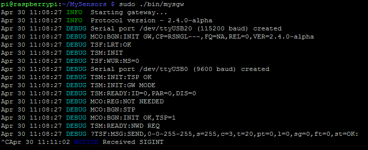
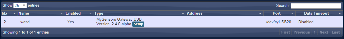
    I'm able to add the hardware in domoticz (serial gateway ttyYSB20, 115200), but it doesn't see nodes.
    bbb6c72d-87cf-4e50-95f0-a0501174bfe3-image.png

    Please help.


  • Mod

    @rafal9318 please don't post the same question in multiple threads. Posting in multiple threads means the discussion is split. Important information might be available in one thread, but not the other, which means people have to ask you for that information multiple times. It is a waste of the community members' (including you) time.

    If anyone can help @rafal9318 please respond in https://forum.mysensors.org/topic/11128/raspberrypi-4-as-a-gateway-controller


  • @mfalkvidd Okey, sorry.


  • I’m sorry if this is a newbie question. I have managed to create a controller using MyController on a Raspberry Pi. I have connected a NRF24l01 and created a gateway, and my controller picks up that I have a gateway present, so I assume my wiring is correct.
    I have started to wire up the status LEDs, and this is where I am confused. I am used to using LEDs on PI, but connecting between he GPIO pin and ground, where the GPIO provides the voltage. The diagram above suggests that they should be permanently connected to the voltage and the GPIO provides the ground connection. Is this correct? And if it is, is it possible to test the LEDs? Thanks in advance.


  • @ej3-martin My LEDs come on when the Rpi boots (is that what you mean by testing?). Also you can invert the LEDs (on but blink off) if you want. I figured the wiring makes for better power delivery rather than feeding voltage from the GPIO


  • @MasMat I was purely wanting to find a way of testing them, to check my wiring, if they do come on during boot then this is a great way to test. It would also possibly be useful (for those of us less experienced) to have a script to run to check the wiring is correct. I think it much more useful to have them off, and blink on, and it was the wiring that confused me. I will have to see if I can investigate this further.


  • Mod

    Since the pins are configurable before compilation, creating a script that uses the same settings as the compiled code would be pretty hard.

    The easiest way with existing code is probably to add --my-leds-blinking-inverse to your configure command and start the gateway, as suggested by @MasMat


  • Just trying to figure out whether there is a switch or config file option for the channel, or whether the only option to change the channel is truly to recompile?!...

    Just ran the Poor Man's scanner and channels 1-98 a a garbage mess, so I need to go >> 100, but am surprised the only option there seems to be a recompile?...


  • Mod

    @Fear-na-Boinne yes that is correct


  • Sorry for the lack of response, life's been crazy... Thanks for the reply, I have since recompiled, but need to make some add'l changes to the sensor sketches, so I want to do all of that at once before I deploy to the new channel... 😉


  • Mod

    @Fear-na-Boinne if you want to be able to switch your rpi gateway between the old and the new channel while testing, you could try my patch which allows configurable service name

    https://github.com/mysensors/MySensors/pull/1421

    Or just skip running make install so you don’t overwrite the old gateway


  • @mfalkvidd Just a quick update...

    Been extremely busy, so not a lot of time, but when I run the recompiled version (channel 109) gateway and use the existing - known good - sensor sketches with the channel 109 macro declaration included, it doesn't connect at all.
    When I run the "old" version of the gateway and the same sensor sketches with channel 109 commented out, it just-works™...

    More testing and such due I guess! 😞


  • Is it possible to have the RPi4B, that is being used as the Webthings Gateway, also be the My Sensor controller once I add a NRF24L01+ module and follow steps above?


  • To clarify, I have the Mozilla Webthings Controller and I want to know if I can use the instructions above to make the same RPi4B to be the MySensors gateway. Any help would be greatly appreciated.


  • In case someone has similar issue:
    Running everything latest up to date.

    Raspberry pi zero w with nrf24 connected directly on GPIO and domoticz. Had to have startup delay on mysgw service since domoticz wouldn't or couldn't start automatically on boot.
    So i added to:
    sudo nano /etc/systemd/system/mysgw.service

    [Service]
    ExecStartPre=/bin/sleep 10

    Maybe 10 seconds is overkill, but at least it works now.
    With raspberry pi 3b+ there wasn't that issue.

    Also in domoticz had to use raspi ip address, when setting up mysensors LAN gateway address, instead of localhost 127.0.0.1

    And myscontroller OTA updates are working too.🙂


  • I'm new to MySensors. I'm trying to build an MQTT gateway with an nRF24 radio on my RPi 3B+. I follow the instructions here,
    My radio is connected with CE on physical pin 15 (GPIO22) and CSN on physical pin 24 (GPIO8) I am confident this works has I was able to run the tMRH20 examples

    I follow the instructions here on this web page

    I configured with:

    ./configure --my-gateway=mqtt --my-controller-ip-address=127.0.0.1 --my-mqtt-publish-topic-prefix=mysensors-out --my-mqtt-subscribe-topic-prefix=mysensors-in --my-mqtt-client-id=mygateway1 --my-transport=rf24
    

    I run make but quickly error with "missing stropts.h" for which I found a fix "sudo touch /usr/include/stropts.h". I run make again after a many warnings it stops with Error 1. The last few lines:

    re/Linux/drivers/core/compatibility.o build/hal/architecture/Linux/drivers/core/EthernetClient.o build/hal/architecture/Linux/drivers/core/EthernetServer.o build/hal/architecture/Linux/drivers/core/GPIO.o build/hal/architecture/Linux/drivers/core/interrupt.o build/hal/architecture/Linux/drivers/core/IPAddress.o build/hal/architecture/Linux/drivers/core/noniso.o build/hal/architecture/Linux/drivers/core/Print.o build/hal/architecture/Linux/drivers/core/SerialPort.o build/hal/architecture/Linux/drivers/core/SoftEeprom.o build/hal/architecture/Linux/drivers/core/SPIDEV.o build/hal/architecture/Linux/drivers/core/StdInOutStream.o build/hal/architecture/Linux/drivers/core/Stream.o build/examples_linux/mysgw.o build/hal/architecture/Linux/drivers/BCM/bcm2835.o build/hal/architecture/Linux/drivers/BCM/BCM.o build/hal/architecture/Linux/drivers/BCM/RPi.o build/hal/architecture/Linux/drivers/BCM/SPIBCM.o build/hal/architecture/Linux/drivers/BCM/Wire.o 
    /usr/bin/ld: build/examples_linux/mysgw.o: in function `.LANCHOR1':
    /home/appian3344/MySensors/./hal/architecture/Linux/drivers/core/config.h:39: multiple definition of `conf'; build/hal/architecture/Linux/drivers/core/config.o:/home/appian3344/MySensors/hal/architecture/Linux/drivers/core/config.h:39: first defined here
    collect2: error: ld returned 1 exit status
    make: *** [Makefile:80: bin/mysgw] Error 1
    

    OK, what didn't I do right?


  • Mod

    @OldSurferDude loos like it could be the same problem as https://github.com/mysensors/MySensors/pull/1454

    In that case, applying the suggested fix manually, or using the development branch (where the fix is already included) should work.


  • @mfalkvidd I implemented your suggestion of running the development branch. This didn't work for a different reason. Below my questions is what I did.
    Questions:
    o Is the gateway trying to connect to a controller such as Home Assistant (HA)?
    o The IP address of 127.0.0.1 implies the controller is on the same machine. Would the gateway connect to a docker containerized HA?
    o What example programs will connect to the RF24 radio side of the gateway? We could start off with a simple ONoff switch and progress to that node controlling a relay on another node. (passing the request through an MQTT broker?)
    o Note that I made the assumption that the gateway doesn't distinguish between wired ethernet or WiFi. Is that a good assumption?

    Hardware RPi 3B+, nRF24 wired with CE to physical pin 15
    OS: Raspbian GNU/Linux 11 (bullseye)

    It is assumed that deleting the MySensors folder will uninstall the existing master branch. (probably a bad assumption)

    1. sudo rm -r MySensors

    2. git clone https://github.com/mysensors/MySensors.git --branch development

    3. cd MySensors

    4. ./configure --my-gateway=mqtt --my-controller-ip-address=127.0.0.1 --my-mqtt-publish-topic-prefix=mysensors-out --my-mqtt-subscribe-topic-prefix=mysensors-in --my-mqtt-client-id=mygateway1 --my-transport=rf24
      note: It is stated that the default configuration is ethernet port 5003 (./configure --my-gateway=ethernet --my-port=5003)
      It is assumed that the software doesn't distinguish between ethernet and WiFi

    5. make
      many compiler warnings

    6. Start gateway with
      sudo ./bin/mysgw

      which results in:

      Apr 04 12:12:37 INFO Config file /etc/mysensors.conf does not exist, creating new file.
      Apr 04 12:12:37 INFO Starting gateway...
      Apr 04 12:12:37 INFO Protocol version - 2.4.0-alpha
      Apr 04 12:12:37 INFO EEPROM file /etc/mysensors.eeprom does not exist, creating new file.
      Apr 04 12:12:37 DEBUG MCO:BGN:INIT GW,CP=RNNGL---,FQ=NA,REL=0,VER=2.4.0-alpha
      Apr 04 12:12:37 DEBUG TSF:LRT:OK
      Apr 04 12:12:37 DEBUG TSM:INIT
      Apr 04 12:12:37 DEBUG TSF:WUR:MS=0
      Apr 04 12:12:37 DEBUG TSM:INIT:TSP OK
      Apr 04 12:12:37 DEBUG TSM:INIT:GW MODE
      Apr 04 12:12:37 DEBUG TSM:READY:ID=0,PAR=0,DIS=0
      Apr 04 12:12:37 DEBUG MCO:REG:NOT NEEDED
      Apr 04 12:12:37 DEBUG MCO:BGN:STP
      Apr 04 12:12:37 DEBUG MCO:BGN:INIT OK,TSP=1

      followed by repeating:

      Apr 04 12:12:37 DEBUG GWT:RMQ:CONNECTING...
      Apr 04 12:12:37 ERROR connect: Connection refused
      Apr 04 12:12:37 ERROR failed to connect
      Apr 04 12:12:38 DEBUG !GWT:RMQ:FAIL
      Apr 04 12:12:38 DEBUG TSM:READY:NWD REQ
      Apr 04 12:12:40 DEBUG ?TSF:MSG:SEND,0-0-255-255,s=255,c=3,t=20,pt=0,l=0,sg=0,ft=0,st=OK:

    Assumed that it failed to connect to an MQTT broker and the my-controller-ip-address is a broker address

    Changed the --my-controller-ip-address to that of my MQTT broker (It is assumed that the default MQTT port is used)
    repeat step 4. with the change and step 5. and 6.
    no joy same output
    Restarted with step 1 with changes
    no joy same output


  • Mod

    @OldSurferDude said in 💬 Building a Raspberry Pi Gateway:

    o Is the gateway trying to connect to a controller such as Home Assistant (HA)?

    Yes, a controller or a mqtt broker.

    o The IP address of 127.0.0.1 implies the controller is on the same machine. Would the gateway connect to a docker containerized HA?

    I think it depends on how the docker is set up, but I don't have enough knowledge about docker to say for sure.

    o What example programs will connect to the RF24 radio side of the gateway? We could start off with a simple ONoff switch and progress to that node controlling a relay on another node. (passing the request through an MQTT broker?)

    You could build any of the nodes on the build page, or use https://github.com/mysensors/MySensors/tree/development/examples/MockMySensors or just create a local sensor on the gateway (if you don't need to test the nrf24 communication).

    o Note that I made the assumption that the gateway doesn't distinguish between wired ethernet or WiFi. Is that a good assumption?

    In the case of the Raspberry Pi gateway yes. It will use the Pi's networking, regardless of type.


  • @OldSurferDude I don't see a password in your configure settings. Since it is saying that the connection is refused from your MQTT broker, that was the first thing that popped out to me. Do you have access control set up on the broker? I'm assuming that you have the IP address and port set up correctly.

    I'm not sure if there would be a different message for other things, but when I had the access control on and messed up the username or password it would tell me connection refused or at least something very similar.


  • @ejlane @mfalkvidd

    I installed an MQTT broker on another linux machine. I did not set up access control(username, password) If I install mosquitto-clients I can pub/sub to the broker without username and password. In addition, on my windows box, I installed MQTT Explorer and can monitor the broker, again without username and password. (should I specify --my-mqtt-user="" and --my-mqtt-password=""?)

    I have HA on the RPi. I can access it on my windows box with http://192.168.sss.sss:8123. It requires a user password. but I don't see any parameter that refers to a password for an ethernet controller.

    I'll try those programs, but first I think I need to get MySensors working.

    Has anyone developed a cookbook? http://tmrh20.github.io/ has many examples of using the RF24 with combinations of RPi and Arduinos. These examples start with very basic connection to very complex. I built a for Arduino Nodes, 1 RPi master system that has been running well for two years. But I decided I need MQTT to exchange data with other devices. Alas, the MQTT client example works, but the computational load on the Arduino was too much and therefore unusable.

    I'm looking to MySensors because it appears that the computational load for sensor nodes is tolerable. and it appears to have an MQTT gateway.

    Cookbook? working examples?


  • @ejlane @mfalkvidd

    A bit more thrashing and found that I would need an integration set up on HA.

    I tried a TCP connection and HA could not connect. I then then set up a TCP configuration on MS (./configure --my-transport=rf24 --my-gateway=ethernet --my-controller-ip-address=127.0.0.1) and while it was streaming error messages, I tried to connect HA.

    The I tried an HA/MS connecting using MQTT at address 127.0.0.1 but HA failed to connect (you have to install the HA MQTT integration before installing the HA MS integration.) With the same ip address on the MS configuration (./configure --my-transport=rf24 --my-gateway=mqtt --my-controller-ip-address=127.0.0.1 --my-mqtt-publish-topic-prefix=mysensors-out --my-mqtt-subscribe-topic-prefix=mysensors-in --my-mqtt-client-id=mygateway1) still failed to connect,

    Some joy was found when I set the ip address to that of my MQTT broker. Neither HA nor MS reported any error messages.

    OK, now onto the Arduino side of things.

    OSD


  • @ejlane @mfalkvidd

    On the RPi: MySensors and running HA in a docker container. Another linux box is running the MQTT broker. MQTT Explorer is running on a windows PC.

    MySensors has the configuration: (./configure --my-transport=rf24 --my-gateway=mqtt --my-controller-ip-address=192,.168.sss.sss --my-mqtt-publish-topic-prefix=mysensors-out --my-mqtt-subscribe-topic-prefix=mysensors-in --my-mqtt-client-id=mygateway1) where 192,.168.sss.sss is the ip address of my MQTT broker

    HA has the integration of MQTT: ip 192,.168.sss.sss; sub mysensors-out pub mysensors-in and MySensors is configure to MQTT.

    HA can send to, and receive from, the broker. This was determined by the MQTT Explorer.

    For my Arduino program I took the relay example with button. My Arduino is a RF-NANO so I had to add the pointers to the CE and CSN
    #define MY_RF24_CS_PIN 9
    #define MY_RF24_CE_PIN 10

    The Arduino doesn't seem to send to the broker. See messages below messages, and MS doesn't seem to be receiving them (see below, below)

    OK, why isn't the status of the switch being received by MS and passed onto the MQTT broker:

    Repeating Arduino output
    36190 ?TSF:MSG:SEND,11-11-255-255,s=255,c=3,t=7,pt=0,l=0,sg=0,ft=0,st=OK:
    38197 !TSM:FPAR:NO REPLY
    38199 TSM:FPAR
    38203 ?TSF:MSG:SEND,11-11-255-255,s=255,c=3,t=7,pt=0,l=0,sg=0,ft=0,st=OK:
    40211 !TSM:FPAR:NO REPLY
    40213 TSM:FPAR
    40217 ?TSF:MSG:SEND,11-11-255-255,s=255,c=3,t=7,pt=0,l=0,sg=0,ft=0,st=OK:
    42225 !TSM:FPAR:NO REPLY
    42227 TSM:FPAR
    42231 ?TSF:MSG:SEND,11-11-255-255,s=255,c=3,t=7,pt=0,l=0,sg=0,ft=0,st=OK:
    44239 !TSM:FPAR:FAIL
    44240 TSM:FAIL:CNT=3
    44242 TSM:FAIL:DIS
    44244 TSF:TDI:TSL
    54248 TSM:FAIL:RE-INIT
    54250 TSM:INIT
    54256 TSM:INIT:TSP OK
    54258 TSF:SID:OK,ID=11
    54260 TSM:FPAR

    Output from mysgw:
    sudo bin/mysgw
    Apr 07 19:35:16 INFO Starting gateway...
    Apr 07 19:35:16 INFO Protocol version - 2.4.0-alpha
    Apr 07 19:35:16 DEBUG MCO:BGN:INIT GW,CP=RNNGL---,FQ=NA,REL=0,VER=2.4.0-alpha
    Apr 07 19:35:16 DEBUG TSF:LRT:OK
    Apr 07 19:35:16 DEBUG TSM:INIT
    Apr 07 19:35:16 DEBUG TSF:WUR:MS=0
    Apr 07 19:35:16 DEBUG TSM:INIT:TSP OK
    Apr 07 19:35:16 DEBUG TSM:INIT:GW MODE
    Apr 07 19:35:16 DEBUG TSM:READY:ID=0,PAR=0,DIS=0
    Apr 07 19:35:16 DEBUG MCO:REG:NOT NEEDED
    Apr 07 19:35:16 DEBUG MCO:BGN:STP
    Apr 07 19:35:16 DEBUG MCO:BGN:INIT OK,TSP=1
    Apr 07 19:35:16 DEBUG GWT:RMQ:CONNECTING...
    Apr 07 19:35:16 DEBUG connected to 192.168.1.142
    Apr 07 19:35:16 DEBUG GWT:RMQ:OK
    Apr 07 19:35:16 DEBUG GWT:TPS:TOPIC=mysensors-out/0/255/0/0/18,MSG SENT
    Apr 07 19:35:16 DEBUG TSM:READY:NWD REQ
    Apr 07 19:35:17 DEBUG ?TSF:MSG:SEND,0-0-255-255,s=255,c=3,t=20,pt=0,l=0,sg=0,ft=0,st=OK:
    Apr 07 19:50:16 DEBUG TSF:SAN:OK
    Apr 07 19:55:16 DEBUG TSM:READY:NWD REQ
    Apr 07 19:55:17 DEBUG ?TSF:MSG:SEND,0-0-255-255,s=255,c=3,t=20,pt=0,l=0,sg=0,ft=0,st=OK:
    Apr 07 20:05:16 DEBUG TSF:SRT:OK
    Apr 07 20:05:16 DEBUG TSF:SAN:OK


  • @OldSurferDude It looks like your gateway is set to send to the wrong topic? In the debug log it looks like the gateway is sending to the 'out' topic, while you mentioned that that was output from mysensors. But in your text you said you had it set the other way, so ??

    I don't have a system set up with MQTT now. I used it for a while, but got tired of having to remember to update the RPi that was doing the gateway work. I kept letting it get way out of date and that's a bit of a security issue. So I switched to a serial port connection that's powered by the HA server and plugged into a USB port from it.

    But have you used the log parser? https://www.mysensors.org/build/parser

    It can help a ton with understanding all the messages that you're getting.

    But double check your topic settings is the only idea I have right now after seeing those log messages. It looks like the gateway sent to the 'out' topic, rather than just listening to it.


  • @ejlane

    I saw the log parser. Like the last comment in log parser, my output doesn't work with it. 😞

    I discovered my problem, and this has always be a challenge. I had the RF24 CE connected to RPi(physical15/GPIO22). When I changed it over to (physical22/GPIO24) there were no error messages.

    Thanks for noting the in-out issue. I'm dyslexic so that's always a tough one for me. I made the assumption that, like serial, TX goes to RX and RX to TX, but then, I could have screwed that up, too. Now I'm really confused! But then, it's only "two wires" to swap.

    Thanks for your help.


  • @OldSurferDude 👍 👍 👍

    Glad to hear that you got it working!


  • Hello. I had built the Rpi gateway serial and it was working fine in core installation in homeassistant. Now i decided to make installation of homeassistant in docker and although i map the port as dev/ttyUSB020:/dev/ttyUSB020 it is impossible to connect in gateway. The gateway is starting fine and create the port /dev/ttyUSB020. Maybe its something to do with pty option in gateway? My configuration is ./configuration --my-transport=rf24 --my-gateway=serial --my-serial-is-pty --my-serial-port=/dev/ttyUSB020 --my-rf24-ce-pin=22 --my-rf24-cs-pin=24 --my-rf24-irq-pin=15
    How do you think i can fix it?


  • @badisensors try ethernet gateway instead of serial. You won't need to pass anything to docker and it works just fine.


Log in to reply
 

Suggested Topics

  • 3
  • 163
  • 110
  • 584
  • 109
  • 109

0
Online

11.2k
Users

11.1k
Topics

112.5k
Posts