Minimal design thoughts
-
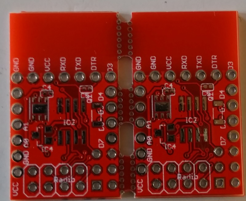
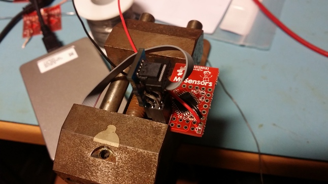
A couple of days ago I promised pictures of the new boards. Unfortunately I have been busy with some other projects :s (I hate it, when work related projects take too much of the spare time..).
Anyway, here are a couple of pictures, not the best quality, as it was a couple of quick snaps I took when I received the boards last week..
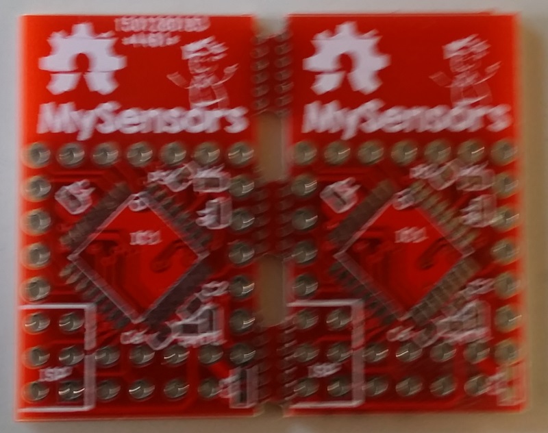
The front one is a bit blurry, sorry about that, but that is what I have at the moment..
@bjornhallberg as you can see it seems that it works quite well with adding the break tabs
@tbowmo Looks great! I hope my regulators turn out as nice. They should hopefully arrive next week.
Best thing about the panelizer is obviously if you mass produce different sized boards, and use 10x10 cm PCBs (that are almost half the price / square cm), not only fitting a ton of boards in one space, but beating the freeware limitation in Eagle.
-
So almost finished the first two boards of the new revision..
I changed the footprint of all the SMD capacitors, and resistors, to footprints recomended by the manufacturer we are in dialog with for the mass production. Only problem is, that it's a nightmare soldering the 0402 smd components now, because the footprints are much smaller than what was used on the first revision.
Anyway, only missing decoupling capacitors now, so I'm going to power it up, just to see if everything works like it should.
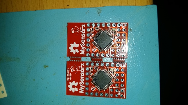
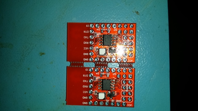
The two first is also with atsha204 mounted! Hope that everything is connected as it should be :)
First powerup seems to be ok. no excessive power ussage, and bootloader is successfully dumped into the first board. So it seems like a success sofar. (Even LED lights up during bootloader startup.. So that's also a success :))
Also ATSHA204 is confirmed working on the first prototype!
-
Properly done!
-
so @tbowmo when can we order em ? just waiting to get a may be around 10 to start with :)
-
To my best knowledge at the moment, it will be Q2 this year.
It should work, as the extra components added in rev. 2, have been verified as working (it's the atsha204 chip, for signing purposes). Everything else should be working, as I haven't altered in the schematics, so connections should be the same as the previous version.
@tbowmo Looking at the placement, I have a few questions regarding connectivity. With the RF-board mounted (looks like it goes in on the bottom layer), will it be possible to access the other holes?
Essentially, I wonder about the mounting possibilities. As there are no holes for screws, I am guessing the board is intended to be mated to a backplane using the IO-pins as interconnects? But will that be possible when the RF board is mounted? The programmer and FTDI-headers I suppose go up from the top layer so they are out of the way, but my concern is that the RF board will cover the IO-rows on the other side.
Or is the intention to have a board that is wire-soldered directly and RF module is mounted last? I worry a bit on maintenance then :) -
main thought was that it was only going to be used with wires connected to the board (that's the way I wanted to use it). the FTDI header, was only intended for downloading software, and debug purposes.
The radio will cover the FTDI header, and the pinheader on one of the sides of the board. So you have to mount the board to another board "upside down", that is with the atmega facing down to the other board. In this case the micro sensor is sandwitched between the radio module, and the extension board.
There are tradeoffs when trying to make things as small as possible (which was my initial goal of this board).
-
main thought was that it was only going to be used with wires connected to the board (that's the way I wanted to use it). the FTDI header, was only intended for downloading software, and debug purposes.
The radio will cover the FTDI header, and the pinheader on one of the sides of the board. So you have to mount the board to another board "upside down", that is with the atmega facing down to the other board. In this case the micro sensor is sandwitched between the radio module, and the extension board.
There are tradeoffs when trying to make things as small as possible (which was my initial goal of this board).
@tbowmo Sure, no problems. I was just wondering about the intended usecase. I think it should be possible to mount both the programming and the FTDI header on the same side though. This leaves the RF board free to use all needed space. And direct wires to all other IO. A "ugly" approach is also to simply not solder FTDI at all. Just put the pin header in and press it against the side when programming (if bootloader exists). Same could be done for the programming header (if you want a really thin board topology).
But since batteries will create some "height" I think it should be possible to keep both headers pointing up from the AVR-side of the board. Might I suggest for future revisions a 3mm mounting hole/point up center between the nice silk screen grafitti? But perhaps it will be obscured by the RF board. It will be tricky to get the board mounted through that hole in that case if it has to be done before the board is soldered I guess. Oh well, you can't get everything :)
Good work on the routing. The I2C pullups must have been painful.Do you feel secure today? No? Start requiring some signatures and feel better tomorrow ;)
-
@tbowmo Sure, no problems. I was just wondering about the intended usecase. I think it should be possible to mount both the programming and the FTDI header on the same side though. This leaves the RF board free to use all needed space. And direct wires to all other IO. A "ugly" approach is also to simply not solder FTDI at all. Just put the pin header in and press it against the side when programming (if bootloader exists). Same could be done for the programming header (if you want a really thin board topology).
But since batteries will create some "height" I think it should be possible to keep both headers pointing up from the AVR-side of the board. Might I suggest for future revisions a 3mm mounting hole/point up center between the nice silk screen grafitti? But perhaps it will be obscured by the RF board. It will be tricky to get the board mounted through that hole in that case if it has to be done before the board is soldered I guess. Oh well, you can't get everything :)
Good work on the routing. The I2C pullups must have been painful.@Anticimex said:
Just put the pin header in and press it against the side when programming
This is what I do with the Pro Mini, have not had any problems yet.
-
@tbowmo what might be the cost we are talking of here for the complete assembled board ?
-
I don't solder any pinheaders for the serial port, just putting the pins from the ftdi module in the holes on the micro board, and then holding it in place. Done the same thing for the ISP port, but it's a bit more problematic. The last two boards that I have assembled, is with pins in the ISP port.
I expect to have a "standard" bootloader in the boards (Together with a standard sketch for reading / reporting sensor values), when we receive them from China, so the ISP port is not necessary for the average user. only serial port for reprogramming (if not going for OTA).
But it might be an option for a future module, to have better access to the headers. Also might go with the nrf24 smd modules. But that's another project at the moment :)
@tbowmo Sure. But after a chat with @hek I believe you have dabbled with a bootloader that can flash in new FW from the external SPI flash. This is to me very interesting because that means we can deploy FW updates OTA using the MySensor library to flash the external flash, write some EEPROM byte to inform bootloader that new firmware is available, reboot to have the FW transferred by the bootloader and then boot the new FW. And this in turn means that we can transfer the new firmware signed, therefore support signed FOTA and THAT is very much interesting to me :)
So for me, the ideal would be that the board was preflashed with that bootloader (patched to be triggered by MySensors logic if necessary). Then there would be no requirement to have any extra headers, as you can push whatever you want, and signing can be implemented without actually changing the bootloader (headers will probably be needed during development, but that could just as well be done on breadboard).Do you feel secure today? No? Start requiring some signatures and feel better tomorrow ;)
-
@tbowmo Sure. But after a chat with @hek I believe you have dabbled with a bootloader that can flash in new FW from the external SPI flash. This is to me very interesting because that means we can deploy FW updates OTA using the MySensor library to flash the external flash, write some EEPROM byte to inform bootloader that new firmware is available, reboot to have the FW transferred by the bootloader and then boot the new FW. And this in turn means that we can transfer the new firmware signed, therefore support signed FOTA and THAT is very much interesting to me :)
So for me, the ideal would be that the board was preflashed with that bootloader (patched to be triggered by MySensors logic if necessary). Then there would be no requirement to have any extra headers, as you can push whatever you want, and signing can be implemented without actually changing the bootloader (headers will probably be needed during development, but that could just as well be done on breadboard). -
But you would still need to set the keys...
@hek Well, not really. If you like, you can FOTA down the personalizer with your PSK and execute it by remote on a "virgin" unit Then FOTA down your application FW. It is only when your application tells the GW that it require signing, signing actually kicks in.
-
Yes, I have a bootloader, that copies external flash, to internal. It's also verified as working, with a local firmware update where I downloaded a sketch to the micro, which put another sketch into the external flash, so no OTA in the verification phase. I used DualOptiboot from lowpowerlabs (There is a copy on my github account.)
The bootloader looks for a signature in the first couple of bytes of the external flash, if present it copies data and erases the external flash.
I just don't know what direction things are going at the moment, as there also exists the standard MySensors bootloader. If we use dualoptiboot, we need to have FOTA code in the default application that is loaded into the device, before shipment from china.
-
@tbowmo
Yes, that would be the most reliable option to allow updates un normal running mode.I discussed this with @Anticimex earlier today and how to combine it with signing without totally flood the network with nonce requests etc.
Neither of us have the flash memory though ;)
-
if we are going to use the external flash for OTA, then it should be included in the library? So the libraray handles the OTA packets, putting data into the external flash etc.
@tbowmo Yep. The way I understand how things work, I suggest the following:
Library initiates OTA transfer stream and transmit all FW for storage in external flash. Both sender and transmitter calculates some checksum of the FW and the checksum is sent finally, as a separate command.
The stream data is sent with a special command that bypasses signature. The checksum is sent with a type that is included with other signed types (currently only the singing handshake commands are excluded from signing).
That way, if receiver require it, FOTA will also be signed since the checksum packet is signed.
If the receiver accepts the signature (and the checksum is valid) receiver writes the bootloader specific indicators and restarts, so bootloader can transfer the received firmware to PROGMEM, and "Bob's your uncle". Secure FOTA to your difficult-to-reach node somewhere in the house :)