Minimal design thoughts
-
I have checked, and double checked fuses :) I'm using avrdude to program the bootloader directly, and it seems that it is starting up (the LED is lighting up as it is supposed to). Also when I program a sketch via ISP (using jtagice3) serial is working fine, so it seems that fuse settings is right for oscillator (at least)
But I might have missed something with the fuse settings.
I get these fuses
AVRDUDE -U lfuse:w:0xE2:m -U hfuse:w:0xDA:m -U efuse:w:0xFE:m -U lock:w:0xFF:mfrom http://eleccelerator.com/fusecalc/fusecalc.php?chip=atmega328p&LOW=E2&HIGH=DA&EXTENDED=FE&LOCKBIT=FF
@tbowmo I am just taking wild guesses and the one thing that came to my mind if you seem to have bootloader running but cannot download is that the serial line is out of sync for some reason. But I have not dissected the arduino bootloader or the protocol so I am in deep murky waters making assumptions now :)
-
Yeah, but it's hard to debug things in the bootloader.
-
I have checked, and double checked fuses :) I'm using avrdude to program the bootloader directly, and it seems that it is starting up (the LED is lighting up as it is supposed to). Also when I program a sketch via ISP (using jtagice3) serial is working fine, so it seems that fuse settings is right for oscillator (at least)
But I might have missed something with the fuse settings.
I get these fuses
AVRDUDE -U lfuse:w:0xE2:m -U hfuse:w:0xDA:m -U efuse:w:0xFE:m -U lock:w:0xFF:mfrom http://eleccelerator.com/fusecalc/fusecalc.php?chip=atmega328p&LOW=E2&HIGH=DA&EXTENDED=FE&LOCKBIT=FF
The fuse settings say 8Mhz internal, 2kb bootloader. Which bootloader are you using and did you adjust the baud settings in the boards.txt for the IDE (i.e. upload.speed=57600)? Also, do you get serial output at the set baud rate when uploading a simple serial output sketch via isp? Alternatively, I recommend recompiling the bootloader at 8Mhz for correct baud settings.
-
A case already was on my short-list and we could very well provide it.
Depending on demand it could be 3d-printed or for larger quantities done with mold injection by our partner.
But I would really need some help from a (talented) 3d modeller for this. Do we have anyone here that can help out?
The box must have a battery compartment for 2XAA. A big question is if it also should have space for an extra sensor?
Would be great if we could provide a couple of cover-options for things like motion (HC-SR501) and another for light/uv/ir sensor. Hope we can get creative together here.@hek Hello, I have a friend who is working with 3D modeling. i can study it. I do not guaranty for the moment, as it doesn't rely on me directly. however I can do the best, and try to move forward.
If I understand correctly, we need the place for the sensor+antenna+AA battery...
On the PCB, is there some hole to place some screws ?
How should we close the case ? by putting some screw or just putting a cover ? make sense ? -
@hek Hello, I have a friend who is working with 3D modeling. i can study it. I do not guaranty for the moment, as it doesn't rely on me directly. however I can do the best, and try to move forward.
If I understand correctly, we need the place for the sensor+antenna+AA battery...
On the PCB, is there some hole to place some screws ?
How should we close the case ? by putting some screw or just putting a cover ? make sense ?The board has humidity/temperature build in. So we only need space for maybe one extra sensor (question is how large volume this would need?).
Punch out holes for wires to external things like permanent power, buttons or reed-switches.Click on cover would be nice but requires more accuracy in the making. A screw wouldn't be a big problem.
Many variables... ;)
-
The board has humidity/temperature build in. So we only need space for maybe one extra sensor (question is how large volume this would need?).
Punch out holes for wires to external things like permanent power, buttons or reed-switches.Click on cover would be nice but requires more accuracy in the making. A screw wouldn't be a big problem.
Many variables... ;)
@hek I know , yes for the T/H sensor. As we put 2 AA battery, we have to know if we want to stack sensor/battery or not...otherwise, battery and sensor will be on the same plan.
I think that we can start without extra sensor, and add it in function of request, I'm going to buy a 3D printer, It will be my first tests. -
-
Why do not use CR123A accumulator?
It is smaller and can be charged.
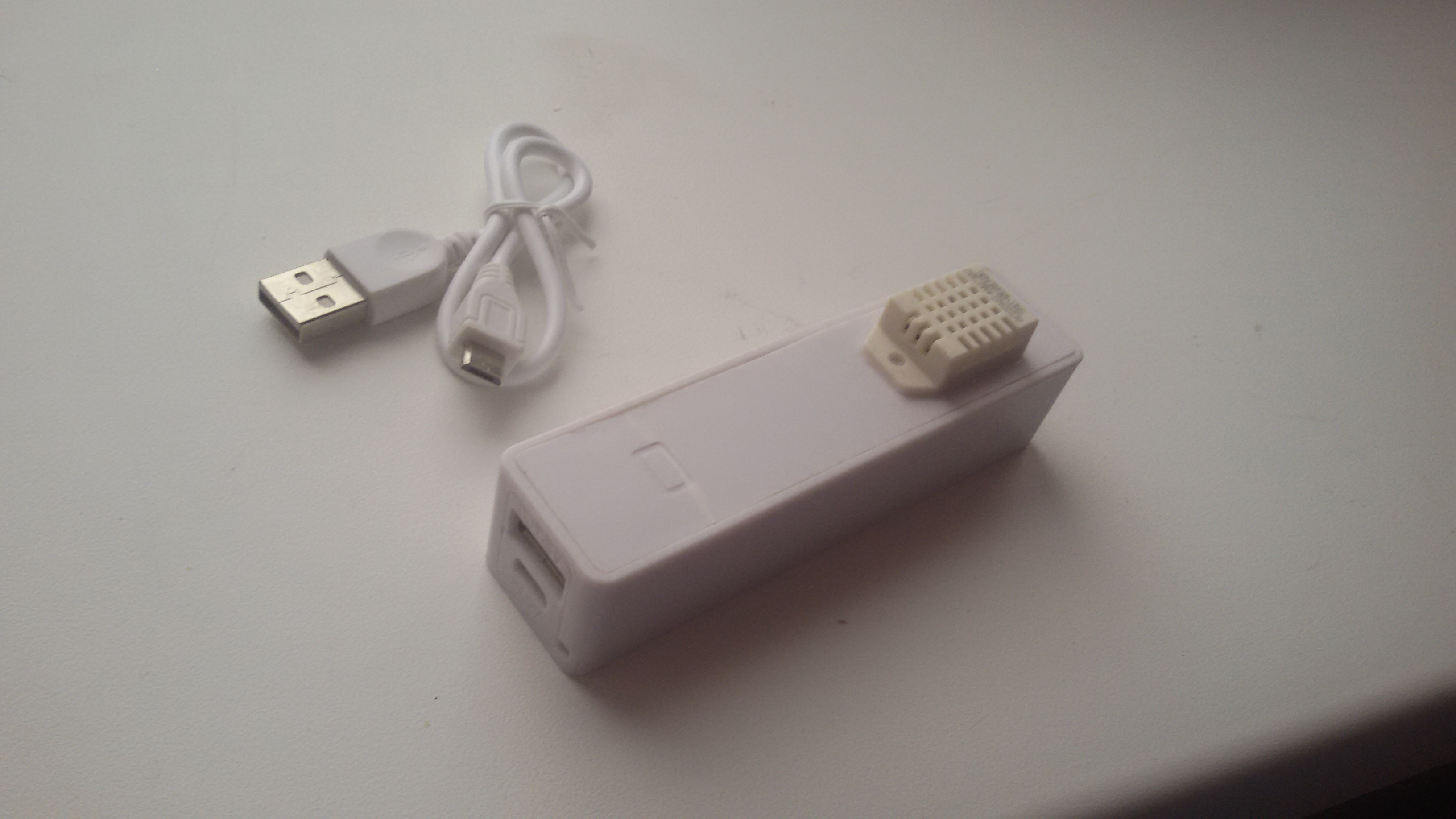
And not nide regulatorI use box with charger. With CR123A accumulator.
http://www.ebay.com/itm/2600Mah-USB-Portable-External-Battery-Charger-Power-Bank-for-Cell-Mobile-Phone-/301514424642?pt=LH_DefaultDomain_0&var=&hash=item4633a90142Very cheap
-
Why do not use CR123A accumulator?
It is smaller and can be charged.
And not nide regulatorI use box with charger. With CR123A accumulator.
http://www.ebay.com/itm/2600Mah-USB-Portable-External-Battery-Charger-Power-Bank-for-Cell-Mobile-Phone-/301514424642?pt=LH_DefaultDomain_0&var=&hash=item4633a90142Very cheap
-
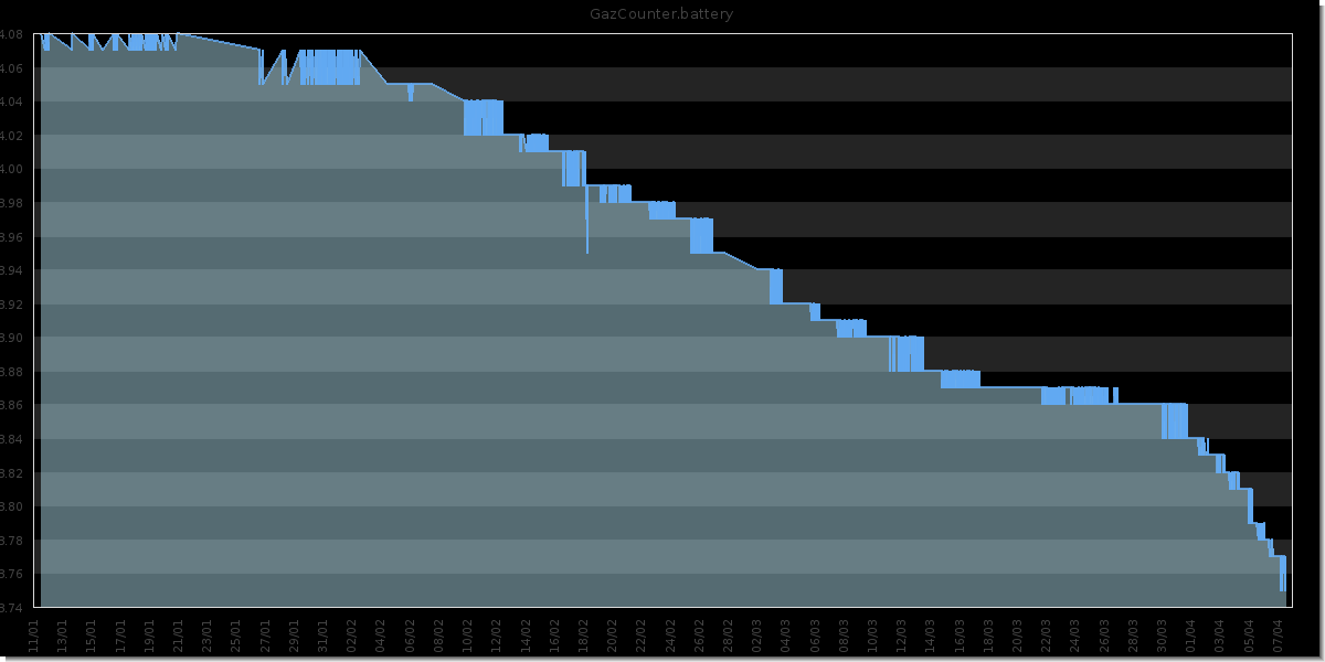
CR123A in full charge has 4.07v
Gas counter started 2014/11/01.
In winter, temperatures drop below -10
-
You say that it don't need a regulator? the battery voltage is 4.07 when fully charged, that is 0.47V above the absolute maximum rating of the NRF24L01+, as it's only rated to 3.6V maximum. Same goes for the Si7021, maximum supply voltage is 3.6V.
So CR123A is not a good battery, unless you put a regulator in the loop, which then again uses current, and causes a voltage drop from battery supply
-
DHT22 = 3.3-6V DC
CR123A = 3.6v ( Bat full charge i have 4.07v )
NRF24L01+ = 3.6
I have 8 device and his work with CR123A for 6 months
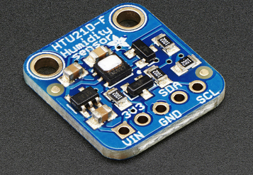
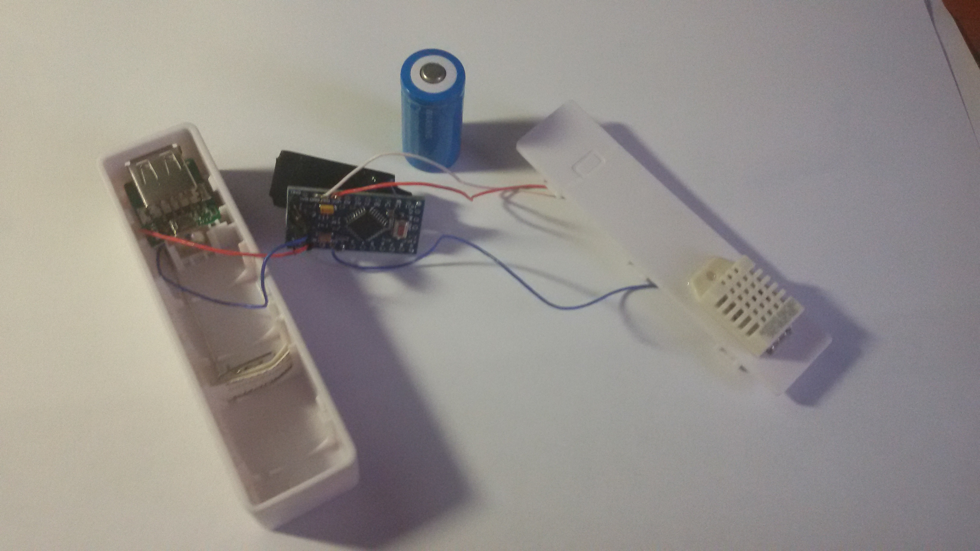
When charge some device cannot translate packets, but after work@Ivan-Z I think you are lucky... I burned a few radio's with a similar setup (with LiPO solar charger) I like your minimal design. If you replace the DHT sensor with a htu21 you can make it even smaller. There are a few htu21d boards with a 3.3v regulator on it which you could use to power the radio.
-
@AWI
What regulator do you use?I do not use the regulator because it has a extremeconsumption
AMS1117-3.3 = 5~10mV in idle@Ivan-Z I use the XC6206 series regulator. most of the times. The quiescent current for this one is very low 1-3 uA. This regulator is used by many of the sensor board suppliers to supply sensors with 3.3v Eg. In many cases (eg Adafruit) you can use the board as a "3.3v power supply"