[solved] RFM69 based nodes unable to report Lib Version
-
@korttoma
Here's my sketch. It's an MQTT GW with LEDs./** * The MySensors Arduino library handles the wireless radio link and protocol * between your home built sensors/actuators and HA controller of choice. * The sensors forms a self healing radio network with optional repeaters. Each * repeater and gateway builds a routing tables in EEPROM which keeps track of the * network topology allowing messages to be routed to nodes. * * Created by Henrik Ekblad <henrik.ekblad@mysensors.org> * Copyright (C) 2013-2015 Sensnology AB * Full contributor list: https://github.com/mysensors/Arduino/graphs/contributors * * Documentation: http://www.mysensors.org * Support Forum: http://forum.mysensors.org * * This program is free software; you can redistribute it and/or * modify it under the terms of the GNU General Public License * version 2 as published by the Free Software Foundation. * ******************************* * * REVISION HISTORY * Version 1.0 - Henrik Ekblad * * DESCRIPTION * The W5100 MQTT gateway sends radio network (or locally attached sensors) data to your MQTT broker. * The node also listens to MY_MQTT_TOPIC_PREFIX and sends out those messages to the radio network * * LED purposes: * - RX (yellow) - blink fast on radio message recieved. In inclusion mode will blink fast only on presentation received * - TX (green) - blink fast on radio message transmitted. In inclusion mode will blink slowly * - ERR (red) - fast blink on error during transmission error or receive crc error * */ // Enable debug prints to serial monitor #define MY_DEBUG // Enables and select radio type (if attached) //#define MY_RADIO_NRF24 #define MY_RADIO_RFM69 #define MY_RFM69_FREQUENCY RF69_433MHZ #define MY_GATEWAY_MQTT_CLIENT // Set this node's subscribe and publish topic prefix #define MY_MQTT_PUBLISH_TOPIC_PREFIX "my_RFM69_gw1-out" #define MY_MQTT_SUBSCRIBE_TOPIC_PREFIX "my_RFM69_gw1-in" // Set MQTT client id #define MY_MQTT_CLIENT_ID "mysensors_RFM69-1" // W5100 Ethernet module SPI enable (optional if using a shield/module that manages SPI_EN signal) //#define MY_W5100_SPI_EN 4 // Enable these if your MQTT broker requires username/password //#define MY_MQTT_USER "username" //#define MY_MQTT_PASSWORD "password" // Enable MY_IP_ADDRESS here if you want a static ip address (no DHCP) #define MY_IP_ADDRESS 192,168,1,93 // If using static ip you need to define Gateway and Subnet address as well #define MY_IP_GATEWAY_ADDRESS 192,168,1,1 #define MY_IP_SUBNET_ADDRESS 255,255,255,0 // MQTT broker ip address or url. Define one or the other. //#define MY_CONTROLLER_URL_ADDRESS "m20.cloudmqtt.com" #define MY_CONTROLLER_IP_ADDRESS 192, 168, 1, 90 // The MQTT broker port to to open #define MY_PORT 1883 // Set blinking period #define MY_DEFAULT_LED_BLINK_PERIOD 50 // Flash leds on rx/tx/err // Uncomment to override default HW configurations #define MY_DEFAULT_ERR_LED_PIN A3 // Error led pin #define MY_DEFAULT_RX_LED_PIN A2 // Receive led pin #define MY_DEFAULT_TX_LED_PIN A0 // Transmit led pin #include <Ethernet.h> // modified for W5500 module and with CS pin = D7 (Default CS pin D10 is already used by RFM69W module) #include <MySensors.h> void setup() { } void presentation() { // Present locally attached sensors here } void loop() { // Send locally attached sensors data here }@jpaulin Thanks, not much different from my sketch I see:
// Enable debug prints to serial monitor
#define MY_DEBUG

// Enable and select radio type attached
#define MY_RADIO_RFM69
#define MY_RFM69_FREQUENCY RF69_433MHZ
#define MY_RF69_SPI_CS 9
// Enable gateway ethernet module type
#define MY_GATEWAY_W5100


#define MY_IP_ADDRESS 192,168,1,25   // If this is disabled, DHCP is used to retrieve address

// The port to keep open on node server mode / or port to contact in client mode
#define MY_PORT 5003

// The MAC address can be anything you want but should be unique on your network.
// Newer boards have a MAC address printed on the underside of the PCB, which you can (optionally) use.
// Note that most of the Ardunio examples use  "DEAD BEEF FEED" for the MAC address.
#define MY_MAC_ADDRESS 0xDE, 0xAD, 0xBE, 0xEF, 0xFE, 0xED

// Flash leds on rx/tx/err
//#define MY_LEDS_BLINKING_FEATURE
// Set blinking period
#define MY_DEFAULT_LED_BLINK_PERIOD 300

// Enable inclusion mode
#define MY_INCLUSION_MODE_FEATURE
// Enable Inclusion mode button on gateway
//#define MY_INCLUSION_BUTTON_FEATURE
// Set inclusion mode duration (in seconds)
#define MY_INCLUSION_MODE_DURATION 60
// Digital pin used for inclusion mode button
#define MY_INCLUSION_MODE_BUTTON_PIN  3

// Uncomment to override default HW configurations
//#define MY_DEFAULT_ERR_LED_PIN 7  // Error led pin
//#define MY_DEFAULT_RX_LED_PIN  8  // Receive led pin
//#define MY_DEFAULT_TX_LED_PIN  9  // the PCB, on board LED

#include <SPI.h>

#if defined(MY_USE_UDP)
  #include <EthernetUdp.h>
#endif
#include <Ethernet.h>
#include <MySensors.h>


void setup(){
}

void loop() {
}
It has been running for a few hours now without issues. Gona try adding the buttons and relays tomorrow.
-
Adding the relays and buttons seems to work fine also. I will go with this setup now until there is a "Official" solution for the GatewayW5100RFM69.
/** * The MySensors Arduino library handles the wireless radio link and protocol * between your home built sensors/actuators and HA controller of choice. * The sensors forms a self healing radio network with optional repeaters. Each * repeater and gateway builds a routing tables in EEPROM which keeps track of the * network topology allowing messages to be routed to nodes. * * Created by Henrik Ekblad <henrik.ekblad@mysensors.org> * Copyright (C) 2013-2015 Sensnology AB * Full contributor list: https://github.com/mysensors/Arduino/graphs/contributors * * Documentation: http://www.mysensors.org * Support Forum: http://forum.mysensors.org * * This program is free software; you can redistribute it and/or * modify it under the terms of the GNU General Public License * version 2 as published by the Free Software Foundation. * ******************************* * * REVISION HISTORY * Version 1.0 - Henrik EKblad * Contribution by a-lurker and Anticimex, * Contribution by Norbert Truchsess <norbert.truchsess@t-online.de> * Contribution by Tomas Hozza <thozza@gmail.com> * * * DESCRIPTION * The EthernetGateway sends data received from sensors to the ethernet link. * The gateway also accepts input on ethernet interface, which is then sent out to the radio network. * * The GW code is designed for Arduino 328p / 16MHz. ATmega168 does not have enough memory to run this program. * * LED purposes: * - To use the feature, uncomment WITH_LEDS_BLINKING in MyConfig.h * - RX (green) - blink fast on radio message recieved. In inclusion mode will blink fast only on presentation recieved * - TX (yellow) - blink fast on radio message transmitted. In inclusion mode will blink slowly * - ERR (red) - fast blink on error during transmission error or recieve crc error * * See http://www.mysensors.org/build/ethernet_gateway for wiring instructions. * */ // Enable debug prints to serial monitor #define MY_DEBUG #define SN "EthGW/RFM69 Rele Button" #define SV "1.0" // Enable and select radio type attached //#define MY_RADIO_NRF24 #define MY_RADIO_RFM69 #define MY_RFM69_FREQUENCY RF69_433MHZ #define MY_RF69_SPI_CS 9 // Enable gateway ethernet module type #define MY_GATEWAY_W5100 // W5100 Ethernet module SPI enable (optional if using a shield/module that manages SPI_EN signal) //#define MY_W5100_SPI_EN 10 // Enable Soft SPI for NRF radio (note different radio wiring is required) // The W5100 ethernet module seems to have a hard time co-operate with // radio on the same spi bus. // Enable to UDP //#define MY_USE_UDP #define MY_IP_ADDRESS 192,168,1,25 // If this is disabled, DHCP is used to retrieve address // Renewal period if using DHCP //#define MY_IP_RENEWAL_INTERVAL 60000 // The port to keep open on node server mode / or port to contact in client mode #define MY_PORT 5003 // Controller ip address. Enables client mode (default is "server" mode). // Also enable this if MY_USE_UDP is used and you want sensor data sent somewhere. //#define MY_CONTROLLER_IP_ADDRESS 192, 168, 178, 254 // The MAC address can be anything you want but should be unique on your network. // Newer boards have a MAC address printed on the underside of the PCB, which you can (optionally) use. // Note that most of the Ardunio examples use "DEAD BEEF FEED" for the MAC address. #define MY_MAC_ADDRESS 0xDE, 0xAD, 0xBE, 0xEF, 0xFE, 0xED // Flash leds on rx/tx/err //#define MY_LEDS_BLINKING_FEATURE // Set blinking period #define MY_DEFAULT_LED_BLINK_PERIOD 300 // Enable inclusion mode #define MY_INCLUSION_MODE_FEATURE // Enable Inclusion mode button on gateway //#define MY_INCLUSION_BUTTON_FEATURE // Set inclusion mode duration (in seconds) #define MY_INCLUSION_MODE_DURATION 60 // Digital pin used for inclusion mode button #define MY_INCLUSION_MODE_BUTTON_PIN 3 // Uncomment to override default HW configurations //#define MY_DEFAULT_ERR_LED_PIN 7 // Error led pin //#define MY_DEFAULT_RX_LED_PIN 8 // Receive led pin //#define MY_DEFAULT_TX_LED_PIN 9 // the PCB, on board LED #include <SPI.h> #if defined(MY_USE_UDP) #include <EthernetUdp.h> #endif #include <Ethernet.h> #include <MySensors.h> #include <Bounce2.h> #define RELAY_ON 0 // switch around for ACTIVE LOW / ACTIVE HIGH relay #define RELAY_OFF 1 // #define noRelays 4 //2-4 const int relayPin[] = {14, 15, 16, 17}; // switch around pins to your desire const int buttonPin[] = {6, 7, 4, 5}; // switch around pins to your desire class Relay // relay class, store all relevant data (equivalent to struct) { public: int buttonPin; // physical pin number of button int relayPin; // physical pin number of relay boolean relayState; // relay status (also stored in EEPROM) }; Relay Relays[noRelays]; Bounce debouncer[noRelays]; MyMessage msg[noRelays]; void setup() { wait(100); // Initialize Relays with corresponding buttons for (int i = 0; i < noRelays; i++) { Relays[i].buttonPin = buttonPin[i]; // assign physical pins Relays[i].relayPin = relayPin[i]; msg[i].sensor = i; // initialize messages msg[i].type = V_LIGHT; pinMode(Relays[i].buttonPin, INPUT_PULLUP); wait(100); pinMode(Relays[i].relayPin, OUTPUT); Relays[i].relayState = loadState(i); // retrieve last values from EEPROM digitalWrite(Relays[i].relayPin, Relays[i].relayState ? RELAY_ON : RELAY_OFF); // and set relays accordingly send(msg[i].set(Relays[i].relayState ? true : false)); // make controller aware of last status wait(50); debouncer[i] = Bounce(); // initialize debouncer debouncer[i].attach(buttonPin[i]); debouncer[i].interval(30); wait(50); } } void presentation() { // Send the sketch version information to the gateway and Controller sendSketchInfo(SN, SV); wait(100); for (int i = 0; i < noRelays; i++) present(i, S_LIGHT); // present sensor to gateway wait(100); } void loop() { for (byte i = 0; i < noRelays; i++) { if (debouncer[i].update()) { int value = debouncer[i].read(); if ( value == LOW) { Relays[i].relayState = !Relays[i].relayState; digitalWrite(Relays[i].relayPin, Relays[i].relayState ? RELAY_ON : RELAY_OFF); send(msg[i].set(Relays[i].relayState ? true : false)); // save sensor state in EEPROM (location == sensor number) saveState( i, Relays[i].relayState ); } } } //wait(20); } void receive(const MyMessage &message) { if (message.type == V_LIGHT) { if (message.sensor < noRelays) { // check if message is valid for relays..... previous line [[[ if (message.sensor <=noRelays){ ]]] Relays[message.sensor].relayState = message.getBool(); digitalWrite(Relays[message.sensor].relayPin, Relays[message.sensor].relayState ? RELAY_ON : RELAY_OFF); // and set relays accordingly saveState( message.sensor, Relays[message.sensor].relayState ); // save sensor state in EEPROM (location == sensor number) } } wait(20); } -
@TimO
Hi.
Sorry for delay, so much projects.
As you tried to make a push, when you'll have some time, could you tell me if SOFTSPI is working please ? i'm a bit lazy to make a w5100 setup, as i'm not using it.https://github.com/scalz/Mysensors/tree/rfm69_update
Set of defines is
//#define MY_DEBUG
//#define MY_DEBUG_VERBOSE_RFM69
#define MY_RFM69_FREQUENCY   RFM69_868MHZ // RFM69_433MHZ for 433MHz, RFM69_868MHZ for default 868MHz or RF69_915MHZ for 915MHz
//#define MY_IS_RFM69HW // uncomment this if you're running the RFM69HW model

//#define MY_RFM69_TX_POWER_DBM (5) // default
//#define MY_RFM69_ATC_TARGET_RSSI_DBM	(-80) // default
//#define MY_RFM69_ATC_MODE_DISABLED
//#define MY_RFM69_NETWORKID     100  // default
//#define MY_RFM69_ENABLE_ENCRYPTION

//#define MY_RFM69_RST_PIN 9
//#define MY_RFM69_IRQ_PIN 5
//#define MY_RFM69_SPI_CS 23


// For Advanced users
//#define MY_RFM69_SPI_MAX_SPEED (4000000ul)
//#define MY_RFM69_BITRATE_MSB RFM69_BITRATEMSB_55555  // Bitrate is for users who knows what they're doing as it can impact your network reliabilty, and read the datasheet/registers.h file to get the right bitrate.
//#define MY_RFM69_BITRATE_LSB RFM69_BITRATELSB_55555  // So bitrates are hardwritten values

// Before radio sending, random delay, to be sure that two nodes which were waiting for free channel, doesn't send at same time and collide
// delay = MY_RFM69_CSMA_ADD_DELAY_BASE * random(1,MY_RFM69_CSMA_ADD_DELAY_COUNT)

//#define MY_RFM69_CSMA_ADD_DELAY_BASE 50  // default 50ms
//#define MY_RFM69_CSMA_ADD_DELAY_COUNT 10 // default max 10 counts
Note these are my defines for my ATSAM gw.
You can also send RSSI and powerlevel as internal msg by doing, like sendBattery function works.
Example:/* ====================================================================== Function: sendRadioStats Purpose : Sends radio rssi and powerlevel values Input : - force : Forces transmission of a value (even if it's the same as previous measurement) - ack : boolean. true if ack needed Output : - true if transmission occured Comments: ========================================================================= */ bool sendRadioStats(bool force, bool ack) { static int16_t lastRssi=0; int16_t rssiVal = transportGetRSSI(); uint8_t txPower = transportGetTxPower(); if (abs(lastRssi - rssiVal) >= 10 || force == true) { force = sendSignalStrength(rssiVal, ack); force |= sendTXPowerLevel(txPower, ack); lastRssi = rssiVal; } return force; } -
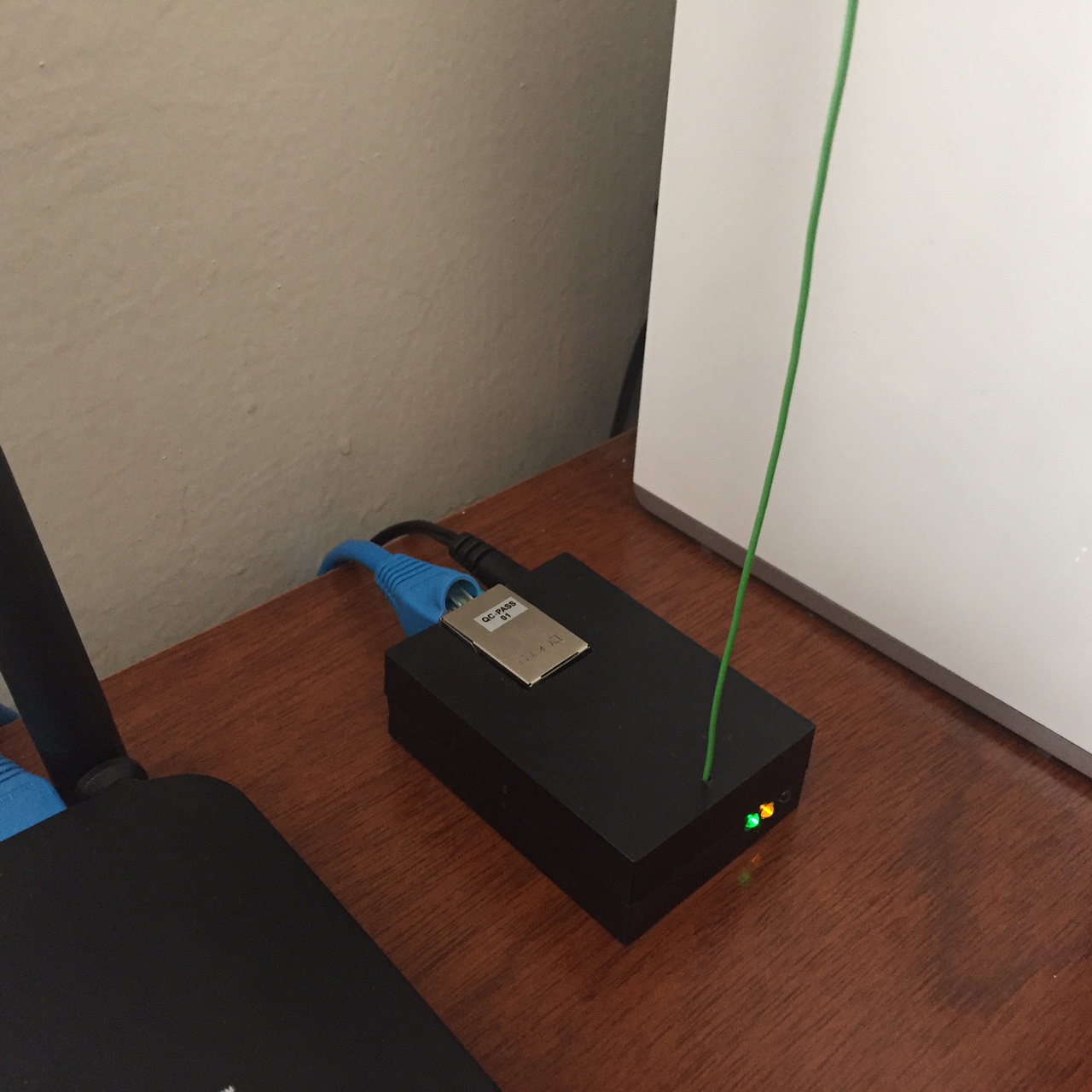
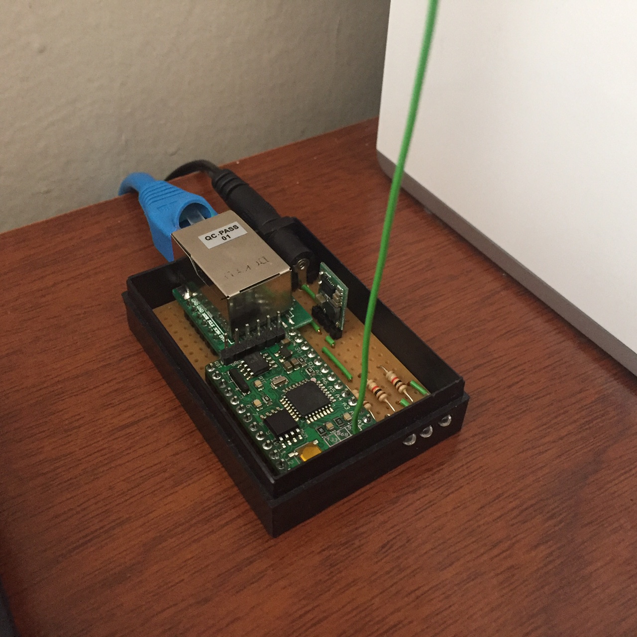
Okay, I found a little bit time to test and to check the wiring I've build a breadboard version.
Here's my sketch:
#define MY_DEBUG
#define MY_DEBUG_VERBOSE_RFM69

// Enable and select radio type attached
//#define MY_RADIO_NRF24
#define MY_RADIO_RFM69

#define MY_RFM69_FREQUENCY   RF69_868MHZ

// signing
//#define MY_SIGNING_SOFT
//#define MY_SIGNING_REQUEST_SIGNATURES

// Enable gateway ethernet module type
#define MY_GATEWAY_W5100

// W5100 Ethernet module SPI enable (optional if using a shield/module that manages SPI_EN signal)
//#define MY_W5100_SPI_EN 4

// Enable Soft SPI for NRF radio (note different radio wiring is required)
// The W5100 ethernet module seems to have a hard time co-operate with
// radio on the same spi bus.
#if !defined(MY_W5100_SPI_EN) && !defined(ARDUINO_ARCH_SAMD)
  #define MY_SOFTSPI
  #define MY_SOFT_SPI_SCK_PIN A0
  #define MY_SOFT_SPI_MISO_PIN A2
  #define MY_SOFT_SPI_MOSI_PIN A1
#endif

#define MY_RF69_SPI_CS 5
#define MY_RF69_IRQ_PIN 2

// Enable to UDP
//#define MY_USE_UDP

#define MY_IP_ADDRESS 192,168,2,222   // If this is disabled, DHCP is used to retrieve address
// Renewal period if using DHCP
//#define MY_IP_RENEWAL_INTERVAL 60000
// The port to keep open on node server mode / or port to contact in client mode
#define MY_PORT 5003

// Controller ip address. Enables client mode (default is "server" mode).
// Also enable this if MY_USE_UDP is used and you want sensor data sent somewhere.
//#define MY_CONTROLLER_IP_ADDRESS 192, 168, 178, 254

// The MAC address can be anything you want but should be unique on your network.
// Newer boards have a MAC address printed on the underside of the PCB, which you can (optionally) use.
// Note that most of the Ardunio examples use  "DEAD BEEF FEED" for the MAC address.
#define MY_MAC_ADDRESS 0xDF, 0xCD, 0xCD, 0xAF, 0xFE, 0xED


#if defined(MY_USE_UDP)
  #include <EthernetUdp.h>
#endif
#include <Ethernet.h>
#include <MySensors.h>


void setup()
{
}

void loop() {
}
Nothing that fancy. Some defines are using RFM69 while others use RF69 (IRQ, CS PIN).
The init is not working. I've inserted a serial print to see where it stops working. Here's the serial output:
0;255;3;0;9;MCO:BGN:INIT GW,CP=RRNGA--,VER=2.1.0-beta
0;255;3;0;9;TSM:INIT
0;255;3;0;9;TSF:WUR:MS=0
before
0;255;3;0;9;!TSM:INIT:TSP FAIL
0;255;3;0;9;TSM:FAIL:CNT=1
0;255;3;0;9;TSM:FAIL:PDT
0;255;3;0;9;TSM:FAIL:RE-INIT
0;255;3;0;9;TSM:INIT
It stops there. No more retries, nothing more.
Here's were the error seems to occure (line 116 of RFM69.cpp):
setHighPower(_isRFM69HW); // called regardless if it's a RFM69W or RFM69HW
	setMode(RF69_MODE_STANDBY);
	start = millis();
		Serial.println("before");
	while (((readReg(REG_IRQFLAGS1) & RF_IRQFLAGS1_MODEREADY) == 0x00) && millis()-start < timeout) {
		yield();
	} // wait for ModeReady
	if (millis()-start >= timeout) {
		return false;
	}
		Serial.println("after");

	attachInterrupt(_interruptNum, RFM69::isr0, RISING);

	selfPointer = this;
	_address = nodeID;
	return true;
The second debug output "after" is never reached.
If I disable RFM69 in the sketch and upload it, the ethernet part comes up just fine. The gateway is reachable per ping and telnet.
I've tested against my initial implementation: https://github.com/tobof/MySensors
The gateway comes up and is able to receive messages.
Here's the debug:0;255;3;0;9;MCO:BGN:INIT GW,CP=RRNGA--,VER=2.0.1-beta 0;255;3;0;9;TSM:INIT 0;255;3;0;9;TSM:INIT:TSP OK 0;255;3;0;9;TSM:INIT:GW MODE 0;255;3;0;9;TSM:READY IP: 192.168.2.222 0;255;3;0;9;MCO:REG:NOT NEEDED 0;255;3;0;9;MCO:BGN:STP 0;255;3;0;9;MCO:BGN:INIT OK,ID=0,PAR=0,DIS=0,REG=1 0;255;3;0;9;TSF:MSG:READ,111-111-255,s=255,c=3,t=7,pt=0,l=0,sg=0: 0;255;3;0;9;TSF:MSG:BC 0;255;3;0;9;TSF:MSG:FPAR REQ,ID=111 0;255;3;0;9;TSF:CKU:OK,FCTRL 0;255;3;0;9;TSF:MSG:GWL OK 0;255;3;0;9;TSF:MSG:SEND,0-0-111-111,s=255,c=3,t=8,pt=1,l=1,sg=0,ft=0,st=OK:0 0;255;3;0;9;TSF:MSG:READ,111-111-0,s=255,c=3,t=24,pt=1,l=1,sg=0:1 0;255;3;0;9;TSF:MSG:PINGED,ID=111,HP=1 0;255;3;0;9;TSF:MSG:SEND,0-0-111-111,s=255,c=3,t=25,pt=1,l=1,sg=0,ft=0,st=OK:1 0;255;3;0;9;TSF:MSG:READ,111-111-0,s=255,c=3,t=15,pt=6,l=2,sg=0:0101 0;255;3;0;9;TSF:MSG:SEND,0-0-111-111,s=255,c=3,t=15,pt=6,l=2,sg=0,ft=0,st=OK:0100 0;255;3;0;9;TSF:MSG:READ,111-111-0,s=255,c=0,t=18,pt=0,l=5,sg=0:2.0.0 0;255;3;0;9;TSF:MSG:READ,111-111-0,s=255,c=3,t=6,pt=1,l=1,sg=0:0 0;255;3;0;9;TSF:MSG:READ,111-111-0,s=255,c=3,t=11,pt=0,l=5,sg=0:Relay 0;255;3;0;9;TSF:MSG:READ,111-111-0,s=255,c=3,t=12,pt=0,l=3,sg=0:1.0 0;255;3;0;9;TSF:MSG:READ,111-111-0,s=1,c=0,t=3,pt=0,l=0,sg=0: 0;255;3;0;9;TSF:MSG:READ,111-111-0,s=2,c=0,t=3,pt=0,l=0,sg=0: 0;255;3;0;9;TSF:MSG:READ,111-111-0,s=3,c=0,t=3,pt=0,l=0,sg=0: 0;255;3;0;9;TSF:MSG:READ,111-111-0,s=4,c=0,t=3,pt=0,l=0,sg=0: 0;255;3;0;9;TSF:MSG:READ,111-111-0,s=5,c=0,t=3,pt=0,l=0,sg=0: 0;255;3;0;9;TSF:MSG:READ,111-111-0,s=6,c=0,t=3,pt=0,l=0,sg=0: 0;255;3;0;9;TSF:MSG:READ,111-111-0,s=7,c=0,t=3,pt=0,l=0,sg=0: 0;255;3;0;9;TSF:MSG:READ,111-111-0,s=8,c=0,t=3,pt=0,l=0,sg=0: 0;255;3;0;9;TSF:MSG:READ,111-111-0,s=255,c=3,t=26,pt=1,l=1,sg=0:2 0;255;3;0;9;TSF:MSG:SEND,0-0-111-111,s=255,c=3,t=27,pt=1,l=1,sg=0,ft=0,st=OK:1 0;255;3;0;9;TSF:MSG:READ,111-111-255,s=255,c=3,t=7,pt=0,l=0,sg=0: 0;255;3;0;9;TSF:MSG:BC 0;255;3;0;9;TSF:MSG:FPAR REQ,ID=111 0;255;3;0;9;TSF:PNG:SEND,TO=0 0;255;3;0;9;TSF:CKU:OK 0;255;3;0;9;TSF:MSG:GWL OK 0;255;3;0;9;TSF:MSG:SEND,0-0-111-111,s=255,c=3,t=8,pt=1,l=1,sg=0,ft=0,st=OK:0 0;255;3;0;9;TSF:MSG:READ,111-111-0,s=255,c=3,t=24,pt=1,l=1,sg=0:1 0;255;3;0;9;TSF:MSG:PINGED,ID=111,HP=1 0;255;3;0;9;TSF:MSG:SEND,0-0-111-111,s=255,c=3,t=25,pt=1,l=1,sg=0,ft=0,st=OK:1 0;255;3;0;9;TSF:MSG:READ,111-111-0,s=255,c=3,t=15,pt=6,l=2,sg=0:0101 0;255;3;0;9;TSF:MSG:SEND,0-0-111-111,s=255,c=3,t=15,pt=6,l=2,sg=0,ft=0,st=OK:0100 0;255;3;0;9;TSF:MSG:READ,111-111-0,s=255,c=0,t=18,pt=0,l=5,sg=0:2.0.0 0;255;3;0;9;TSF:MSG:READ,111-111-0,s=255,c=3,t=6,pt=1,l=1,sg=0:0 0;255;3;0;9;TSF:MSG:READ,111-111-0,s=255,c=3,t=11,pt=0,l=5,sg=0:Relay 0;255;3;0;9;TSF:MSG:READ,111-111-0,s=255,c=3,t=12,pt=0,l=3,sg=0:1.0 0;255;3;0;9;TSF:MSG:READ,111-111-0,s=1,c=0,t=3,pt=0,l=0,sg=0: 0;255;3;0;9;TSF:MSG:READ,111-111-0,s=2,c=0,t=3,pt=0,l=0,sg=0: 0;255;3;0;9;TSF:MSG:READ,111-111-0,s=3,c=0,t=3,pt=0,l=0,sg=0: 0;255;3;0;9;TSF:MSG:READ,111-111-0,s=4,c=0,t=3,pt=0,l=0,sg=0: 0;255;3;0;9;TSF:MSG:READ,111-111-0,s=5,c=0,t=3,pt=0,l=0,sg=0: 0;255;3;0;9;TSF:MSG:READ,111-111-0,s=6,c=0,t=3,pt=0,l=0,sg=0: 0;255;3;0;9;TSF:MSG:READ,111-111-0,s=7,c=0,t=3,pt=0,l=0,sg=0: 0;255;3;0;9;TSF:MSG:READ,111-111-0,s=8,c=0,t=3,pt=0,l=0,sg=0: 0;255;3;0;9;TSF:MSG:READ,111-111-0,s=255,c=3,t=26,pt=1,l=1,sg=0:2 0;255;3;0;9;TSF:MSG:SEND,0-0-111-111,s=255,c=3,t=27,pt=1,l=1,sg=0,ft=0,st=OK:1So I suppose the wiring is okay. I hope this helps!
-
@TimO
Your screenshots are based on the old driver ;)
You need to use "rfm69_update branch" on my repo. the whole repo. It's based on dev branch, few days ago, with the latest driver.https://github.com/scalz/Mysensors/tree/rfm69_update
Thx for your tests and feedbacks :)
-
@TimO
Your screenshots are based on the old driver ;)
You need to use "rfm69_update branch" on my repo. the whole repo. It's based on dev branch, few days ago, with the latest driver.https://github.com/scalz/Mysensors/tree/rfm69_update
Thx for your tests and feedbacks :)
@scalz dammit! :-(
Okay, so this time the compiler is throwing errors.
Here are the ones I ruled out:
diff --git a/drivers/RFM69/RFM69.cpp b/drivers/RFM69/RFM69.cpp
index 10d8369..f068ef1 100644
--- a/drivers/RFM69/RFM69.cpp
+++ b/drivers/RFM69/RFM69.cpp
@@ -79,16 +79,20 @@ LOCAL void RFM69_prepareSPITransaction(void)
 #endif

    // set RFM69 SPI settings
+   #if !defined(MY_SOFTSPI) && defined(SPI_HAS_TRANSACTION)
    _SPI.setDataMode(RFM69_SPI_DATA_MODE);
    _SPI.setBitOrder(RFM69_SPI_DATA_ORDER);
    _SPI.setClockDivider(RFM69_SPI_MAX_SPEED); // decided to slow down from DIV2 after SPI stalling in some instances, especially visible on mega1284p when RFM69 and FLASH chip both present
+   #endif
 #endif
 }

 LOCAL void RFM69_concludeSPITransaction(void)
 {
-#ifdef SPI_HAS_TRANSACTION
-   _SPI.endTransaction();
+#ifdef SPI_HAS_TRANSACTION
+   #if !defined(MY_SOFTSPI)
+      _SPI.endTransaction();
+   #endif
 #else
    // restore SPI settings to what they were before talking to RFM69
 #if defined (SPCR) && defined (SPSR)
@@ -199,7 +203,9 @@ LOCAL bool RFM69_initialise(const float frequency)
    // IRQ
    pinMode(RFM69_IRQ_DIO_PIN, INPUT);
 #if defined (SPI_HAS_TRANSACTION) && !defined (ESP8266)
-   _SPI.usingInterrupt(digitalPinToInterrupt(RFM69_IRQ_DIO_PIN));
+   #if !defined(MY_SOFTSPI)
+      _SPI.usingInterrupt(digitalPinToInterrupt(RFM69_IRQ_DIO_PIN));
+   #endif
 #endif

    attachInterrupt(digitalPinToInterrupt(RFM69_IRQ_DIO_PIN), RFM69_interruptHandler, RISING);
@@ -1120,4 +1126,4 @@ void readAllRegs(void)
 		}
 #endif
 	}
-}
\ No newline at end of file
+}
diff --git a/drivers/RFM69/RFM69.h b/drivers/RFM69/RFM69.h
index 433d6e1..8326f6e 100644
--- a/drivers/RFM69/RFM69.h
+++ b/drivers/RFM69/RFM69.h
@@ -78,11 +78,13 @@

 #define RFM69_SPI_CS		(SS)

+#define RFM69_SPI_DATA_MODE		SPI_MODE0		//!< SPI mode
+
 // SPI settings
 #if defined (ARDUINO) && !defined (__arm__) && !defined (_SPI)
 #include <SPI.h>
 #if defined(MY_SOFTSPI)
-SoftSPI<MY_SOFT_SPI_MISO_PIN, MY_SOFT_SPI_MOSI_PIN, MY_SOFT_SPI_SCK_PIN, MY_RFM69_SPI_DATA_MODE> _SPI;
+SoftSPI<MY_SOFT_SPI_MISO_PIN, MY_SOFT_SPI_MOSI_PIN, MY_SOFT_SPI_SCK_PIN, RFM69_SPI_DATA_MODE> _SPI;
 #else
 #define _SPI SPI
 #endif
@@ -100,7 +102,7 @@ extern HardwareSPI SPI;		//!< SPI


 #define RFM69_SPI_DATA_ORDER	MSBFIRST		//!< SPI data order
-#define RFM69_SPI_DATA_MODE		SPI_MODE0		//!< SPI mode
+
 #if !defined(MY_RFM69_SPI_MAX_SPEED)
 #define RFM69_SPI_MAX_SPEED		(2000000ul)	//!< SPI speed
 #else
@@ -524,4 +526,4 @@ void readAllRegs(void);

 #endif

-/** @}*/
\ No newline at end of file
+/** @}*/
(I only have time for a diff, sorry)
After the changes it gets stuck here:
In file included from /home/toberfoe/Arduino/libraries/MySensors/MySensors.h:306:0,
                 from /home/toberfoe/ownCloud/workspace/Testumgebung/Gateway-5100-RFM69/GatewayW5100/GatewayW5100.ino:100:
/home/toberfoe/Arduino/libraries/MySensors/core/MyTransportRFM69.cpp:25:1: error: 'RFM69' does not name a type
 RFM69 _radio(MY_RF69_SPI_CS, MY_RF69_IRQ_PIN, MY_RFM69HW, MY_RF69_IRQ_NUM);
 ^
/home/toberfoe/Arduino/libraries/MySensors/core/MyTransportRFM69.cpp: In function 'bool transportInit()':
/home/toberfoe/Arduino/libraries/MySensors/core/MyTransportRFM69.cpp:32:6: error: '_radio' was not declared in this scope
  if (_radio.initialize(MY_RFM69_FREQUENCY, _address, MY_RFM69_NETWORKID)) {
      ^
/home/toberfoe/Arduino/libraries/MySensors/core/MyTransportRFM69.cpp: In function 'void transportSetAddress(uint8_t)':
/home/toberfoe/Arduino/libraries/MySensors/core/MyTransportRFM69.cpp:47:2: error: '_radio' was not declared in this scope
  _radio.setAddress(address);
  ^
/home/toberfoe/Arduino/libraries/MySensors/core/MyTransportRFM69.cpp: In function 'bool transportSend(uint8_t, const void*, uint8_t)':
/home/toberfoe/Arduino/libraries/MySensors/core/MyTransportRFM69.cpp:57:9: error: '_radio' was not declared in this scope
  return _radio.sendWithRetry(to,data,len);
         ^
/home/toberfoe/Arduino/libraries/MySensors/core/MyTransportRFM69.cpp: In function 'bool transportAvailable()':
/home/toberfoe/Arduino/libraries/MySensors/core/MyTransportRFM69.cpp:62:9: error: '_radio' was not declared in this scope
  return _radio.receiveDone();
         ^
/home/toberfoe/Arduino/libraries/MySensors/core/MyTransportRFM69.cpp: In function 'uint8_t transportReceive(void*)':
/home/toberfoe/Arduino/libraries/MySensors/core/MyTransportRFM69.cpp:73:28: error: '_radio' was not declared in this scope
  memcpy(data,(const void *)_radio.DATA, _radio.DATALEN);
                            ^
/home/toberfoe/Arduino/libraries/MySensors/core/MyTransportRFM69.cpp: In function 'void transportPowerDown()':
/home/toberfoe/Arduino/libraries/MySensors/core/MyTransportRFM69.cpp:85:2: error: '_radio' was not declared in this scope
  _radio.sleep();
  ^
exit status 1
I have no time to investigate it further till saturday. :-/
-
this is because you have not completely updated your Mysensors folder.
The driver only is not enough because there are changes in others files like MyTransportRFM69.cpp, MyConfig etc.. -
this is because you have not completely updated your Mysensors folder.
The driver only is not enough because there are changes in others files like MyTransportRFM69.cpp, MyConfig etc.. -
@TimO
Oh my bad!
I didn't update MyTransportRFM69.cpp on my git (because i've two branch locally, and forgot about this one..). I've just pushed it. Downloaded my repo again, and it compiles fine now ;)sorry for waste of time, pff :blush:
Also, if someone wants to try using W5100 and RFM69 on the same SPI bus (so not in softspi mode). I'm interested to know if it's working. As W5100 and the new RFM69 are using SPI transactions, and in RFM69 it now uses the spi.usinginterrupts , so it might work.
Note: as it's hardwritten in w5100 lib (not cool!), easier for tests to use- D10 for your w5100 SPI CS
- what you want for your RFM69 SPI CS. example for D6, using #define MY_RFM69_SPI_CS 6
-
Okay, so next run. :D
I've pulled your repo and tested with the sketch above. The compile does not work for the GatewayW5100 example sketch either.
I have to apply the diff I've posted above to make it compile. With the diff applied the gateway starts, is pingable and reachable via telnet but does not receive any packets via RFM69.My guess: SoftSPI has no methods "usingInterrupt()", "beginTransaction()", and "endTransaction()" and that's the reason why no packets are received. In the current implementation these methods were not used.
I suppose there needs to be an implementation without transactions for SoftSPI?
Here's the output of the compile without the diff applied:
n file included from /home/toberfoe/Arduino/libraries/MySensors/drivers/RFM69/RFM69.cpp:36:0, from /home/toberfoe/Arduino/libraries/MySensors/MySensors.h:305, from /tmp/arduino_modified_sketch_920203/GatewayW5100.ino:116: /home/toberfoe/Arduino/libraries/MySensors/drivers/RFM69/RFM69.h:85:74: error: 'MY_RFM69_SPI_DATA_MODE' was not declared in this scope SoftSPI<MY_SOFT_SPI_MISO_PIN, MY_SOFT_SPI_MOSI_PIN, MY_SOFT_SPI_SCK_PIN, MY_RFM69_SPI_DATA_MODE> _SPI; ^ /home/toberfoe/Arduino/libraries/MySensors/drivers/RFM69/RFM69.h:85:96: error: template argument 4 is invalid SoftSPI<MY_SOFT_SPI_MISO_PIN, MY_SOFT_SPI_MOSI_PIN, MY_SOFT_SPI_SCK_PIN, MY_RFM69_SPI_DATA_MODE> _SPI; ^ /home/toberfoe/Arduino/libraries/MySensors/drivers/RFM69/RFM69.h:85:102: error: invalid type in declaration before ';' token SoftSPI<MY_SOFT_SPI_MISO_PIN, MY_SOFT_SPI_MOSI_PIN, MY_SOFT_SPI_SCK_PIN, MY_RFM69_SPI_DATA_MODE> _SPI; ^ In file included from /home/toberfoe/Arduino/libraries/MySensors/MySensors.h:305:0, from /tmp/arduino_modified_sketch_920203/GatewayW5100.ino:116: /home/toberfoe/Arduino/libraries/MySensors/drivers/RFM69/RFM69.cpp: In function 'void RFM69_prepareSPITransaction()': /home/toberfoe/Arduino/libraries/MySensors/drivers/RFM69/RFM69.cpp:82:9: error: request for member 'setDataMode' in '_SPI', which is of non-class type 'int' _SPI.setDataMode(RFM69_SPI_DATA_MODE); ^ /home/toberfoe/Arduino/libraries/MySensors/drivers/RFM69/RFM69.cpp:83:9: error: request for member 'setBitOrder' in '_SPI', which is of non-class type 'int' _SPI.setBitOrder(RFM69_SPI_DATA_ORDER); ^ /home/toberfoe/Arduino/libraries/MySensors/drivers/RFM69/RFM69.cpp:84:9: error: request for member 'setClockDivider' in '_SPI', which is of non-class type 'int' _SPI.setClockDivider(RFM69_SPI_MAX_SPEED); // decided to slow down from DIV2 after SPI stalling in some instances, especially visible on mega1284p when RFM69 and FLASH chip both present ^ In file included from /home/toberfoe/Arduino/libraries/MySensors/MySensors.h:305:0, from /tmp/arduino_modified_sketch_920203/GatewayW5100.ino:116: /home/toberfoe/Arduino/libraries/MySensors/drivers/RFM69/RFM69.cpp: In function 'void RFM69_concludeSPITransaction()': /home/toberfoe/Arduino/libraries/MySensors/drivers/RFM69/RFM69.cpp:91:9: error: request for member 'endTransaction' in '_SPI', which is of non-class type 'int' _SPI.endTransaction(); ^ /home/toberfoe/Arduino/libraries/MySensors/drivers/RFM69/RFM69.cpp: In function 'uint8_t RFM69_spiMultiByteTransfer(uint8_t, uint8_t*, uint8_t, bool)': /home/toberfoe/Arduino/libraries/MySensors/drivers/RFM69/RFM69.cpp:114:18: error: request for member 'transfer' in '_SPI', which is of non-class type 'int' status = _SPI.transfer(cmd); ^ /home/toberfoe/Arduino/libraries/MySensors/drivers/RFM69/RFM69.cpp:117:24: error: request for member 'transfer' in '_SPI', which is of non-class type 'int' status = _SPI.transfer((uint8_t)0x00); ^ /home/toberfoe/Arduino/libraries/MySensors/drivers/RFM69/RFM69.cpp:122:24: error: request for member 'transfer' in '_SPI', which is of non-class type 'int' status = _SPI.transfer(*current++); ^ /home/toberfoe/Arduino/libraries/MySensors/drivers/RFM69/RFM69.cpp: In function 'bool RFM69_initialise(float)': /home/toberfoe/Arduino/libraries/MySensors/drivers/RFM69/RFM69.cpp:190:9: error: request for member 'begin' in '_SPI', which is of non-class type 'int' _SPI.begin(); ^ /home/toberfoe/Arduino/libraries/MySensors/drivers/RFM69/RFM69.cpp:202:9: error: request for member 'usingInterrupt' in '_SPI', which is of non-class type 'int' _SPI.usingInterrupt(digitalPinToInterrupt(RFM69_IRQ_DIO_PIN)); ^ /home/toberfoe/Arduino/libraries/MySensors/drivers/RFM69/RFM69.cpp: In function 'void RFM69_interruptHandler()': /home/toberfoe/Arduino/libraries/MySensors/drivers/RFM69/RFM69.cpp:232:15: error: request for member 'transfer' in '_SPI', which is of non-class type 'int' _SPI.transfer(RFM69_REG_FIFO & RFM69_READ_REGISTER); ^ /home/toberfoe/Arduino/libraries/MySensors/drivers/RFM69/RFM69.cpp:239:31: error: request for member 'transfer' in '_SPI', which is of non-class type 'int' *current++ = _SPI.transfer((uint8_t)0x00); ^ exit status 1 Fehler beim Kompilieren für das Board Arduino Nano. -
@TimO
Oh my bad!
I didn't update MyTransportRFM69.cpp on my git (because i've two branch locally, and forgot about this one..). I've just pushed it. Downloaded my repo again, and it compiles fine now ;)sorry for waste of time, pff :blush:
Also, if someone wants to try using W5100 and RFM69 on the same SPI bus (so not in softspi mode). I'm interested to know if it's working. As W5100 and the new RFM69 are using SPI transactions, and in RFM69 it now uses the spi.usinginterrupts , so it might work.
Note: as it's hardwritten in w5100 lib (not cool!), easier for tests to use- D10 for your w5100 SPI CS
- what you want for your RFM69 SPI CS. example for D6, using #define MY_RFM69_SPI_CS 6
-
@TimO
Oh my bad!
I didn't update MyTransportRFM69.cpp on my git (because i've two branch locally, and forgot about this one..). I've just pushed it. Downloaded my repo again, and it compiles fine now ;)sorry for waste of time, pff :blush:
Also, if someone wants to try using W5100 and RFM69 on the same SPI bus (so not in softspi mode). I'm interested to know if it's working. As W5100 and the new RFM69 are using SPI transactions, and in RFM69 it now uses the spi.usinginterrupts , so it might work.
Note: as it's hardwritten in w5100 lib (not cool!), easier for tests to use- D10 for your w5100 SPI CS
- what you want for your RFM69 SPI CS. example for D6, using #define MY_RFM69_SPI_CS 6
@scalz I downloaded your testbed and loaded a node with a basic script. It compiles ok, but I can't reach my gateway any longer. Do I have to update the gw as well? I'm using an ATmega328 with an RFM69W, CS=D10 and IRQ=D2 (Anarduino).
Looks inspiring with ATC, debug_verbose, getRSSI() and other improvements.Script used:
// Enable debug prints
#define MY_DEBUG
#define MY_DEBUG_VERBOSE_RFM69

// Enable and select radio type attached
//#define MY_RADIO_NRF24
#define MY_RADIO_RFM69

#define MY_RFM69_FREQUENCY   RFM69_433MHZ  // Note. New format

#define MY_NODE_ID 7

#include <MySensors.h>

unsigned long SLEEP_TIME = 5000;         // Sleep time between reads (in milliseconds)

#define CHILD_ID 1
MyMessage msg(CHILD_ID, V_VAR1);
int count = 0;

void setup()
{
}

void presentation()
{
  // Send the sketch version information to the gateway and Controller
  sendSketchInfo("Test", "1.0");

  // Register all sensors to gw (they will be created as child devices)
  present(CHILD_ID, S_CUSTOM);
}

void loop()
{
    send(msg.set(count));
    count++;
    if (count > 1000) {
      count=0;
    }

  wait(SLEEP_TIME);                       //sleep a bit.
}
Debug dump:
0 MCO:BGN:INIT NODE,CP=RRNNA--,VER=2.1.0-beta 4 TSM:INIT 4 TSF:WUR:MS=0 6 RFM69:INIT 7 RFM69:IRQ PIN=2,CS PIN=10 10 RFM69:PTX:LEVEL=5 dBm,reg=23 13 TSM:INIT:TSP OK 15 TSM:INIT:STATID=7 16 TSF:SID:OK,ID=7 18 TSM:FPAR 19 RFM69:SWR:Sending,to=255,retry=0 275 TSF:MSG:SEND,7-7-255-255,s=255,c=3,t=7,pt=0,l=0,sg=0,ft=0,st=OK: 2282 !TSM:FPAR:NO REPLY 2284 TSM:FPAR 2285 RFM69:SWR:Sending,to=255,retry=0 2691 TSF:MSG:SEND,7-7-255-255,s=255,c=3,t=7,pt=0,l=0,sg=0,ft=0,st=OK: 4698 !TSM:FPAR:NO REPLY 4700 TSM:FPAR 4701 RFM69:SWR:Sending,to=255,retry=0 5007 TSF:MSG:SEND,7-7-255-255,s=255,c=3,t=7,pt=0,l=0,sg=0,ft=0,st=OK: 7014 !TSM:FPAR:NO REPLY 7016 TSM:FPAR 7017 RFM69:SWR:Sending,to=255,retry=0 7173 TSF:MSG:SEND,7-7-255-255,s=255,c=3,t=7,pt=0,l=0,sg=0,ft=0,st=OK: 9180 !TSM:FPAR:FAIL 9181 TSM:FAIL:CNT=1 9183 TSM:FAIL:PDT 9185 RFM69:power down -
this is because you have not completely updated your Mysensors folder.
The driver only is not enough because there are changes in others files like MyTransportRFM69.cpp, MyConfig etc..@scalz Made some other tests and I get the same result.
- Testbed loaded in node only. No contact between gw and node.
- Testbed loaded in node and gw. No contact between gw and node.
- Testbed loaded in gw only. No contact between gw and node.
- @tekka RFM69DriverUpdate testbed loaded in node only. No contact between node and gw.
- Restoring node and gw with development branch. Everything goes back to normal.
GW uses hardware SPI for the radio and Ethernet unit as mentioned further up in this thread.
-
@TimO
oki, i'm fixing this, about your compil issue. i'll push today.@korttoma
I know about this ;) this is a problem related to the ethernet lib with pins hardwritten..Changes in new drivers should be able to handle hardware spi for w5100+radio on same bus. If taking care about the CS issue in ethernet lib. I've quickly looked and it seems that ethernet lib uses spi transaction, and rfm69 too now. So it should be ok in theory (for more infos, see spitransaction, and usinginterrupts).
D10 is default for w5100 in ethernet lib, but if not setting any define in Mysensors for radio, then it will be on D10 too.
- So if keeping W5100 D10, then we should have #define MY_RFM69_SPI_CS [your pin]
- Or hack the w5100 lib, and you can keep default D10 CS Mysensors define for radio.
So talking about this @jpaulin , could you tell me what are your CS pins? In your sketch above i don't see any define for this. So i assume you have modified the ethernet lib and keep Mysensors define for this, right ?
@scalz
On the test node CS = D10 (script above). On the gw the radio CS = D10 and the Ethernet CS = D7. D7 is set in the w5100.h file in the Ethernet library.Here's a debug dump with the RFM69 registers (from the test node):
0 MCO:BGN:INIT NODE,CP=RRNNA--,VER=2.1.0-beta
4 TSM:INIT
4 TSF:WUR:MS=0
6 RFM69:INIT
7 RFM69:IRQ PIN=2,CS PIN=10
9 RFM69:write register, reg=0x01, value=4
13 RFM69:write register, reg=0x02, value=0
17 RFM69:write register, reg=0x03, value=2
21 RFM69:write register, reg=0x04, value=64
24 RFM69:write register, reg=0x05, value=3
28 RFM69:write register, reg=0x06, value=51
32 RFM69:write register, reg=0x07, value=108
36 RFM69:write register, reg=0x08, value=64
40 RFM69:write register, reg=0x09, value=0
45 RFM69:write register, reg=0x18, value=136
48 RFM69:write register, reg=0x19, value=66
52 RFM69:write register, reg=0x26, value=7
56 RFM69:write register, reg=0x28, value=16
60 RFM69:write register, reg=0x29, value=220
64 RFM69:write register, reg=0x2e, value=136
68 RFM69:write register, reg=0x2f, value=170
72 RFM69:write register, reg=0x30, value=100
76 RFM69:write register, reg=0x37, value=212
80 RFM69:write register, reg=0x38, value=66
83 RFM69:write register, reg=0x39, value=255
88 RFM69:write register, reg=0x3a, value=255
92 RFM69:write register, reg=0x3c, value=5
96 RFM69:write register, reg=0x3d, value=16
100 RFM69:write register, reg=0x6f, value=48
104 RFM69:write register, reg=0x01, value=4
108 RFM69:read register, reg=0x27, value=128
112 RFM69:read register, reg=0x3d, value=16
115 RFM69:write register, reg=0x3d, value=16
119 RFM69:write register, reg=0x11, value=151
123 RFM69:PTX:LEVEL=5 dBm,reg=23
126 RFM69:read register, reg=0x02, value=0
131 RFM69:read register, reg=0x03, value=2
135 RFM69:read register, reg=0x04, value=64
138 RFM69:read register, reg=0x05, value=3
142 RFM69:read register, reg=0x06, value=51
146 RFM69:read register, reg=0x07, value=108
150 RFM69:read register, reg=0x08, value=64
154 RFM69:read register, reg=0x09, value=0
157 RFM69:read register, reg=0x30, value=100
161 TSM:INIT:TSP OK
163 TSM:INIT:STATID=7
165 RFM69:write register, reg=0x39, value=7
169 TSF:SID:OK,ID=7
172 TSM:FPAR
173 RFM69:SWR:Sending,to=255,retry=0
427 RFM69:read register, reg=0x27, value=128
431 RFM69:write register, reg=0x25, value=0
434 RFM69:write register, reg=0x01, value=12
441 RFM69:read register, reg=0x28, value=8
441 RFM69:write register, reg=0x25, value=64
441 RFM69:read register, reg=0x28, value=8
441 RFM69:write register, reg=0x01, value=16
442 TSF:MSG:SEND,7-7-255-255,s=255,c=3,t=7,pt=0,l=0,sg=0,ft=0,st=OK:
2449 !TSM:FPAR:NO REPLY
2451 TSM:FPAR
2452 RFM69:SWR:Sending,to=255,retry=0
2455 RFM69:read register, reg=0x24, value=195
2859 RFM69:read register, reg=0x24, value=197
2863 RFM69:write register, reg=0x01, value=4
2866 RFM69:read register, reg=0x27, value=128
2871 RFM69:write register, reg=0x25, value=0
2874 RFM69:write register, reg=0x01, value=12
2881 RFM69:read register, reg=0x28, value=8
2881 RFM69:write register, reg=0x25, value=64
2881 RFM69:read register, reg=0x28, value=8
2881 RFM69:write register, reg=0x01, value=16
2882 TSF:MSG:SEND,7-7-255-255,s=255,c=3,t=7,pt=0,l=0,sg=0,ft=0,st=OK:
4889 !TSM:FPAR:NO REPLY
4891 TSM:FPAR
4892 RFM69:SWR:Sending,to=255,retry=0
4895 RFM69:read register, reg=0x24, value=189
5199 RFM69:read register, reg=0x24, value=208
5203 RFM69:write register, reg=0x01, value=4
5207 RFM69:read register, reg=0x27, value=128
5212 RFM69:write register, reg=0x25, value=0
5215 RFM69:write register, reg=0x01, value=12
5222 RFM69:read register, reg=0x28, value=8
5222 RFM69:write register, reg=0x25, value=64
5222 RFM69:read register, reg=0x28, value=8
5222 RFM69:write register, reg=0x01, value=16
5223 TSF:MSG:SEND,7-7-255-255,s=255,c=3,t=7,pt=0,l=0,sg=0,ft=0,st=OK:
7230 !TSM:FPAR:NO REPLY
7232 TSM:FPAR
7233 RFM69:SWR:Sending,to=255,retry=0
7236 RFM69:read register, reg=0x24, value=222
7390 RFM69:read register, reg=0x24, value=193
7394 RFM69:write register, reg=0x01, value=4
7397 RFM69:read register, reg=0x27, value=128
7402 RFM69:write register, reg=0x25, value=0
7405 RFM69:write register, reg=0x01, value=12
7412 RFM69:read register, reg=0x28, value=8
7412 RFM69:write register, reg=0x25, value=64
7412 RFM69:read register, reg=0x28, value=8
7412 RFM69:write register, reg=0x01, value=16
7413 TSF:MSG:SEND,7-7-255-255,s=255,c=3,t=7,pt=0,l=0,sg=0,ft=0,st=OK:
9420 !TSM:FPAR:FAIL
9421 TSM:FAIL:CNT=1
9423 TSM:FAIL:PDT
9425 RFM69:power down
9427 RFM69:write register, reg=0x01, value=128