Powering mote 24/7 using only a supercap and solar
-
@mfalkvidd said:
@NeverDie if you eant to compare different caps, see if you can remove the solar panel from the equation. I think the variability of the solar panel voltage will make comparison difficult.
Yeah, I'm not quite ready to try supercap charging from the solar cell just yet. However, I'm not worried about variability: in the room where I'm testing, the solar cell would be illuminated by just the ceiling light, which is very constant in brightness, and nothing else.
At least so far the Vishay 15F supercap (see above) is holding up much better than the others. Today, the second day of testing on it, it's losing only about 5 millivolts per 12 hour period.
-
I hooked up an ADS1220 24-bit ADC to the supercap so that I could see in near real-time whether the solar charger was charger was charging the supercap, or having little to no effect.
Bottom line: if the solar cell is in a room that is well lit, by either natural or artificial means, then the BQ25504 charge circuit will charge the supercap faster than ithe supercap self discharges. On the other hand, if the room is only dimly lit, then the BQ25504 charger does not seem to be charging the supercap in any meaningful way. So, if dim lighting is an important use case to consider, one might need a bigger solar cell of some kind.
-
I notice now that leaving the BQ25504 connected to the supercap at night when there's no light to harvest does result is a cumulative drain of about 50 millivolts to the 15F supercap (charged to 3.340 volts) versus disconnecting it during the same period.
-
I finished the LTC3501 energy harvester (https://www.openhardware.io/view/281/Solar-Energy-Harvester), but, disappointingly, its MPPC seems to be no match for the MPPT of the BQ25504 for the el cheapo solar cell.
I think the next step will be to modify the BQ25504 breakout board to include the supercap. Going forward that should keep everything neat and tidy and avoid loose wiring.
-
I've designed the load switch and the supercap onto the PCB, and I just now sent it off to the fab. The entire board is less than 0.9 square inches in size.
-
Another notion I'm toying with is a variation of the proverb "make hay while the sun is shining." In other words, squirrel away as much solar energy as possible when conditions are optimal, and not worry too much about extracting light under truly dim conditions. I think there's a happy medium to be found, and I hope that by playing around with it a bit I'll develop a better sense as to where that sweet spot is.
-
Here's the version that I most recently assembled:
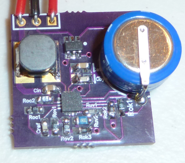
As you can see, the 15F supercap is now on the board itself. It works fine.I've since made a few refinements and have sent the new files off to be fabbed. The newest version of the PCB will measure roughly 22mm x 22mm.
-
I'm very curious to know what kind of sensor you would be able to run with this project. Of course a lot will depends on the size of solar panel and how much light it will get.
@gohan
Early tests indicate the 15F charges to 3.6v pretty fast on even ambient light. I realize that's a somewhat vague statement, but I hope to eventually quantify it better (charge time as a function of lux level, panel size, and nominal panel voltage). Nonetheless, based on early preliminary measurements, I'm pretty confident the answer is going to be fairly simple, namely: what can you do with 15F of charge?Before I began this project, I was quite worried that self discharge would strongly govern the answer, but this particular supercap (as contrasted to others I tested) seems to have a relatively low rate of self discharge. Early tests show the same also holds true for its bigger brother, the 90F supercap, in case the 15F isn't enough. The 15F supercap is rated for 100,000 charge/discharge cycles, so it won't be wearing out anytime soon if it's operated indoors under normal ambient temperature conditions. There are probably even more interesting supercaps out there, but for me this one's an existence proof and a fixed point I can gather data around.
If anyone knows of even better supercaps to try, I'm all ears.
-
Think of it like a battery whose voltage starts at 3.6v and then over time gradually drops to 1.8v. As presently configured, you would stop when the voltage gets to 1.8v, because both the atmega328p and the RFM69HW require a minimum 1.8v to operate.
-
Not sure the answer to that. However, one thing's worth noting: these supercaps behave more like button cells than capacitors. By that I mean: they can have voltage droops and can even have voltage "recovery" after using them a bit. I really didn't expect that going into this, but it's a very significant effect.
-
@gohan said in Powering mote 24/7 using only a supercap and solar:
What do you mean that they behave more like cells?
By that I mean: they can have voltage droops and can even have voltage "recovery" after using them a bit.
An "ideal" capacitor doesn't behave like that.
-
Sorry but I don't understand, I'm not that much into this electronic deep knowledge. By voltage drops are you referring to the small energy drain that the capacitor has?
-
Good news! Last night I did some accelerated load testing on the supercap. First I charged it to 3.6v and then I hooked up an RFM69HW mote which woke up once a second to do 3 things: 1. check the voltage level, 2. turn on an LED for 1ms to simulate a sensor load, and 3. transmit a packet containing the voltage data using the RFM69HW.. Bottom line: 14,111 packets transmitted before running out of juice.
Not bad for a first attempt. :)
Hello! It looks like you're interested in this conversation, but you don't have an account yet.
Getting fed up of having to scroll through the same posts each visit? When you register for an account, you'll always come back to exactly where you were before, and choose to be notified of new replies (either via email, or push notification). You'll also be able to save bookmarks and upvote posts to show your appreciation to other community members.
With your input, this post could be even better 💗
Register Login