💬 Solar Energy Harvester
-
@scalz
How do you like the routing this time? This time I gave it a large ground plane. I also positionied all the discrete components as close as I could to the LTC3105. With those goals in mind, it took me a lot of mental Tetris to create the layout. :wink: Nonetheless, I want it to be done properly, so if you (or anybody) spot any flaws, please do point them out. -
@NeverDie
cool :)
sorry missing time, but looks good.
what you can improve a bit is for instance, giving more copper for in, switching, out.
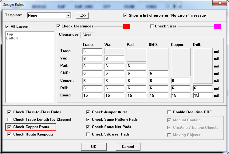
i don't know which cad tool you're using. in Eagle that would be using Polygon tool and then name your polygon to your schematic net name etc.. add a bit of isolation around your plane, it's a polygon setting,because no isolation between plane/plane or plane/route could give short during fab. -
@NeverDie
cool :)
sorry missing time, but looks good.
what you can improve a bit is for instance, giving more copper for in, switching, out.
i don't know which cad tool you're using. in Eagle that would be using Polygon tool and then name your polygon to your schematic net name etc.. add a bit of isolation around your plane, it's a polygon setting,because no isolation between plane/plane or plane/route could give short during fab. -
i was meaning drawing pours :)
-
OK, I increased the trace width on the GND, Vin, and Vout traces. Also I doubled the clearance on the copper pour. The result is Version 002, which is now posted.
-
I just now improved the project description and added the BOM.
-
I just now posted Version 3:
- I labeled each part with its component value so as to make assembly easier, and
- I cleaned up both the top and bottom silk screens.
-
I just now posted Version 4.
Changes from Version 3:
- removed unnecessary header pins,
- added more GND header pins to facilitate easier hookups, and
- made the board more compact in size.
-
I just now posted Version 5.
Changes from version 4:
- Uses same inductor as my other Linear Technology based boost converter projects.
- Enlarged PCB board to accomodate the larger design footprint.
-
I just now posted Version 6.
Changes from Version 5: removed or re-arranged silk screen to mitigate potential for solder bridging.
-
Update: the land pattern contained an error that I didn't notice until I tried to solder the chip onto the PCB. I've now fixed the problem and have now sent revised files to the fab. As with the other projects, I'll wait for the board to arrive and test that it works before I deem it no longer a work in progress.
-
I've received the board and assembled it (see photo). It appears to work in accordance with the datasheet. Therefore, this project is finished.
-
Is a schematic available?
-
Is a schematic available?
@celem said in 💬 Solar Energy Harvester:
Is a schematic available?
Yes. If you look in the photos section, it's there. It's the same as what's in the datasheet as a "typical application."
-
Hi. Do you think this will be enough for indoor usage to power a simple temperature sensor ?
What type of battery did you use this module with ? -
First time SM assembly. Photos do not show connections to 3 tiny holes that must go to ground. Is this done with small wires to side holes on either side or ...?
@mar The three tiny holes may not go to ground. They are probably 'vias' that take a trace from one side of the board to the other.
Vias are through plated at manufacture and shouldn't need anything from you.
But I don't know this particular board and so things might be different here. Use a multimeter to check the circuit diagram against the board.
Hello! It looks like you're interested in this conversation, but you don't have an account yet.
Getting fed up of having to scroll through the same posts each visit? When you register for an account, you'll always come back to exactly where you were before, and choose to be notified of new replies (either via email, or push notification). You'll also be able to save bookmarks and upvote posts to show your appreciation to other community members.
With your input, this post could be even better 💗
Register Login