[SOLVED] W5100 Ethernet gateway with RFM69 Radio fails at init
-
Hi Jonathan,
Before I show my code, please check:- Connect W5100 and radio like this
Arduino - Radio - Ethernet
13      - SCK   - SCK
12      - MISO  - MISO/SO
11      - MOSI  - MOSI/SI
10      - NSS (CS)
7       -       - SS/CS
2       - DIO0  -
Be sure to power the W5100 with 5V and the radio with 3v3!
Then, you need to modify the w5100.h file to disable radio interruption during SPI use:
Find#else inline static void initSS() { DDRB |= _BV(2); }; inline static void setSS() { PORTB &= ~_BV(2); }; inline static void resetSS() { PORTB |= _BV(2); }; #endifand replace with
#elif defined(W5100SPIPATCH)
  inline static void initSS()    { DDRD  |=  _BV(7); };
  inline static void setSS()     { cli(); PORTD &= ~_BV(7); };
  inline static void resetSS()   { PORTD |=  _BV(7); sei(); };
#endif
Then, downgrade the board manager "Arduino AVR boards" to version 1.6.11 and rebuild.
Finally, here is my working code:
/**
 * The MySensors Arduino library handles the wireless radio link and protocol
 * between your home built sensors/actuators and HA controller of choice.
 * The sensors forms a self healing radio network with optional repeaters. Each
 * repeater and gateway builds a routing tables in EEPROM which keeps track of the
 * network topology allowing messages to be routed to nodes.
 *
 * Created by Henrik Ekblad <henrik.ekblad@mysensors.org>
 * Copyright (C) 2013-2015 Sensnology AB
 * Full contributor list: https://github.com/mysensors/Arduino/graphs/contributors
 *
 * Documentation: http://www.mysensors.org
 * Support Forum: http://forum.mysensors.org
 *
 * This program is free software; you can redistribute it and/or
 * modify it under the terms of the GNU General Public License
 * version 2 as published by the Free Software Foundation.
 *
 *******************************
 *
 * REVISION HISTORY
 * Version 1.0 - Henrik EKblad
 * Contribution by a-lurker and Anticimex,
 * Contribution by Norbert Truchsess <norbert.truchsess@t-online.de>
 * Contribution by Tomas Hozza <thozza@gmail.com>
 *
 *
 * DESCRIPTION
 * The EthernetGateway sends data received from sensors to the ethernet link.
 * The gateway also accepts input on ethernet interface, which is then sent out to the radio network.
 *
 * The GW code is designed for Arduino 328p / 16MHz.  ATmega168 does not have enough memory to run this program.
 *
 * LED purposes:
 * - To use the feature, uncomment MY_DEFAULT_xxx_LED_PIN in the sketch below
 * - RX (green) - blink fast on radio message recieved. In inclusion mode will blink fast only on presentation recieved
 * - TX (yellow) - blink fast on radio message transmitted. In inclusion mode will blink slowly
 * - ERR (red) - fast blink on error during transmission error or recieve crc error
 *
 * See http://www.mysensors.org/build/ethernet_gateway for wiring instructions.
 *
 */

// Enable debug prints to serial monitor
#define MY_DEBUG

// Enable and select radio type attached
#define MY_RADIO_RFM69
#define MY_RFM69_FREQUENCY RF69_433MHZ

// La définition des PIN ci dessous n'est pas nécessaire, car c'est celle de base
//#define MY_RF69_IRQ_PIN 2
//#define MY_RF69_SPI_CS 10

// Enable gateway ethernet module type
#define MY_GATEWAY_W5100

#define MY_IP_ADDRESS 192,168,0,22
#define MY_IP_SUBNET_ADDRESS 255,255,255,0
// The port to keep open on node server mode / or port to contact in client mode
#define MY_PORT 5003

// The MAC address can be anything you want but should be unique on your network.
// Newer boards have a MAC address printed on the underside of the PCB, which you can (optionally) use.
// Note that most of the Ardunio examples use  "DEAD BEEF FEED" for the MAC address.
#define MY_MAC_ADDRESS 0xDE, 0xAD, 0xBE, 0xEF, 0xFE, 0xED

// Enable inclusion mode
#define MY_INCLUSION_MODE_FEATURE
// Enable Inclusion mode button on gateway
//#define MY_INCLUSION_BUTTON_FEATURE
// Set inclusion mode duration (in seconds)
#define MY_INCLUSION_MODE_DURATION 60
// Digital pin used for inclusion mode button
//#define MY_INCLUSION_MODE_BUTTON_PIN  3


// Flash leds on rx/tx/err
#define MY_LEDS_BLINKING_FEATURE
// Set blinking period
#define MY_DEFAULT_LED_BLINK_PERIOD 300
#define MY_DEFAULT_ERR_LED_PIN 4  // Error led pin
#define MY_DEFAULT_RX_LED_PIN  5  // Receive led pin
#define MY_DEFAULT_TX_LED_PIN  6  // Transmit led pin


#if defined(MY_USE_UDP)
  #include <EthernetUdp.h>
#endif
#include <Ethernet.h>
#include <MySensors.h>


void setup() {
}

void presentation() {
}

void loop() {
 }
}
Hope it helped
Fred@Frédéric-Grandjean Have to wait untill my level converters are arriving.. also don't have enough transistors laying around to make one my self.. did you use a level converter, probably you did?
-
Yes of course I used a level converter. Ordered the one proposed on the radio page. Works well!
-
Yes of course I used a level converter. Ordered the one proposed on the radio page. Works well!
@Frédéric-Grandjean
Hey, I'm finally working on the gateway.
But the problem is that I can't seem to find the w5100.h file.. :s
Can you maybe tell me where I can find it?Greetings
-
Yes of course I used a level converter. Ordered the one proposed on the radio page. Works well!
@Frédéric-Grandjean
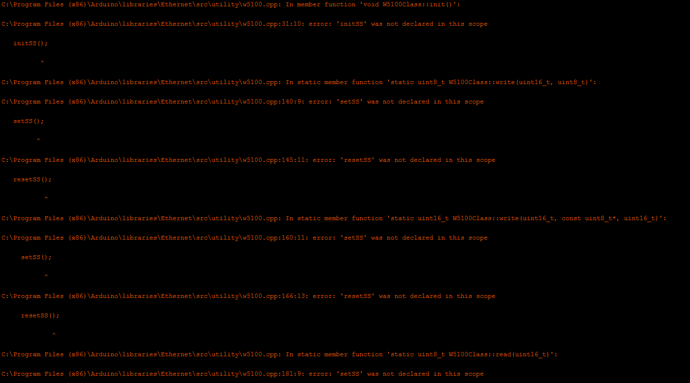
Hi again, because I'm a mac user didn't find the w5100.h file. after I took my laptop and searched for the file I found it.
after I replaced the code in the w5100.h file and changed the gateway code and complied I got these errors:
and it went on.but when I changed the code in the w5100.h file from this:
#elif defined(W5100SPIPATCH)
      inline static void initSS()    { DDRD  |=  _BV(7); };
      inline static void setSS()     { cli(); PORTD &= ~_BV(7); };
      inline static void resetSS()   { PORTD |=  _BV(7); sei(); };
    #endif
To this:
#else	//This doesn't work => elif defined(W5100SPIPATCH)
      inline static void initSS()    { DDRD  |=  _BV(7); };
      inline static void setSS()     { cli(); PORTD &= ~_BV(7); };
      inline static void resetSS()   { PORTD |=  _BV(7); sei(); };
    #endif
it compiled without any errors.
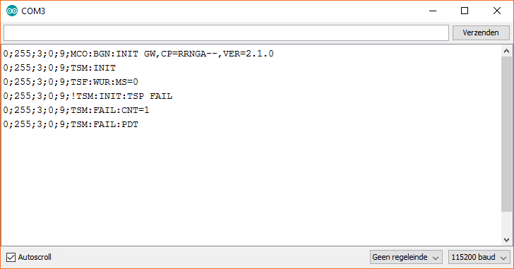
So I uploaded the code and opened the serial debugging window in which I get this:
I don't know how to fix this, do you know maybe?Thanks!!
Greetings! -
Jonathan Caes - i used your amended #else code in W5100.h file, along with wiring/pinout from Frédéric Grandjean, and example Mysensors MQTTClientGateway sketch and got a ProMiniMQTTW5100Gateway working.
You are trying Ethernet gateway (not MQTT like me), but i think you may have a radio problem - i used 10uF and 1uF caps for the RFM69 radio and separate 3.3V supply (havent tried powering radio directly from ProMini VCC though. -
@Frédéric-Grandjean
Hi again, because I'm a mac user didn't find the w5100.h file. after I took my laptop and searched for the file I found it.
after I replaced the code in the w5100.h file and changed the gateway code and complied I got these errors:
and it went on.but when I changed the code in the w5100.h file from this:
#elif defined(W5100SPIPATCH)
      inline static void initSS()    { DDRD  |=  _BV(7); };
      inline static void setSS()     { cli(); PORTD &= ~_BV(7); };
      inline static void resetSS()   { PORTD |=  _BV(7); sei(); };
    #endif
To this:
#else	//This doesn't work => elif defined(W5100SPIPATCH)
      inline static void initSS()    { DDRD  |=  _BV(7); };
      inline static void setSS()     { cli(); PORTD &= ~_BV(7); };
      inline static void resetSS()   { PORTD |=  _BV(7); sei(); };
    #endif
it compiled without any errors.
So I uploaded the code and opened the serial debugging window in which I get this:
I don't know how to fix this, do you know maybe?Thanks!!
Greetings!@Jonathan-Caes @Frédéric-Grandjean
if i use w5100 shield on uno - so i cant connect the pins how i want - means w5100 cs stays on pin 10.
what should i do? -
For W5100 shield on Uno with RF69 as a Gateway, i used:
DI00 - Pin 2
NSS - Pin 4 (3.3v level shifter)
MOSI - Pin A1 (3.3v level shifter)
MISO - Pin A2
SCK - Pin A0 (3.3v level shifter)Leave as pins 14/15/16 in MyConfig.h file - the Uno uses digital pins 14-16 physically as A0-A3.
Using a level shifter makes the ProMini more viable as it is 3.3v and you dont need a shifter.
-
Jonathan Caes - i used your amended #else code in W5100.h file, along with wiring/pinout from Frédéric Grandjean, and example Mysensors MQTTClientGateway sketch and got a ProMiniMQTTW5100Gateway working.
You are trying Ethernet gateway (not MQTT like me), but i think you may have a radio problem - i used 10uF and 1uF caps for the RFM69 radio and separate 3.3V supply (havent tried powering radio directly from ProMini VCC though.@Tris But I don't necessarily have to use the mqttw5100gateway, do I? Because I don't really know what you can do with mqtt, what the advantage is of that.
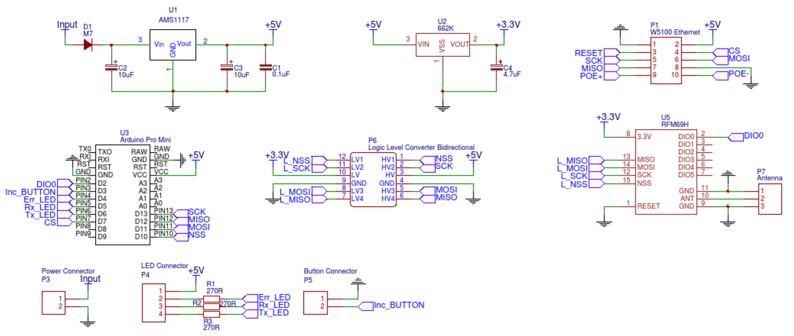
I'm also using seperate 3.3V and a 4.7µF capacitor for the radio.
Here is my schematic I used. I etched my own pcb for this and I think everything looks correct.
-
The Ethernet and MQTT wiring is the same (according to main MySesnors instructions).
As far as protocols go, I choose the MQTT route because its simple and lightwieght, tipped to be a big player in IoT.
Im not a Mysensors expert, more of a hardware guy, but briefly looking at your diagram - i havent grounded the reset pin on the RFM69 like you have.
Try cutting that track so it floats -
The Ethernet and MQTT wiring is the same (according to main MySesnors instructions).
As far as protocols go, I choose the MQTT route because its simple and lightwieght, tipped to be a big player in IoT.
Im not a Mysensors expert, more of a hardware guy, but briefly looking at your diagram - i havent grounded the reset pin on the RFM69 like you have.
Try cutting that track so it floats@Tris That can indeed be the fault, because i was looking at the hoop up page from sparfun (https://learn.sparkfun.com/tutorials/rfm69hcw-hookup-guide#hardware-overview) and thought I read that you have to connect the reset to ground, but that might be not true after reading it again. So i'll try doing that and see what happens.
Thanks!!
-
The Ethernet and MQTT wiring is the same (according to main MySesnors instructions).
As far as protocols go, I choose the MQTT route because its simple and lightwieght, tipped to be a big player in IoT.
Im not a Mysensors expert, more of a hardware guy, but briefly looking at your diagram - i havent grounded the reset pin on the RFM69 like you have.
Try cutting that track so it floats@Tris Cut the reset connection and tried again, did not work.. still getting the same debugging info.. :(
-
The Ethernet and MQTT wiring is the same (according to main MySesnors instructions).
As far as protocols go, I choose the MQTT route because its simple and lightwieght, tipped to be a big player in IoT.
Im not a Mysensors expert, more of a hardware guy, but briefly looking at your diagram - i havent grounded the reset pin on the RFM69 like you have.
Try cutting that track so it floats@Tris I also get the same debugging when using the MQTTclientgateway..
-
Only thing i can think of, is quite basic but i do it myself quite often.
Remember to put the // lines back infront of the soft spi line in MyConfig.h file.
You only need that for NRF24 W5100 setupAlso define the new MI/MO/SCK pins in the sketch
#define MY_SOFT_SPI_SCK_PIN 13 #define MY_SOFT_SPI_MISO_PIN 12 #define MY_SOFT_SPI_MOSI_PIN 11``` -
Only thing i can think of, is quite basic but i do it myself quite often.
Remember to put the // lines back infront of the soft spi line in MyConfig.h file.
You only need that for NRF24 W5100 setupAlso define the new MI/MO/SCK pins in the sketch
#define MY_SOFT_SPI_SCK_PIN 13 #define MY_SOFT_SPI_MISO_PIN 12 #define MY_SOFT_SPI_MOSI_PIN 11```@Tris This is the code I used, it was sugested by Frédéric. With this I don't need to change anything to the myconfig.h file, or do I?
/** * The MySensors Arduino library handles the wireless radio link and protocol * between your home built sensors/actuators and HA controller of choice. * The sensors forms a self healing radio network with optional repeaters. Each * repeater and gateway builds a routing tables in EEPROM which keeps track of the * network topology allowing messages to be routed to nodes. * * Created by Henrik Ekblad <henrik.ekblad@mysensors.org> * Copyright (C) 2013-2015 Sensnology AB * Full contributor list: https://github.com/mysensors/Arduino/graphs/contributors * * Documentation: http://www.mysensors.org * Support Forum: http://forum.mysensors.org * * This program is free software; you can redistribute it and/or * modify it under the terms of the GNU General Public License * version 2 as published by the Free Software Foundation. * ******************************* * * REVISION HISTORY * Version 1.0 - Henrik EKblad * Contribution by a-lurker and Anticimex, * Contribution by Norbert Truchsess <norbert.truchsess@t-online.de> * Contribution by Tomas Hozza <thozza@gmail.com> * * * DESCRIPTION * The EthernetGateway sends data received from sensors to the ethernet link. * The gateway also accepts input on ethernet interface, which is then sent out to the radio network. * * The GW code is designed for Arduino 328p / 16MHz. ATmega168 does not have enough memory to run this program. * * LED purposes: * - To use the feature, uncomment MY_DEFAULT_xxx_LED_PIN in the sketch below * - RX (green) - blink fast on radio message recieved. In inclusion mode will blink fast only on presentation recieved * - TX (yellow) - blink fast on radio message transmitted. In inclusion mode will blink slowly * - ERR (red) - fast blink on error during transmission error or recieve crc error * * See http://www.mysensors.org/build/ethernet_gateway for wiring instructions. * */ // Enable debug prints to serial monitor #define MY_DEBUG // Enable and select radio type attached #define MY_RADIO_RFM69 #define MY_RFM69_FREQUENCY RF69_433MHZ // La définition des PIN ci dessous n'est pas nécessaire, car c'est celle de base //#define MY_RF69_IRQ_PIN 2 //#define MY_RF69_SPI_CS 10 // Enable gateway ethernet module type #define MY_GATEWAY_W5100 #define MY_IP_ADDRESS 192,168,0,22 #define MY_IP_SUBNET_ADDRESS 255,255,255,0 // The port to keep open on node server mode / or port to contact in client mode #define MY_PORT 5003 // The MAC address can be anything you want but should be unique on your network. // Newer boards have a MAC address printed on the underside of the PCB, which you can (optionally) use. // Note that most of the Ardunio examples use "DEAD BEEF FEED" for the MAC address. #define MY_MAC_ADDRESS 0xDE, 0xAD, 0xBE, 0xEF, 0xFE, 0xED // Enable inclusion mode #define MY_INCLUSION_MODE_FEATURE // Enable Inclusion mode button on gateway //#define MY_INCLUSION_BUTTON_FEATURE // Set inclusion mode duration (in seconds) #define MY_INCLUSION_MODE_DURATION 60 // Digital pin used for inclusion mode button //#define MY_INCLUSION_MODE_BUTTON_PIN 3 // Flash leds on rx/tx/err #define MY_LEDS_BLINKING_FEATURE // Set blinking period #define MY_DEFAULT_LED_BLINK_PERIOD 300 #define MY_DEFAULT_ERR_LED_PIN 4 // Error led pin #define MY_DEFAULT_RX_LED_PIN 5 // Receive led pin #define MY_DEFAULT_TX_LED_PIN 6 // Transmit led pin #if defined(MY_USE_UDP) #include <EthernetUdp.h> #endif #include <Ethernet.h> #include <MySensors.h> void setup() { } void presentation() { } void loop() { } } -
@Tris
ok it didnt work with the w5100.h amendment, so i reverted to the original config.
now im on your new pinout with the a0-a2 thing, and i got identification on domoticz log and ping throught win7 command line. everything looks fine, but when i try mockmysensors to see if it recieves any comminication i dont see anything.
also the serial log looks wierd:IP: 192.168.254.204 0;255;3;0;9;MCO:BGN:STP 0;255;3;0;9;MCO:BGN:INIT OK,TSP=1 0;255;3;0;9;Eth: connect 0;255;3;0;9;Eth: 0;0;3;0;2; 0;255;3;0;9;Eth: 0;0;3;0;2;Get Version 0;255;3;0;9;Eth: 0;0;3;0;18;PING 0;255;3;0;9;Eth: 0;0;3;0;18;PING 0;255;3;0;9;Eth: 0;0;3;0;18;PING 0;255;3;0;9;Eth: 0;0;3;0;18;PING 0;255;3;0;9;Eth: 0;0;3;0;18;PINGand it goes on and on...
of course both nodes have gone eeprom clearing