"Choose the Serial Port" error with MySensors and RFXtrx433?
-
Hmm... I'm using the vanilla version av the gateway. Measured the power consumption and the powered USB hub should be able to provide enough power for both devices. There must be some configuration error, but I can't figure out what. The Vera can use both the RFXtrx and a USB drive (for logs) at the same time, also using the single USB port with a powered hub.
I don't have the technological skill to troubleshoot this, but until you can confirm there is another user that have gotten Vera to work with both a connected RFXtrx AND MySensors gateway this seems to be an issue.
@Aron-Sjöberg Did you solve your problem? I have a mysensors serial gateway, a rfxtrx433e and a USB stick connected to my Vera (Edge) through an externally powered USB hub (plexgear). They all work just fine.
-
Do you have this one?
I don`t have a second hub to try with so I need to buy a new one...
-
No, still have the same issue with port conflict with the RFXtrx... :(
I'm going to try another hub and build the serial gateway again.
-
Argh!
I finally received my new USB-hub and tried a new serial gateway I built.
I STILL get the same error. I can't seem to have both my RFXtrx433E and the MySensor gateway connected (and working) at the same time.
@Magnus, could you post a screenshot of your settings in Vera Edge?
-
I bought this one: https://www.kjell.com/se/sortiment/dator-natverk/datortillbehor/usb-tillbehor/usb-hubbar/plexgear-usb-hubb-7-vags-med-stromforsorjning-p68616
Now all is working fine for me.
-
Argh!
I finally received my new USB-hub and tried a new serial gateway I built.
I STILL get the same error. I can't seem to have both my RFXtrx433E and the MySensor gateway connected (and working) at the same time.
@Magnus, could you post a screenshot of your settings in Vera Edge?
-
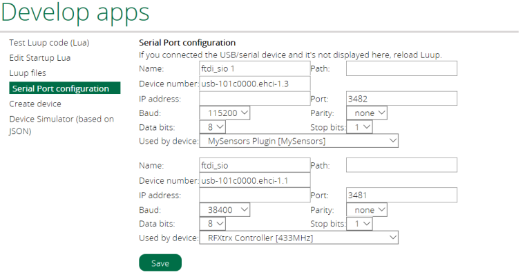
@Aron-Sjöberg
My config below:
-
@Magnus just a wild guess.
Did you try to compile the MySensors GW with baudrate set to 38400 so they both use the same baudrate?
@BartE Hmm... I didn't know you could choose the baudrate? I just followed the instructions on the website (https://www.mysensors.org/build/serial_gateway) but when I check the code I can clearly read that there is something in the sketch about the baud rate:
// Define a lower baud rate for Arduino's running on 8 MHz (Arduino Pro Mini 3.3V & SenseBender)
#if F_CPU == 8000000L
#define MY_BAUD_RATE 38400
#endif
However, I use the recommended Arduino Nano for my Vera Serial Gateway, not Arduino Pro Mini 3.3V or SenseBender.
How would I change the baud rate for the MySensor gateway if I can't use 38400 because it is used by my RFXtrx433E?
-
@Aron-Sjöberg
My config below:
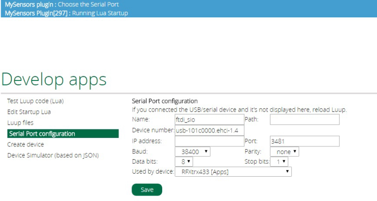
@Magnus Thank you for your trouble! Did you photoshop your screenshot or can you configure two different serial port devices at the same time? I only have one instance I can change settings for?
Otherwise my settings seems to be the same as yours.
-
@BartE Hmm... I didn't know you could choose the baudrate? I just followed the instructions on the website (https://www.mysensors.org/build/serial_gateway) but when I check the code I can clearly read that there is something in the sketch about the baud rate:
// Define a lower baud rate for Arduino's running on 8 MHz (Arduino Pro Mini 3.3V & SenseBender)
#if F_CPU == 8000000L
#define MY_BAUD_RATE 38400
#endif
However, I use the recommended Arduino Nano for my Vera Serial Gateway, not Arduino Pro Mini 3.3V or SenseBender.
How would I change the baud rate for the MySensor gateway if I can't use 38400 because it is used by my RFXtrx433E?
@Aron-Sjöberg said in "Choose the Serial Port" error with MySensors and RFXtrx433?:
Add this line
#define MY_BAUD_RATE 38400above the #include <SPI.h>
-
Have you restart luup after you connected both usb-ports?
-
@Magnus Thank you for your trouble! Did you photoshop your screenshot or can you configure two different serial port devices at the same time? I only have one instance I can change settings for?
Otherwise my settings seems to be the same as yours.
@Aron-Sjöberg I can configure both ports at the same time. It looks exactly as in the posted picture.
@BartE I justfollowed the instructions on the website. This was probably a year ago and the code used for the serial GW was designed only for Arduino Nano 328p / 16MHz.
-
Thank you for your help!
Unfortunately nothing works. I have even tried to change the radio module from RFM69 to NRF24L01 to make sure it wasn't the connections that was badly soldered.
@Magnus Could you please post the sketch you use for your gateway? I tried to add #define MY_BAUD_RATE 38400 as @BartE suggested but this doesn't seem to make a difference.
I'm starting to think there is something wrong on Veras end. I don't get two different devices under the Serial Port configuration like @Magnus. You also have different ports (3482 for the serial gateway and 3481 for the RFXtrx).
As a last resort I guess I could install Domoticz on a RPi and import the devices to the Vera as virtual devices, but this seems like a hassle if it is possible for the gateway to work directly.
-
Have you ever confirmed that the MySensors USB gateway works without the RFXtrx attached? Or checked that you really have an FTDI chip on the MySensors USB gateway? This is the only chip that the Vera can detect out of the box. A complete reboot of your Vera might also help.
-
I'm using a Arduino Nano. How do I check if it is a genuine FTDI chip?
-
I'm using a Arduino Nano. How do I check if it is a genuine FTDI chip?
@Aron-Sjöberg the FTDI chip is on the under side of Arduino nanos and clearly sais FTDI. Please post pictures of your devise if your uncertain. I don't know if fake or real maters when used on Vera.
-
@korttoma said in "Choose the Serial Port" error with MySensors and RFXtrx433?:
Arduino nanos
It's a bit hard to read but the black chips on the back says:
A106and
WCH
CH340G
202686635
and
AMS1117
5.0 DN628
on the front (where the button is)
ALMEL
MEGA328P
AU 1639
I can't find any mention of "FTDI". Should I assume it is not a genuine Arduino nano?
I DO have an unused Arduino Uno laying around. Maybe it would be easier to buy a ethernet shield and use a ethernet gateway instead of the serial gateway? Is it a W5100 ethernet shield I would need for the Uno?
@Aron-Sjöberg I would guess the problems are due to the CH340G chip (instead of an FTDI chip). I use this nano for my gateway:
https://www.aliexpress.com/item/Nano-V3-0-Mini-USB-ATmega328-5V-16M-100-ORIGINAL-FTDI-FT232RL/32338360936.html?spm=2114.13010608.0.0.ZU4WHD -
@korttoma said in "Choose the Serial Port" error with MySensors and RFXtrx433?:
Arduino nanos
It's a bit hard to read but the black chips on the back says:
A106and
WCH
CH340G
202686635
and
AMS1117
5.0 DN628
on the front (where the button is)
ALMEL
MEGA328P
AU 1639
I can't find any mention of "FTDI". Should I assume it is not a genuine Arduino nano?
I DO have an unused Arduino Uno laying around. Maybe it would be easier to buy a ethernet shield and use a ethernet gateway instead of the serial gateway? Is it a W5100 ethernet shield I would need for the Uno?
@Aron-Sjöberg Used sketch below, I didn't make any changes to the original sketch:
/**
 * The MySensors Arduino library handles the wireless radio link and protocol
 * between your home built sensors/actuators and HA controller of choice.
 * The sensors forms a self healing radio network with optional repeaters. Each
 * repeater and gateway builds a routing tables in EEPROM which keeps track of the
 * network topology allowing messages to be routed to nodes.
 *
 * Created by Henrik Ekblad <henrik.ekblad@mysensors.org>
 * Copyright (C) 2013-2015 Sensnology AB
 * Full contributor list: https://github.com/mysensors/Arduino/graphs/contributors
 *
 * Documentation: http://www.mysensors.org
 * Support Forum: http://forum.mysensors.org
 *
 * This program is free software; you can redistribute it and/or
 * modify it under the terms of the GNU General Public License
 * version 2 as published by the Free Software Foundation.
 *
 *******************************
 *
 * DESCRIPTION
 * The ArduinoGateway prints data received from sensors on the serial link.
 * The gateway accepts input on seral which will be sent out on radio network.
 *
 * The GW code is designed for Arduino Nano 328p / 16MHz
 *
 * Wire connections (OPTIONAL):
 * - Inclusion button should be connected between digital pin 3 and GND
 * - RX/TX/ERR leds need to be connected between +5V (anode) and digital pin 6/5/4 with resistor 270-330R in a series
 *
 * LEDs (OPTIONAL):
 * - To use the feature, uncomment WITH_LEDS_BLINKING in MyConfig.h
 * - RX (green) - blink fast on radio message recieved. In inclusion mode will blink fast only on presentation recieved
 * - TX (yellow) - blink fast on radio message transmitted. In inclusion mode will blink slowly
 * - ERR (red) - fast blink on error during transmission error or recieve crc error
 *
 */

#define NO_PORTB_PINCHANGES

#include <MySigningNone.h>
#include <MyTransportRFM69.h>
#include <MyTransportNRF24.h>
#include <MyHwATMega328.h>
#include <MySigningAtsha204Soft.h>
#include <MySigningAtsha204.h>

#include <SPI.h>
#include <MyParserSerial.h>
#include <MySensor.h>
#include <stdarg.h>
#include <PinChangeInt.h>
#include "GatewayUtil.h"

#define INCLUSION_MODE_TIME 1 // Number of minutes inclusion mode is enabled
#define INCLUSION_MODE_PIN  3 // Digital pin used for inclusion mode button
#define RADIO_ERROR_LED_PIN 4  // Error led pin
#define RADIO_RX_LED_PIN    6  // Receive led pin
#define RADIO_TX_LED_PIN    5  // the PCB, on board LED

// NRFRF24L01 radio driver (set low transmit power by default)
MyTransportNRF24 transport(RF24_CE_PIN, RF24_CS_PIN, RF24_PA_LEVEL_GW);
//MyTransportRFM69 transport;

// Message signing driver (signer needed if MY_SIGNING_FEATURE is turned on in MyConfig.h)
//MySigningNone signer;
//MySigningAtsha204Soft signer;
//MySigningAtsha204 signer;

// Hardware profile
MyHwATMega328 hw;

// Construct MySensors library (signer needed if MY_SIGNING_FEATURE is turned on in MyConfig.h)
// To use LEDs blinking, uncomment WITH_LEDS_BLINKING in MyConfig.h
#ifdef WITH_LEDS_BLINKING
MySensor gw(transport, hw /*, signer*/, RADIO_RX_LED_PIN, RADIO_TX_LED_PIN, RADIO_ERROR_LED_PIN);
#else
MySensor gw(transport, hw /*, signer*/);
#endif

char inputString[MAX_RECEIVE_LENGTH] = "";    // A string to hold incoming commands from serial/ethernet interface
int inputPos = 0;
boolean commandComplete = false;  // whether the string is complete

void parseAndSend(char *commandBuffer);

void output(const char *fmt, ... ) {
   va_list args;
   va_start (args, fmt );
   vsnprintf_P(serialBuffer, MAX_SEND_LENGTH, fmt, args);
   va_end (args);
   Serial.print(serialBuffer);
}


void setup()
{
  gw.begin(incomingMessage, 0, true, 0);

  setupGateway(INCLUSION_MODE_PIN, INCLUSION_MODE_TIME, output);

  // Add interrupt for inclusion button to pin
  PCintPort::attachInterrupt(pinInclusion, startInclusionInterrupt, RISING);


  // Send startup log message on serial
  serial(PSTR("0;0;%d;0;%d;Gateway startup complete.\n"),  C_INTERNAL, I_GATEWAY_READY);
}

void loop()
{
  gw.process();

  checkButtonTriggeredInclusion();
  checkInclusionFinished();

  if (commandComplete) {
    // A command wass issued from serial interface
    // We will now try to send it to the actuator
    parseAndSend(gw, inputString);
    commandComplete = false;
    inputPos = 0;
  }
}


/*
  SerialEvent occurs whenever a new data comes in the
 hardware serial RX.  This routine is run between each
 time loop() runs, so using delay inside loop can delay
 response.  Multiple bytes of data may be available.
 */
void serialEvent() {
  while (Serial.available()) {
    // get the new byte:
    char inChar = (char)Serial.read();
    // if the incoming character is a newline, set a flag
    // so the main loop can do something about it:
    if (inputPos<MAX_RECEIVE_LENGTH-1 && !commandComplete) {
      if (inChar == '\n') {
        inputString[inputPos] = 0;
        commandComplete = true;
      } else {
        // add it to the inputString:
        inputString[inputPos] = inChar;
        inputPos++;
      }
    } else {
       // Incoming message too long. Throw away
        inputPos = 0;
    }
  }
}