Power pulse meter inside fuse box cabinet
-
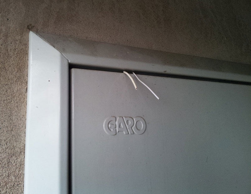
So, I was thinking of expanding the sensor network a bit to include the pulse power meter. Only problem is the power meter is located inside one of these metal cabinets on the outside of the house:

Which in turn is inside a thick wall of clay aggregate (very popular around these parts). I have no exposed power outlets inside the cabinet nor can I expect reception since I just tested and don't have reception broadcasting from outside the cabinet. The latter could probably be tweaked, even moving to the LNA+PA if needed, but I still can't expect to have any communication inside the cabinet.The main problem is still power though. Even thought about making a coil around some exposed phase and effectively steal power, but it seems like an overly complicated solution that would at the very least require a lot of wire and work.
I could drill a small hole through the front but I doubt the electrical company would very much appreciate this either.
I looked at how some commercial solutions worked, including the EnergyWatch that Vattenfall sells, and they somehow manage WIFI without sleeping (able to measure both real-time W and kWh) on 3 x D (R20) batteries. That is like 15000mAh to work with. But seeing as alkaline D cells are a bit more expensive, it would probably make sense to use mains power instead. It might a good place to put a whole cluster of sensors nearby, including the inevitable repeater node.
Ideas?
@bjornhallberg I guess you expect a regular battery powered sensor to die pretty soon when it wakes for every pulse.
If your wake/count/sleep cycle is very short it could be possible...
Or, if you're handy with electronics, a separate low power counter IC could be added which only does the counting, and read this counter value from your sensor every minute or so. -
There may be a more low-tech solution for this that I should have considered first :flushed:
Turns out there is a considerable gap in-between the door and cabinet. So running 12V or 5V or whatever inside the cabinet should be easy. Or running some extension cables to the LM393 and keeping the arduino outside. A meter or two of reasonable gauge wire shouldn't hurt the signal since it is only high/low? -
I looked at how some commercial solutions worked, including the EnergyWatch that Vattenfall sells, and they somehow manage WIFI without sleeping (able to measure both real-time W and kWh) on 3 x D (R20) batteries.
Is the WiFi unit within the box?? Would think that can not work, the box is more or less like a cage of Faraday so 2.4 GHz signals can not enter/escape.
So running 12V or 5V or whatever inside the cabinet should be easy. Or running some extension cables to the LM393 and keeping the arduino outside. A meter or two of reasonable gauge wire shouldn't hurt the signal since it is only high/low?
Your are going a bit too fast for me to understand your planned setup. What is the LM393 doing and is with this plan your sensor outside?
-
I looked at how some commercial solutions worked, including the EnergyWatch that Vattenfall sells, and they somehow manage WIFI without sleeping (able to measure both real-time W and kWh) on 3 x D (R20) batteries.
Is the WiFi unit within the box?? Would think that can not work, the box is more or less like a cage of Faraday so 2.4 GHz signals can not enter/escape.
So running 12V or 5V or whatever inside the cabinet should be easy. Or running some extension cables to the LM393 and keeping the arduino outside. A meter or two of reasonable gauge wire shouldn't hurt the signal since it is only high/low?
Your are going a bit too fast for me to understand your planned setup. What is the LM393 doing and is with this plan your sensor outside?
@daulagari Regarding the Vattenfall meter I would think that given the long cable between the sensor and the battery/microcontroller box it would also be on the outside.
Well, I was just thinking of doing the same with the LM393, having it on a long cord so I wont have to wrestle with the signal inside the cabinet. If there is any voltage drop to speak of because of the wire I could always feed it 5V and have logic level converter on the return signal since all the APMs I have are 3.3V.
-
Also, another question: Would it be possible to use the RTC module (DS3231) from the display and time sketch to run the sensor on batteries and still get Watt-values? I understand the problem was with millis() incrementation .... could the RTC solve this reliably or is it not precise enough in its time-keeping and how it reports time?
I mean, I'm more or less set on powering this sensor from mains to get both W and kWh, but I'd still be nice to have options.
-
you could call an electrician an install a fuse and poweroutlet to the left of the main switch.
underneath there should be a din rail.
Only the antenna needs to be outside of the cabinet. -
you could call an electrician an install a fuse and poweroutlet to the left of the main switch.
underneath there should be a din rail.
Only the antenna needs to be outside of the cabinet.@Mrlynx said:
you could call an electrician an install a fuse and poweroutlet to the left of the main switch.
underneath there should be a din rail.
Only the antenna needs to be outside of the cabinet.This is what I would recommend also (fuse and outlet on the din rail). And then have your node device outside and only run power and sensor wires through the gap in the door (this is how I do it to).
-
you could call an electrician an install a fuse and poweroutlet to the left of the main switch.
underneath there should be a din rail.
Only the antenna needs to be outside of the cabinet.@Mrlynx, @korttoma Yeah I guess that would work, and I might just do that if I have an electrician over for some other business. Having an outlet there might make things easier for future appliances that might want to reside there.
But it so happens I have an outlet just some 3 meters away from the cabinet. Safe from the elements. I thought I might make this a central power access point for the whole front of the house, using some sort of 12V outdoor adapter that in turn runs cables to any number of sensors. Shouldn't really matter how many volts are lost in transfer, and then I could finish off with either connecting the RAW pin OR using one of those neat buck converters that can be found cheaply on Ebay. I have a couple of them already and used them to power a sensor node and at least with a decoupling capacitor on the radio they don't seem to be too bad.
-
@bjornhallberg said:
Just curious, what brand and model is the power utility meter in the box?
I'm thinking of "hacking" mine (there is an optical communication port on it), so with proper hw / software, i maybe be able to ask the meter for the values.)
Btw. mine is from Kamstrup (can't remember the model).
@tbowmo It's a Landis+Gyr Domestic.
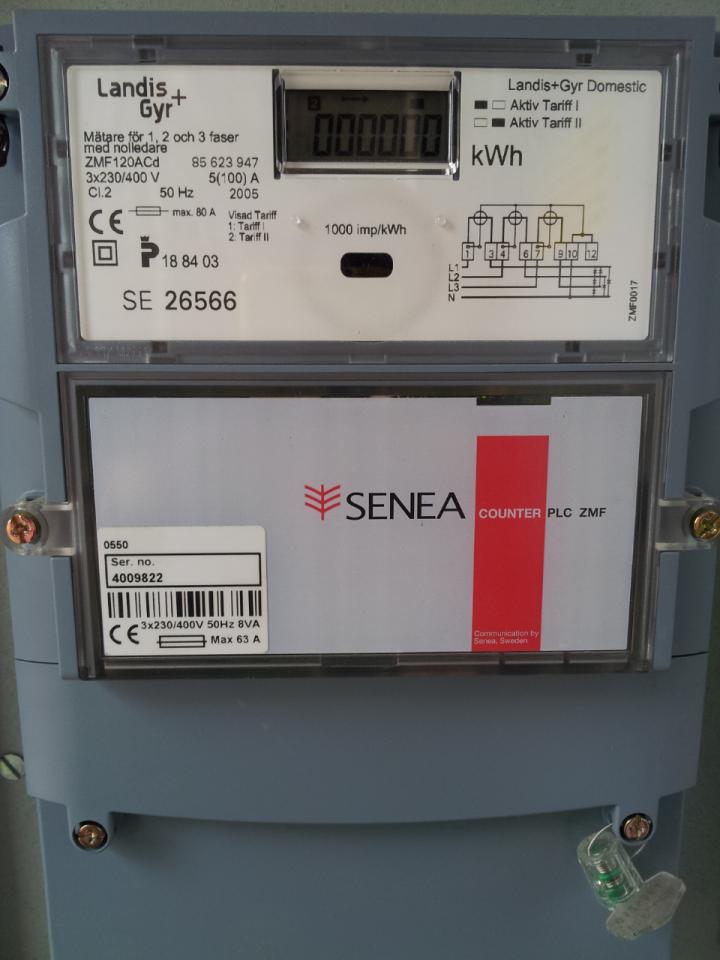
No optic port on mine that I've found. Having one could open up a lot more possibilities.No way to get into the meter without breaking the seal, but I assume that the Senea Counter module for remote reading (Senea is now owned by Kamstrup are they not?) could theoretically offer some interesting info. I think some of these modules not only store energy and and watt readings but also a log of the last couple of power outages.
On a side note ... not sure how this module communicates is data back to the power company but I assume it's via the power lines (?). It's on my to-do list to look into whether these remote controlled boxes actually introduce any significant interference back into the power grid. I saw some grumblings on another forum but it could just be bad science as far as I know.
-
I think that the window below the display is the optical communication port. Searching the net I found this http://www.landisgyr.com/product/ansi-iec-optical-probe-aip200/
And it seems like they are following the ansi-iec standard..
-
I think that the window below the display is the optical communication port. Searching the net I found this http://www.landisgyr.com/product/ansi-iec-optical-probe-aip200/
And it seems like they are following the ansi-iec standard..
@tbowmo Nice find! I wonder if this is worth looking into. If it could ask for data instead of just count blinks it would be a great deal more helpful. I assume you could buy an equivalent reader from Ebay or build one yourself without too much hassle?
-
Have a look at this http://ing.dk/blog/hvilken-elmaaler-har-du-120890#p391493
There is a schematic of a IR head for the kamstrup meters. Might be usefull for your meter as well..
If you're up to reading danish, there are a couple of sites where the author of that blog deciphers the kamstrup protocol..
like this one http://ing.dk/blog/kamstrup-meter-protocol-127052
Hello! It looks like you're interested in this conversation, but you don't have an account yet.
Getting fed up of having to scroll through the same posts each visit? When you register for an account, you'll always come back to exactly where you were before, and choose to be notified of new replies (either via email, or push notification). You'll also be able to save bookmarks and upvote posts to show your appreciation to other community members.
With your input, this post could be even better 💗
Register Login