Gas Meter Reading Using a Magnetometer
-
@dpcr Very nice project and creative use of a magnetometer!
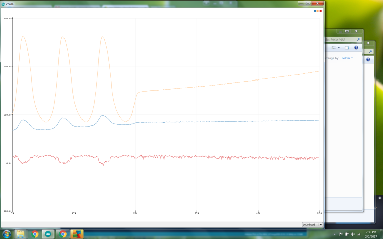
These things are very cheap and able to solve far more problems than just telling in what direction you're heading ;-)Could you post a shot of some of the sine data from the serial plotter? Just wondering what it looks like.
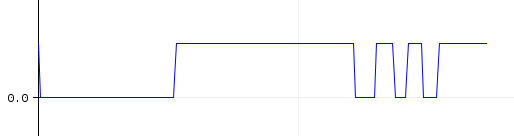
Any idea about the resolution you get with this method? You describe half a sine to be divided in 10 steps, but how much gas usage does one sine represent?@Yveaux ! The picture shows the sine wave produced by the HMC5883L. The orange line is the Y axis, which is the one I am using. The large visible sine wave is when the gas is flowing for the furnace. When the gas stops the line is creeping upwards, this is the pilot light on the water heater.
-
@ThomasDr do I understand it correctly that you get a full sine swing for each 0.001 m3 of gas usage?
@Yveaux Not quite. What I did was look at the actual gas meter and determine how many full "cycles" of the sign wave I received for 2 CuFt. What I got was 16 full cycles per 2 CuFt. I then divided that by 2 to get how many cycles per CuFt (8). Then I divided that by the number of divisions per one full cycle (20), 10 from TOP to BOTTOM and 10 from BOTTOM to TOP. This gave me the the CuFt of gas used per division or pulse. I then converted that to litre. This gave me the 0.17698 per litre. Hope this help and I hope my math is correct.
-
@ThomasDr do I understand it correctly that you get a full sine swing for each 0.001 m3 of gas usage?
-
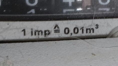
@Yveaux Sorry, it is 1 puls at 0.01 m3
That depends on the gas meter you use, the BK4 gives a magnetic pulse per 0.01 m3.
For this puls you can use a reed contact or a magnetometer.
regards
ThomasD@dpcr Thanks for the nice chart!
It is indeed a clear sine wave. Having the sensor run for a while and checking with the actual meter counts will prove if your math was correct ;-)
You could also use inverse sine to calculate the angle of the sine pulse, to have linear readout and probably even increase resolution.@ThomasDr I'm currently using a pulse counter (reed contact) to count the pulses of my meter (also 100/m3).
Works well, but the magnetometer has the potential to increase the measurement resolution. -
Sorry for the question, but why would you need a magnetometer to have better resolution in the measurements when you only need to count pulses? Given of course that the reed switch provides accurate readings, because if it doesn't then I understand why to use the magnetometer
-
Sorry for the question, but why would you need a magnetometer to have better resolution in the measurements when you only need to count pulses? Given of course that the reed switch provides accurate readings, because if it doesn't then I understand why to use the magnetometer
@gohan well, it seems like a magnetometer is able to also give detailed information inbetween the pulses.
For a pulse counter you only see a complete revolution as a single pules; it doesn't tell you how far the revolution is. The magnetometer creates a sine signal, which indicates where you are on this single revolution. -
I can see that, but looking at the graph if that climbing line is just the consumption of the pilot light, how would you benefit for this added resolution? I am just referring to the fact that this kind of sensor is used to keep track of gas usage during the day and not a live view of the actual flow even for the small amounts: we are talking 0.01 cubic meter for each pulse and a pilot light usually uses 3 cubic meters per hour, so we end up with a pulse every the 10-15 seconds and to me it seems a good resolution, or maybe I just don't see what are other possible benefits.
-
Sorry for the question, but why would you need a magnetometer to have better resolution in the measurements when you only need to count pulses? Given of course that the reed switch provides accurate readings, because if it doesn't then I understand why to use the magnetometer
@gohan I had to use a magnetometer because my meter did not have a magnet in it. I tried a reed switch but it never actuated and my meter is outside. So I was stuck using a magnetometer which I mounted in a water proof plastic box. The issue I had was getting the sine wave to create a pulse that was usable for MySensors. I did look at using an inverse sine, or as someone else mentioned, use an exponential moving average of the data but they both failed. When the gas stops flowing, a pilot light as an example as seen in the attached picture, there is little to no gas flowing so the angle doesn't change much. It looks like no gas is flowing when it actually is. I decided to go with dividing the wave or meter movement into separate divisions to create a more accurate way of measuring the gas flow in all flow situations.
I haven't had a chance to test the accuracy of my math against the gas meter but I will at some point. The issue I'm currently having is that the bellows inside of the meter that the magnetometer is reading do not move at the same rate at all times. This causes the FLOW output to change when I know the gas is flowing at a steady rate. The VOLUME doesn't seem to be effected too much. So what I did was to take a moving average of the last three FLOW readings. This helps a little.
The hardware and ideas were done by me but the coding was done by my 24 year old son. I always enjoy a challenge. Please feel free to comment.
-
Ok, now it makes sense. If you plot the data with the pilot using the gas, don't you still see a sine wave but with, of course, a longer period?
-
Ok, now it makes sense. If you plot the data with the pilot using the gas, don't you still see a sine wave but with, of course, a longer period?
@gohan Yes you do, but what about the times when there is gas flowing. If I remember correctly there was about 20 or 25 minutes for full sine wave when only the pilot was running. That SEND_FREQUENCY (1500000) was too large when the gas was actually flowing to get an accurate measurement. I just wanted to get an accurate reading of the gas flow at all flow rates. Am I missing something?
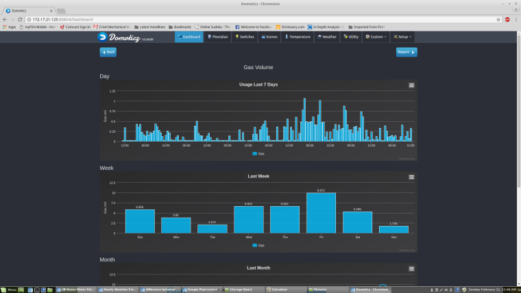
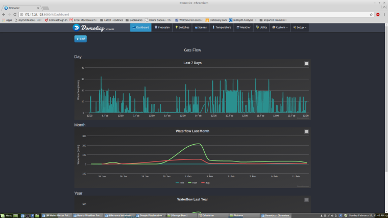
Here are some screenshots from Domoticz for the past week:
 )
) -
Sorry for the question, but why would you need a magnetometer to have better resolution in the measurements when you only need to count pulses? Given of course that the reed switch provides accurate readings, because if it doesn't then I understand why to use the magnetometer
-
@gohan Hello,
My thought is simpler.
The original sensor is too expensive.
With a Reedcontact I must find the right position.
The magnetometer I could simply attach somewhere in the proximity.regards
ThomasD -
Hello,
here my sketch to form a puls:
/***************************************************************************
  This is a library example for the HMC5883 magnentometer/compass

  Designed specifically to work with the Adafruit HMC5883 Breakout
  http://www.adafruit.com/products/1746

  *** You will also need to install the Adafruit_Sensor library! ***

  These displays use I2C to communicate, 2 pins are required to interface.

  Adafruit invests time and resources providing this open source code,
  please support Adafruit andopen-source hardware by purchasing products
  from Adafruit!

  Written by Kevin Townsend for Adafruit Industries with some heading example from
  Love Electronics (loveelectronics.co.uk)

 This program is free software: you can redistribute it and/or modify
 it under the terms of the version 3 GNU General Public License as
 published by the Free Software Foundation.

 This program is distributed in the hope that it will be useful,
 but WITHOUT ANY WARRANTY; without even the implied warranty of
 MERCHANTABILITY or FITNESS FOR A PARTICULAR PURPOSE.  See the
 GNU General Public License for more details.

 You should have received a copy of the GNU General Public License
 along with this program.  If not, see <http://www.gnu.org/licenses/>.

 ***************************************************************************/

#include <Wire.h>
#include <Adafruit_Sensor.h>
#include <Adafruit_HMC5883_U.h>

/* Assign a unique ID to this sensor at the same time */
Adafruit_HMC5883_Unified mag = Adafruit_HMC5883_Unified(12345);

unsigned long t = 0;
unsigned long counter = 0;
bool trigger = 0;
float out = 0.0;

void setup(void)
{
  Serial.begin(115200);
  //Serial.println("HMC5883 Magnetometer Test"); Serial.println("");

  /* Initialise the sensor */
  if(!mag.begin())
  {
    /* There was a problem detecting the HMC5883 ... check your connections */
    Serial.println("Ooops, no HMC5883 detected ... Check your wiring!");
    while(1);
  }

  /* Display some basic information on this sensor */
  // displaySensorDetails();
}

void loop(void)
{
  /* Get a new sensor event */
  sensors_event_t event;
  mag.getEvent(&event);

  /* Display the results (magnetic vector values are in micro-Tesla (uT)) */
  out = event.magnetic.y;
  if (out > -0.7 && trigger == 0)
  {
  trigger = 1;
  Serial.println(trigger);
  }
  if (out < -110.5 && trigger == 1)
  {
  trigger = 0;
  counter++;
  Serial.println(trigger);
  }

  if (millis() > (t+5000))
   {
   Serial.println(trigger);
   t = millis();
   }


  delay(250);
}
And here the Output, 1 Puls is 0.001 m3, first at slow flow and then with my max.
regards
ThomasD@ThomasDr Sorry not to get back to you when I saw your post, your project looks interesting. Does the HMC5983 magnetometer output something similar to the HMC5883L? I just used the HMC5883L magnetometer because I found it useful, I didn't run across it during my research.
-
Ran into a problem. The magnetism value changes when the outside air temperature changes which causes many incorrect readings. So my initial sketch that finds the TOP and BOTTOM of the wave is having problems so I'm in the process of trying to find another way to get some useful data out of the magnetometer. Any ideas?
-
-
If you find a correlation between temperature and change of magnetic field, maybe you could add a thermistore and use it to compute a correction coefficient.
Or maybe even a second magnetometer with a fixed magnet to use as reference 🤔@gohan Thanks, that was what I thought initially but the changes in the magnetic forces were all over the place but did seem to coincide with the outdoor temperature. They were relatively small in comparison to the total but enough the cause problems. It was almost like the meter itself was doing this?? Since we rely so heavily on the Top and Bottom magnetic readings to not only find the top and the bottom of the "wave" but to also calculate the intervals, we made some updates to the sketch. It now calculates a new top and bottom on its own. It has been running for 12 hours and so far so good. For now we are writing the top and bottom values to EEPROM, but once I get some memory we'll store the values there.
I did have a question that I can't seem to find a answer to - what length I2C bus can be used with out pull up resistors? The current bus being used is about 2 meters without pull up resistors and there doesn't seem to be too much noise compared to when it was only several inches . I would like to make it a little longer if possible.
-
Have you noticed if the magnetic forces are really temperature affected or if it is the actual rotating counter that could have other magnets (like one each group of colored digits???) ?
About the I2C bus I think I read it could reach 5-6 meters (of course depending on external factors) -
Have you noticed if the magnetic forces are really temperature affected or if it is the actual rotating counter that could have other magnets (like one each group of colored digits???) ?
About the I2C bus I think I read it could reach 5-6 meters (of course depending on external factors)@gohan We have had large outside temperature changes around here in the last month. Two weeks ago it was 20 DegF now it is 53 DegF. The bottom magnetic reading when it was 20 degrees outside was around 380 and things seemed to work OK. Now the bottom is 495 and problems started when it warmed up. The top doesn't seem to change as much. Not sure if this has anything to do with it, but our meter (Rockwell or Sensus does have what they call a "temperature compensation element". I assume it adjusts itself to make the meter more accurate due to temperature changes. Thanks for the info on the I2C bus.