Gas Meter Reading Using a Magnetometer
-
Have you noticed if the magnetic forces are really temperature affected or if it is the actual rotating counter that could have other magnets (like one each group of colored digits???) ?
About the I2C bus I think I read it could reach 5-6 meters (of course depending on external factors) -
Have you noticed if the magnetic forces are really temperature affected or if it is the actual rotating counter that could have other magnets (like one each group of colored digits???) ?
About the I2C bus I think I read it could reach 5-6 meters (of course depending on external factors)@gohan We have had large outside temperature changes around here in the last month. Two weeks ago it was 20 DegF now it is 53 DegF. The bottom magnetic reading when it was 20 degrees outside was around 380 and things seemed to work OK. Now the bottom is 495 and problems started when it warmed up. The top doesn't seem to change as much. Not sure if this has anything to do with it, but our meter (Rockwell or Sensus does have what they call a "temperature compensation element". I assume it adjusts itself to make the meter more accurate due to temperature changes. Thanks for the info on the I2C bus.
-
Dear All,
I've tried to make a gas meter sensor using the magnetometer because I've started only few weeks ago approaching mysensor setup so be patient with me...I've now two problems , the first is regarding the accuracy of the measure, it seems that after I've count the number of cycles Vs the gas measured of the meter and found the value of vpp (I've used the scketch posted by dpcr) afther a while the values measured drift from the real
The second problem is that I'm not able to measure the flow... it gave me values very high (1249225088.00 l/min)
Someone have ideas what's happen ?Thanks a lot
@markcame Updated sketch:
It sounds like your pulse count is not correct, this could probably be due to your top and bottom values being incorrect.
One hardware change was to add some memory because the EEPROM can only handle so many cycles. I used Adafruit I2C FRAM but you can use whatever you like. This sketch uses Adafruit I2C FRAM, what I had.
There have been many changes since the last sketch. We found that the magnetism values were changing due to changing outside air temperatures (the top and bottom values are very important). When the arduino is turned on for the very first time (top and bottom values are not in memory) it will run for a period of 2 minutes where it will find the top and bottom values, so the gas has to be flowing during that time (turn the stove on). It then stores those values in memory. Going forward we calculate the top and bottom values on the fly to keep them updated as the magnetism values change with the outside air temperature. If not it would go through a 'auto program' every time there was a reset. The gas has to be flowing during the 'auto program' and if its summer and no gas is flowing your top and bottom values will be incorrect. During testing I powered the arduino with the serial connector to get the serial data. It is currently powered with a separate 3.3 v wall wart.
We removed several bugs and updated the way it calculates pulses and put a smoothing on the FLOW output.The smoothing help keep the FLOW values going down to 0 but doesn't stop it at all times.
I uploaded this to the Arduino to first verify the correct vector. I could have use a total vector calculation (square root of x2+y2+z2) but this would have just amplified some of the noise. Using a chosen vector worked fine but took a little more work. After finding the correct vector (sorry - first build and mount the magnetometer on the meter), download the sketch below.
/*This version is different in several ways.
 * first is is using some memory (Adafruit I2C FRAM) memory to store the top and bottom. This is used to keep the top and bottom
 * values after a restart. I guess we could have put them on the controller but can't remember why we didn't.
 * second it will only calculate the top and bottom if the values are not in memory.
 * third it auto calculates the top and bottom values as it is running.
 * the only settings that should be changed are vpp, SEND_FREQUENCY, and metric. However I am currently using
 * Domoticz as my controller and it doesn't seem to accept English units well so for not I'm using Metric.
 */


#define MY_DEBUG
//#define MY_DEBUG_VERBOSE
#define MY_RADIO_NRF24

#include <MySensors.h>
#include <Wire.h>                       //I2C communications library
#include <Adafruit_FRAM_I2C.h>          //Adafruit FRAM memory library

#define CHILD_ID 1                      //ID of the sensor child
#define SLEEP_MODE false                //prevent sensor from sleeping
#define address 0x1E                    //0011110b, I2C 7bit address of HMC5883 magnetometer

int top = 0;                            //highest magnetic field registered from meter (Ga)Initialize low if using autoDetectMaxMin
int bottom = 0;                         //lowest magnetic field registered from meter (Ga) Initialize high if using autoDetectMaxMin
int tol = 50;
unsigned long SEND_FREQUENCY = 30000;   // Minimum time between send (in milliseconds). We don't want to spam the gateway.

bool metric = true;                     //sets units to Metric or English TODO: move to void setup()
bool pcReceived = false;                //whether or not the gw has sent us a pulse count
bool autoDetect = false;                //true if the program is auto detecting Top and Bottom
bool rising = true;                     //whether or not a pulse has been triggered
bool safe = false;                      //whether or not it is safe to switch directions
unsigned long pulsecount = 0;           //total number of pulses measured ever
unsigned long oldPulseCount = 0;        //old total
double vpp = metric ? 0.160891193181 : 0.00568124219857;//Volume of gas per pulse
unsigned long lastSend = 0;             //time since last transmission - msec
double volume = 0;                      //Cumulative amount of gas measured
const int len = 3;                      //number of flow rate measurements to save
double flow [len];                      //array of previous gas flow rate measurements
double avgFlow = 0;                     //average of all elements in flow array
double oldAvgFlow = 0;                  //previous average flow
int y = 0;                              //magnetic field reading
int oldy = 0;                           //previous magnetic field reading
int newTop = -9000;                         //potential new Top
int newBottom = 9000;                  //potential new Bottom
int totDividers = 10;                   //Number of dividers
int increment = 0;                      //space b/w dividers
int counter = 0;                        //used to count pulses over periods longer than SEND_FREQUENCY
int topAddr = 0;                        //address of TOP in FRAM
int bottomAddr = topAddr + 2;           //address of BOTTOM in FRAM

MyMessage flowMsg(CHILD_ID,V_FLOW);
MyMessage volumeMsg(CHILD_ID,V_VOLUME);
MyMessage lastCounterMsg(CHILD_ID,V_VAR1);

Adafruit_FRAM_I2C fram = Adafruit_FRAM_I2C();

void setup(){
  //Initialize Serial, I2C, and FRAM communications
  Serial.begin(9600);
  Wire.begin();
  fram.begin();

  // Fetch last known pulse count value from gw
  request(CHILD_ID, V_VAR1);

  //Put the HMC5883 IC into the correct operating mode
  Wire.beginTransmission(address); //open communication with HMC5883
  Wire.write(0x02); //select mode register
  Wire.write(0x00); //continuous measurement mode
  Wire.endTransmission();

  //get Top and Bottom from FRAM. addresses are hard-coded seeing as there are only 2
  newTop = readInt(topAddr);
  newBottom = readInt(bottomAddr);
  updateBounds();

  //WARNING: MAKE SURE GAS IS RUNNING ON FIRST RUNNING OF THIS PROGRAM!!!
  if(top == 0 && bottom == 0){
    autoDetect = true;
    newTop = -9000;
    newBottom = 9000;

    //determine max and min magnetic field strength over a few minutes
    Serial.println("FRAM has been cleared. Auto-detecting max and min magnetic field reading.");
    Serial.println("WARNING: MAKE SURE GAS IS RUNNING!!");
    lastSend = millis();

    while(millis() - lastSend < 120000){
      y = readMag();
      detectMaxMin();

      //display details
      Serial.print("y: ");
      Serial.print(y);
      Serial.print("  Top: ");
      Serial.print(newTop);
      Serial.print("  Bottom: ");
      Serial.print(newBottom);
      unsigned long remainingTime = 120000 + lastSend - millis();
      Serial.print("  Time remaining: ");
      Serial.print(remainingTime / 60000);
      Serial.print(":");
      remainingTime = (remainingTime % 60000) / 1000;
      if(remainingTime >= 10){
        Serial.println(remainingTime);
      }
      else{
        Serial.print("0");
        Serial.println(remainingTime);
      }
    }

    updateBounds();
    autoDetect = false;
  }

  y = readMag();
  oldy = readMag();
  while(abs(y - oldy) < increment / 2){ //wait until difference b/w y and oldy is greater than half an increment
    y = readMag();
  }
  rising = (y > oldy);
  Serial.println(rising ? "Magnetic field is rising" : "Magnetic field is falling");
}

void presentation()
{
    // Send the sketch version information to the gateway and Controller
    sendSketchInfo("Gas Meter", "0.6 (2/24/17)");

    // Register this device as Gas sensor
    present(CHILD_ID, S_GAS);
}

void loop(){
  if (!pcReceived) {
    //Last Pulsecount not yet received from controller, request it again
    request(CHILD_ID, V_VAR1);
    return;
  }

  //detecting magnetic pulses - variable boundary method
  while(millis() - lastSend < SEND_FREQUENCY){
    //check if the signal has significantly increased/decreased
    if(abs(oldy - y) > increment){
      pulsecount ++;
      //increment or decrement oldy by one increment based on direction
      oldy += rising ? increment : -1 * increment;
      safe = false;             //reset safe now that oldy has updated
    }
    //check if the signal has recently switched directions
    else if(safe){                  //first make sure y has moved a significant distance from oldy
      if((rising && y <= oldy) || (!rising && y >= oldy)){
        pulsecount ++;              //add one extra pulse
        rising = !rising;           //update direction
        safe = false;
      }
    }

    //take another reading
    y = readMag();
    //check if y has moved a significant distance from oldy
    if(abs(y - oldy) > tol / 2){
      safe = true;
    }

    //update newTop and newBottom
    detectMaxMin();
  }

  //shift all flow array elements to the right by 1, ignore last element
  for(int idx = len - 1; idx > 0; idx--){
    flow[idx] = flow[idx - 1];
  }
  //calculate newest flow reading and store it as first element in flow array
  flow[0] = (double)(pulsecount - oldPulseCount) * (double)vpp * 60000.0 / (double)SEND_FREQUENCY;
  //display flow array state
  Serial.print("Flow Array State: [");
  for(int idx = 0; idx < len - 1; idx++){
    Serial.print(flow[idx]);
    Serial.print("|");
  }
  Serial.print(flow[len - 1]);
  Serial.println("]");
  //calculate average flow
  avgFlow = 0;                                //reset avgFlow
  for(int idx = 0; idx < len; idx++){         //calculate weighted sum of all elements in flow array
    avgFlow += (flow[idx] * (len - idx));
  }
  avgFlow /= (len * (len + 1) / 2);           //divide by triangle number of elements to get linear weighted average
  Serial.print("Average flow: ");             //display average flow
  Serial.println(avgFlow);
  //send flow message if avgFlow has changed
  if(avgFlow != oldAvgFlow){
    oldAvgFlow = avgFlow;
    send(flowMsg.set(avgFlow, 2));
  }

  //send updated cumulative pulse count and volume data, if necessary
  if(pulsecount != oldPulseCount){
    //calculate volume
    volume = (double)pulsecount * (double)vpp / (metric ? 1000.0 : 1);

    //send pulse count and volume data to gw
    send(lastCounterMsg.set(pulsecount));
    send(volumeMsg.set(volume, 3));

    counter += (pulsecount - oldPulseCount);      //update counter
    if(counter >= ((totDividers + 1) * 2)){
      updateBounds();                 //update bounds if at least 1 cycle has been read
      counter = 0;                    //reset counter
    }

    oldPulseCount = pulsecount;              //update old total
  }

  lastSend = millis();

}

void receive(const MyMessage &message)
{
  if (message.type==V_VAR1) {
    unsigned long gwPulseCount=message.getULong();
    pulsecount = gwPulseCount;
    oldPulseCount = pulsecount;
    Serial.print("Received last pulse count from gw:");
    Serial.println(pulsecount);
    pcReceived = true;
    lastSend = millis();
    //set magnetic field starting point
    oldy = readMag();
    y = readMag();
  }
}

void updateBounds(){
  if(((top + tol) != newTop) && ((bottom - tol) != newBottom)){   //check if anything has actually changed
    //lock in Top and Bottom
    top = newTop - tol;
    bottom = newBottom + tol;

    //recalculate increment to match new top and bottom
    increment = (top - bottom) / totDividers;

    //reset newTop and newBottom
    newTop = -9000;
    newBottom = 9000;

    //store updated Top and Bottom in FRAM
    writeInt(topAddr,top);
    writeInt(bottomAddr,bottom);

    //reset newTop and newBottom
    newTop = -9000;
    newBottom = 9000;

    //display new bounds
    Serial.println("NEW BOUNDARIES SET:");
    Serial.print("Top = ");
    Serial.println(top);
    Serial.print("Bottom = ");
    Serial.println(bottom);
    Serial.print("Increment = ");
    Serial.println(increment);
  }
}

void detectMaxMin(){
  if(y > newTop){
        newTop = y;                    //update newTop if new max has been detected
      }
  else if(y < newBottom){
    newBottom = y;                     //update newBottom if new min has been detected
  }
}

void writeInt(int addr, int val){       //write an int value to memory
  byte b = highByte(val);
  fram.write8(addr,b);
  b = lowByte(val);
  fram.write8(addr + 1,b);
}

int readInt(int addr){                  //read an int value from memory
  int result = 0;
  result += (int)fram.read8(addr);
  result = result << 8;
  result += (int)fram.read8(addr + 1);
  return result;
}

int readMag(){
  int x = 0, z = 0;

  //Tell the HMC5883 where to begin reading data
  Wire.beginTransmission(address);
  Wire.write(0x03); //select register 3, X MSB register - was called Wire.send but the compiler had an error and said to rename to to Wire.write
  Wire.endTransmission();

  //Read data from each axis, 2 registers per axis
  Wire.requestFrom(address, 6);
  if(6<=Wire.available()){
    x = Wire.read()<<8; //X msb
    x |= Wire.read(); //X lsb
    z = Wire.read()<<8; //Z msb
    z |= Wire.read(); //Z lsb
    y = Wire.read()<<8; //Y msb
    y |= Wire.read(); //Y lsb
  }

  if(!autoDetect){
    //show real-time magnetic field, pulse count, and pulse count total
    Serial.print("y: ");
    Serial.print(y);
    Serial.print(rising ? "  Rising, " : "  Falling, ");
    Serial.print("next pulse at: ");
    Serial.print(rising ? oldy + increment : oldy - increment);
    Serial.print("  Current Number of Pulses: ");
    Serial.print(pulsecount - oldPulseCount);
    Serial.print("  Last Total Pulse Count Sent to GW: ");
    Serial.println(oldPulseCount);
  }

  return y;

}
I still have not verified the vpp with the meter but I know it's close. When the water heater is on it Domoticz says I'm flowing enough gas for 30,500 BTU/H. The water heater has an input rating of 28,000 BTU/H.
Hope this helps, please let me know if you have any questions. I will try to add some pics.
-
@markcame Updated sketch:
It sounds like your pulse count is not correct, this could probably be due to your top and bottom values being incorrect.
One hardware change was to add some memory because the EEPROM can only handle so many cycles. I used Adafruit I2C FRAM but you can use whatever you like. This sketch uses Adafruit I2C FRAM, what I had.
There have been many changes since the last sketch. We found that the magnetism values were changing due to changing outside air temperatures (the top and bottom values are very important). When the arduino is turned on for the very first time (top and bottom values are not in memory) it will run for a period of 2 minutes where it will find the top and bottom values, so the gas has to be flowing during that time (turn the stove on). It then stores those values in memory. Going forward we calculate the top and bottom values on the fly to keep them updated as the magnetism values change with the outside air temperature. If not it would go through a 'auto program' every time there was a reset. The gas has to be flowing during the 'auto program' and if its summer and no gas is flowing your top and bottom values will be incorrect. During testing I powered the arduino with the serial connector to get the serial data. It is currently powered with a separate 3.3 v wall wart.
We removed several bugs and updated the way it calculates pulses and put a smoothing on the FLOW output.The smoothing help keep the FLOW values going down to 0 but doesn't stop it at all times.
I uploaded this to the Arduino to first verify the correct vector. I could have use a total vector calculation (square root of x2+y2+z2) but this would have just amplified some of the noise. Using a chosen vector worked fine but took a little more work. After finding the correct vector (sorry - first build and mount the magnetometer on the meter), download the sketch below.
/*This version is different in several ways.
 * first is is using some memory (Adafruit I2C FRAM) memory to store the top and bottom. This is used to keep the top and bottom
 * values after a restart. I guess we could have put them on the controller but can't remember why we didn't.
 * second it will only calculate the top and bottom if the values are not in memory.
 * third it auto calculates the top and bottom values as it is running.
 * the only settings that should be changed are vpp, SEND_FREQUENCY, and metric. However I am currently using
 * Domoticz as my controller and it doesn't seem to accept English units well so for not I'm using Metric.
 */


#define MY_DEBUG
//#define MY_DEBUG_VERBOSE
#define MY_RADIO_NRF24

#include <MySensors.h>
#include <Wire.h>                       //I2C communications library
#include <Adafruit_FRAM_I2C.h>          //Adafruit FRAM memory library

#define CHILD_ID 1                      //ID of the sensor child
#define SLEEP_MODE false                //prevent sensor from sleeping
#define address 0x1E                    //0011110b, I2C 7bit address of HMC5883 magnetometer

int top = 0;                            //highest magnetic field registered from meter (Ga)Initialize low if using autoDetectMaxMin
int bottom = 0;                         //lowest magnetic field registered from meter (Ga) Initialize high if using autoDetectMaxMin
int tol = 50;
unsigned long SEND_FREQUENCY = 30000;   // Minimum time between send (in milliseconds). We don't want to spam the gateway.

bool metric = true;                     //sets units to Metric or English TODO: move to void setup()
bool pcReceived = false;                //whether or not the gw has sent us a pulse count
bool autoDetect = false;                //true if the program is auto detecting Top and Bottom
bool rising = true;                     //whether or not a pulse has been triggered
bool safe = false;                      //whether or not it is safe to switch directions
unsigned long pulsecount = 0;           //total number of pulses measured ever
unsigned long oldPulseCount = 0;        //old total
double vpp = metric ? 0.160891193181 : 0.00568124219857;//Volume of gas per pulse
unsigned long lastSend = 0;             //time since last transmission - msec
double volume = 0;                      //Cumulative amount of gas measured
const int len = 3;                      //number of flow rate measurements to save
double flow [len];                      //array of previous gas flow rate measurements
double avgFlow = 0;                     //average of all elements in flow array
double oldAvgFlow = 0;                  //previous average flow
int y = 0;                              //magnetic field reading
int oldy = 0;                           //previous magnetic field reading
int newTop = -9000;                         //potential new Top
int newBottom = 9000;                  //potential new Bottom
int totDividers = 10;                   //Number of dividers
int increment = 0;                      //space b/w dividers
int counter = 0;                        //used to count pulses over periods longer than SEND_FREQUENCY
int topAddr = 0;                        //address of TOP in FRAM
int bottomAddr = topAddr + 2;           //address of BOTTOM in FRAM

MyMessage flowMsg(CHILD_ID,V_FLOW);
MyMessage volumeMsg(CHILD_ID,V_VOLUME);
MyMessage lastCounterMsg(CHILD_ID,V_VAR1);

Adafruit_FRAM_I2C fram = Adafruit_FRAM_I2C();

void setup(){
  //Initialize Serial, I2C, and FRAM communications
  Serial.begin(9600);
  Wire.begin();
  fram.begin();

  // Fetch last known pulse count value from gw
  request(CHILD_ID, V_VAR1);

  //Put the HMC5883 IC into the correct operating mode
  Wire.beginTransmission(address); //open communication with HMC5883
  Wire.write(0x02); //select mode register
  Wire.write(0x00); //continuous measurement mode
  Wire.endTransmission();

  //get Top and Bottom from FRAM. addresses are hard-coded seeing as there are only 2
  newTop = readInt(topAddr);
  newBottom = readInt(bottomAddr);
  updateBounds();

  //WARNING: MAKE SURE GAS IS RUNNING ON FIRST RUNNING OF THIS PROGRAM!!!
  if(top == 0 && bottom == 0){
    autoDetect = true;
    newTop = -9000;
    newBottom = 9000;

    //determine max and min magnetic field strength over a few minutes
    Serial.println("FRAM has been cleared. Auto-detecting max and min magnetic field reading.");
    Serial.println("WARNING: MAKE SURE GAS IS RUNNING!!");
    lastSend = millis();

    while(millis() - lastSend < 120000){
      y = readMag();
      detectMaxMin();

      //display details
      Serial.print("y: ");
      Serial.print(y);
      Serial.print("  Top: ");
      Serial.print(newTop);
      Serial.print("  Bottom: ");
      Serial.print(newBottom);
      unsigned long remainingTime = 120000 + lastSend - millis();
      Serial.print("  Time remaining: ");
      Serial.print(remainingTime / 60000);
      Serial.print(":");
      remainingTime = (remainingTime % 60000) / 1000;
      if(remainingTime >= 10){
        Serial.println(remainingTime);
      }
      else{
        Serial.print("0");
        Serial.println(remainingTime);
      }
    }

    updateBounds();
    autoDetect = false;
  }

  y = readMag();
  oldy = readMag();
  while(abs(y - oldy) < increment / 2){ //wait until difference b/w y and oldy is greater than half an increment
    y = readMag();
  }
  rising = (y > oldy);
  Serial.println(rising ? "Magnetic field is rising" : "Magnetic field is falling");
}

void presentation()
{
    // Send the sketch version information to the gateway and Controller
    sendSketchInfo("Gas Meter", "0.6 (2/24/17)");

    // Register this device as Gas sensor
    present(CHILD_ID, S_GAS);
}

void loop(){
  if (!pcReceived) {
    //Last Pulsecount not yet received from controller, request it again
    request(CHILD_ID, V_VAR1);
    return;
  }

  //detecting magnetic pulses - variable boundary method
  while(millis() - lastSend < SEND_FREQUENCY){
    //check if the signal has significantly increased/decreased
    if(abs(oldy - y) > increment){
      pulsecount ++;
      //increment or decrement oldy by one increment based on direction
      oldy += rising ? increment : -1 * increment;
      safe = false;             //reset safe now that oldy has updated
    }
    //check if the signal has recently switched directions
    else if(safe){                  //first make sure y has moved a significant distance from oldy
      if((rising && y <= oldy) || (!rising && y >= oldy)){
        pulsecount ++;              //add one extra pulse
        rising = !rising;           //update direction
        safe = false;
      }
    }

    //take another reading
    y = readMag();
    //check if y has moved a significant distance from oldy
    if(abs(y - oldy) > tol / 2){
      safe = true;
    }

    //update newTop and newBottom
    detectMaxMin();
  }

  //shift all flow array elements to the right by 1, ignore last element
  for(int idx = len - 1; idx > 0; idx--){
    flow[idx] = flow[idx - 1];
  }
  //calculate newest flow reading and store it as first element in flow array
  flow[0] = (double)(pulsecount - oldPulseCount) * (double)vpp * 60000.0 / (double)SEND_FREQUENCY;
  //display flow array state
  Serial.print("Flow Array State: [");
  for(int idx = 0; idx < len - 1; idx++){
    Serial.print(flow[idx]);
    Serial.print("|");
  }
  Serial.print(flow[len - 1]);
  Serial.println("]");
  //calculate average flow
  avgFlow = 0;                                //reset avgFlow
  for(int idx = 0; idx < len; idx++){         //calculate weighted sum of all elements in flow array
    avgFlow += (flow[idx] * (len - idx));
  }
  avgFlow /= (len * (len + 1) / 2);           //divide by triangle number of elements to get linear weighted average
  Serial.print("Average flow: ");             //display average flow
  Serial.println(avgFlow);
  //send flow message if avgFlow has changed
  if(avgFlow != oldAvgFlow){
    oldAvgFlow = avgFlow;
    send(flowMsg.set(avgFlow, 2));
  }

  //send updated cumulative pulse count and volume data, if necessary
  if(pulsecount != oldPulseCount){
    //calculate volume
    volume = (double)pulsecount * (double)vpp / (metric ? 1000.0 : 1);

    //send pulse count and volume data to gw
    send(lastCounterMsg.set(pulsecount));
    send(volumeMsg.set(volume, 3));

    counter += (pulsecount - oldPulseCount);      //update counter
    if(counter >= ((totDividers + 1) * 2)){
      updateBounds();                 //update bounds if at least 1 cycle has been read
      counter = 0;                    //reset counter
    }

    oldPulseCount = pulsecount;              //update old total
  }

  lastSend = millis();

}

void receive(const MyMessage &message)
{
  if (message.type==V_VAR1) {
    unsigned long gwPulseCount=message.getULong();
    pulsecount = gwPulseCount;
    oldPulseCount = pulsecount;
    Serial.print("Received last pulse count from gw:");
    Serial.println(pulsecount);
    pcReceived = true;
    lastSend = millis();
    //set magnetic field starting point
    oldy = readMag();
    y = readMag();
  }
}

void updateBounds(){
  if(((top + tol) != newTop) && ((bottom - tol) != newBottom)){   //check if anything has actually changed
    //lock in Top and Bottom
    top = newTop - tol;
    bottom = newBottom + tol;

    //recalculate increment to match new top and bottom
    increment = (top - bottom) / totDividers;

    //reset newTop and newBottom
    newTop = -9000;
    newBottom = 9000;

    //store updated Top and Bottom in FRAM
    writeInt(topAddr,top);
    writeInt(bottomAddr,bottom);

    //reset newTop and newBottom
    newTop = -9000;
    newBottom = 9000;

    //display new bounds
    Serial.println("NEW BOUNDARIES SET:");
    Serial.print("Top = ");
    Serial.println(top);
    Serial.print("Bottom = ");
    Serial.println(bottom);
    Serial.print("Increment = ");
    Serial.println(increment);
  }
}

void detectMaxMin(){
  if(y > newTop){
        newTop = y;                    //update newTop if new max has been detected
      }
  else if(y < newBottom){
    newBottom = y;                     //update newBottom if new min has been detected
  }
}

void writeInt(int addr, int val){       //write an int value to memory
  byte b = highByte(val);
  fram.write8(addr,b);
  b = lowByte(val);
  fram.write8(addr + 1,b);
}

int readInt(int addr){                  //read an int value from memory
  int result = 0;
  result += (int)fram.read8(addr);
  result = result << 8;
  result += (int)fram.read8(addr + 1);
  return result;
}

int readMag(){
  int x = 0, z = 0;

  //Tell the HMC5883 where to begin reading data
  Wire.beginTransmission(address);
  Wire.write(0x03); //select register 3, X MSB register - was called Wire.send but the compiler had an error and said to rename to to Wire.write
  Wire.endTransmission();

  //Read data from each axis, 2 registers per axis
  Wire.requestFrom(address, 6);
  if(6<=Wire.available()){
    x = Wire.read()<<8; //X msb
    x |= Wire.read(); //X lsb
    z = Wire.read()<<8; //Z msb
    z |= Wire.read(); //Z lsb
    y = Wire.read()<<8; //Y msb
    y |= Wire.read(); //Y lsb
  }

  if(!autoDetect){
    //show real-time magnetic field, pulse count, and pulse count total
    Serial.print("y: ");
    Serial.print(y);
    Serial.print(rising ? "  Rising, " : "  Falling, ");
    Serial.print("next pulse at: ");
    Serial.print(rising ? oldy + increment : oldy - increment);
    Serial.print("  Current Number of Pulses: ");
    Serial.print(pulsecount - oldPulseCount);
    Serial.print("  Last Total Pulse Count Sent to GW: ");
    Serial.println(oldPulseCount);
  }

  return y;

}
I still have not verified the vpp with the meter but I know it's close. When the water heater is on it Domoticz says I'm flowing enough gas for 30,500 BTU/H. The water heater has an input rating of 28,000 BTU/H.
Hope this helps, please let me know if you have any questions. I will try to add some pics.
@dpcr I've tried the sketch but seems something is wrong, I've modified it for using my controller to store the top and bottom values and this function very well I'm able to check on the serial that the values are correctly retrieved and stored, but during the running after some cycles start counting pulse at every reading of magnetic field
-
@dpcr I've tried the sketch but seems something is wrong, I've modified it for using my controller to store the top and bottom values and this function very well I'm able to check on the serial that the values are correctly retrieved and stored, but during the running after some cycles start counting pulse at every reading of magnetic field
I've try to analyze the program on the old sketch everything are good except the flow rate, I've found an error when you perform the shift of the element on an index this is the reason because the number reported wrong to the gateway.
I want to use the new sketch but i have two question, the first is that i didn't understand the pulse count
while(millis() - lastSend < SEND_FREQUENCY){
   //check if the signal has significantly increased/decreased
   if(abs(oldy - y) > increment){
     pulsecount ++;
     //increment or decrement oldy by oInsert Code Herene increment based on direction
     oldy += rising ? increment : -1 * increment;
     safe = false;             //reset safe now that oldy has updated
   }
   //check if the signal has recently switched directions
   else if(safe){                  //first make sure y has moved a significant distance from oldy
     if((rising && y <= oldy) || (!rising && y >= oldy)){
       pulsecount ++;              //add one extra pulse
       rising = !rising;           //update direction
       safe = false;
     }
   }

   //take another reading
   y = readMag();Insert Code Here
   //check if y has moved a significant distance from oldy
   if(abs(y - oldy) > tol / 2){Insert Code Here
     safe = true;Insert Code Here
   }

   //update newTop and newBottom
   detectMaxMin();
 }
and the second is about the initialization of variables retrieved from the FRAM , i i have understand to start the "calibration" you need to put 50 and -50 on the memory otherwise the right condition was not triggered right ?
i didn't use the FRAM but I've coded to retrieve form the controller//get Top and Bottom from controller*********************** Serial.println("Ask for top value @ controller"); //Get Last top request(CHILD_ID, V_VAR2); Serial.println("Ask for bottom value @ controller"); //Get Last bottom request(CHILD_ID, V_VAR3); wait(2000, 2, V_VAR1); wait(2000, 2, V_VAR2); wait(2000, 2, V_VAR3); Serial.println("Variables Succesfully Retrived from GW"); //************************************************************ -
@dpcr I've tried the sketch but seems something is wrong, I've modified it for using my controller to store the top and bottom values and this function very well I'm able to check on the serial that the values are correctly retrieved and stored, but during the running after some cycles start counting pulse at every reading of magnetic field
@markcame Not sure if I understand you. It still sounds like your not finding your top and bottom values. It works and still is working on my set up. The reason the top and bottom values are so important is the sketch takes those values and divides the difference into sections (totDividers). Those calculated values must be in the range of what the magnetometer is reading. If they don't the pulse counts will be all over the place or none at all. What are your top and bottom values and what are you top and bottom values received from the magnetometer?
-
@dpcr They find corect top and bottom, and start to pulse but after first recalculation of bounds they statrs to count a pulse for every readings.
-
@markcame what is the "next pulse at" reading? This happened to me as well when I was testing it but we changed a few this and it worked OK.
@dpcr Are you using VAR1 for the pulse count? The reason why we didn't store the top and bottom values on the GW was if the GW went down for any reason we could still keep a pulse count. But it should still work if you have a connection to your GW and controller.
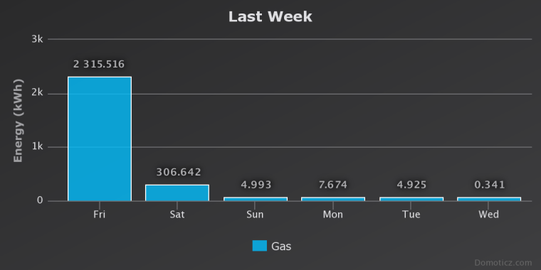
Here are some results from Domoticz. As you can see last Friday I had a spike. This was due to some of the same problems you are having. It has been running fine for the past several days since the last upgrade. I am using the same sketch that I posted.
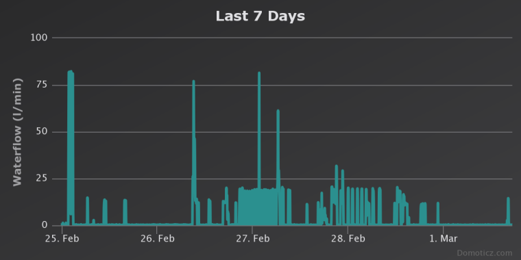
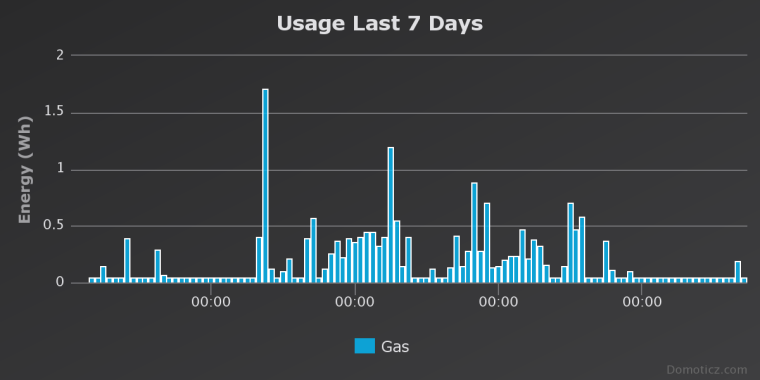
I haven't figure out how to remove the Energy (Wh) from the gas usage or the word Waterflow.
As for the fixing of the excessive pulse counts I also at times had he same problem as well. But make sure that your top and bottoms are correct first. If they are and your "next pulse at" number is just being bypassed and the pulse count keeps going up the solution was to reorder the code. Not sure how that helped but it did. I'm not the software guy in this project, my son is. But I know most of what is going on with it. If it continues to give you problems let me know, post your code and I'll get him to look at it.
The memory or GW numbers should be 0 but it not too critical if you are there to start it. It will recalculate the top and bottom values automatically after there has been 22 pulses within a send frequency. Just turn the stove or gas on so there is plenty of flow and download the sketch. It should either start reading the magnetic values and count pulses or start the time to find the top and bottom.
What do you mean by not understanding the pulse count? Are you sending any flow or volume data? Sorry if this jumps around but I'm in the process of doing something else and I'm distracted. Thanks for you patience.
-
@dpcr Are you using VAR1 for the pulse count? The reason why we didn't store the top and bottom values on the GW was if the GW went down for any reason we could still keep a pulse count. But it should still work if you have a connection to your GW and controller.
Here are some results from Domoticz. As you can see last Friday I had a spike. This was due to some of the same problems you are having. It has been running fine for the past several days since the last upgrade. I am using the same sketch that I posted.
I haven't figure out how to remove the Energy (Wh) from the gas usage or the word Waterflow.
As for the fixing of the excessive pulse counts I also at times had he same problem as well. But make sure that your top and bottoms are correct first. If they are and your "next pulse at" number is just being bypassed and the pulse count keeps going up the solution was to reorder the code. Not sure how that helped but it did. I'm not the software guy in this project, my son is. But I know most of what is going on with it. If it continues to give you problems let me know, post your code and I'll get him to look at it.
The memory or GW numbers should be 0 but it not too critical if you are there to start it. It will recalculate the top and bottom values automatically after there has been 22 pulses within a send frequency. Just turn the stove or gas on so there is plenty of flow and download the sketch. It should either start reading the magnetic values and count pulses or start the time to find the top and bottom.
What do you mean by not understanding the pulse count? Are you sending any flow or volume data? Sorry if this jumps around but I'm in the process of doing something else and I'm distracted. Thanks for you patience.
@dpcr Yes I use var1 for pulse count Var2 for Top and Var3 for bottom
if the retrieve of value from Gw/Controller is fine get the last Top and Bottom otherwise if retrieve fails after power cycle use locally hard coded, if the retrieve is 0 for TOP and BOTTOM starts auto-detect (gas must be flow) this happens on first run or if you want to manually starts a recalculation.
I think that the problem of spike... maybe related to a non triggering of top or bottom after magnetic field change due to temperature so pulse count going up until new top and bottom was recalculated and applied, there are a control over max pulse for cycle ?
for the count up probably there are a part of code time spending and the reading jump ?
on version V3.6304 of domoticz m3/h are displayed fine if you select gas type counter .... for flow maybe is still water flow reported.
for the pulse count i meaning looking at the code that you take a period then divide in division and trigger a pulse for every division is passed but i didn't understand if the metodology for counting pulse changed on the old and on the new code
here the code i have modified is a mix of old and new code you have posted plus the support to store on controller and a chek for not count more than todividers on rising or falling , i want to test if i can improve the count or not...
/*
 *
 *
 *
 *
 * Currently the autoDetectMaxMin in set to true which will find the TOP and BOTTOM of the wave, however if you want
 * to use it the gas must be flowing.
 */


#define MY_DEBUG
#define MY_RADIO_NRF24

#include <MySensors.h>
#include <Wire.h>                       //I2C Arduino Library

#define CHILD_ID 1                      //ID of the sensor child
#define SLEEP_MODE false                //prevent sensor from sleeping
#define address 0x1E                    //0011110b, I2C 7bit address of HMC5883

int TOP = 0;                            //highest magnetic field registered from meter (Ga)Initialize low if using AutoDetectMaxMin
int BOTTOM = 0;                         //lowest magnetic field registered from meter (Ga) Initialize high if using AutoDetectMaxMin
int NewTop=-9000;
int NewBottom=9000;
int tol = 50;
unsigned long SEND_FREQUENCY = 30000;   // Minimum time between send (in milliseconds). We don't want to spam the gateway.

bool metric = true;                     //sets units to Metric or English
bool autoDetectMaxMin = false;           //lets Arduino decide the values for TOP and BOTTOM
bool pcReceived = false;                //whether or not the gw has sent us a pulse count
bool rising = true;                     //whether or not a pulse has been triggered
bool inside = true;                     //whether the magnetic field is within TOP and BOTTOM limits
unsigned long pulsecount = 0;           //total number of pulses measured ever
unsigned long oldPulseCount = 0;        //old total
double vpp = 0.12;                      //Volume of gas per pulse
unsigned long lastSend = 0;             //time since last transmission - msec
double volume = 0;                      //Cumulative amount of gas measured
const int len = 3;                      //number of flow rate measurements to save
double flow [len];                      //array of previous gas flow rate measurements
double avgFlow = 0;                     //average of all elements in flow array
double oldAvgFlow = 0;                  //previous average flow
int divider = 1;                        //Current divider
int totDividers = 10;                    //Number of dividers
int increment = (TOP - BOTTOM) / totDividers;   //space b/w dividers
int newTop = -9000;                     //potential new Top
int newBottom = 9000;                   //potential new Bottom
int counter=0;

MyMessage flowMsg(CHILD_ID,V_FLOW);
MyMessage volumeMsg(CHILD_ID,V_VOLUME);
MyMessage lastCounterMsg(CHILD_ID,V_VAR1);
MyMessage lastTopMsg(CHILD_ID,V_VAR2);
MyMessage lastBottomMsg(CHILD_ID,V_VAR3);

void setup(){
  //Initialize Serial and I2C communications
  Serial.begin(115200);
  Wire.begin();

  // Fetch last known pulse count , TOP and BOTTOM value from gw
  request(CHILD_ID, V_VAR1);
  request(CHILD_ID, V_VAR2);
  request(CHILD_ID, V_VAR3);

  // Wait until timeout of 2 seconds for message from gw
  wait(2000, 2, V_VAR1);
  wait(2000, 2, V_VAR2);
  wait(2000, 2, V_VAR3);


  //Put the HMC5883 IC into the correct operating mode
  Wire.beginTransmission(address); //open communication with HMC5883
  Wire.write(0x02); //select mode register
  Wire.write(0x00); //continuous measurement mode
  Wire.endTransmission();

  int y = 0;
  int oldy = 0;

  //WARNING: MAKE SURE GAS IS RUNNING IF USING THIS OPTION!!!
  if(TOP==0 && BOTTOM==0){
  autoDetectMaxMin = true;
    //determine max and min magnetic field strength over a few minutes
    lastSend = millis();

    while(millis() - lastSend < 120000){
      y = readMag();
      if(y > TOP){
        TOP = y;                        //update TOP if new max has been detected
      }
      else if(y < BOTTOM){
        BOTTOM = y;                     //update BOTTOM if new min has been detected
      }
    }

    TOP -= tol;                         //nudge TOP and BOTTOM so that they have a chance of being triggered
    BOTTOM += tol;

    increment = (TOP - BOTTOM) / totDividers;    //recalculate increment to match new TOP and BOTTOM
    autoDetectMaxMin = false;           //finished determining TOP and BOTTOM

  Serial.println("Store on Controller TOP and BOTTOM found");
  send(lastTopMsg.set(TOP));
  send(lastBottomMsg.set(BOTTOM));

  }
  increment = (TOP - BOTTOM) / totDividers;    //recalculate increment to match new TOP and BOTTOM
  Serial.print("Increment = ");
  Serial.println(increment);

  oldy = readMag();
  y = readMag();
  while(abs(y - oldy) < increment / 2){ //wait until difference b/w y and oldy is greater than half an increment
    y = readMag();
  }
  rising = (y > oldy);
  Serial.println(rising ? "Magnetic field is rising" : "Magnetic field is falling");
}

void presentation()
{
    // Send the sketch version information to the gateway and Controller
    sendSketchInfo("Gas Meter", "0.4");

    // Register this device as Gas sensor
    present(CHILD_ID, S_GAS);
}

void loop(){
  if (!pcReceived) {
    //Last Pulsecount not yet received from controller, request it again
    request(CHILD_ID, V_VAR1);
    return;
  }
  //detecting magnetic pulses - Fractional Simple Method
  while(millis() - lastSend < SEND_FREQUENCY){
    int y = readMag();

  if(y >NewTop ){
        NewTop = y;                        //update TOP if new max has been detected
      }
      else if(y < NewBottom){
        NewBottom = y;                     //update BOTTOM if new min has been detected
      }

    if(inside && rising && y > BOTTOM + divider * increment && divider < totDividers+1){
      divider++;
      pulsecount++;
    }
    else if(inside && !rising && y < TOP - divider * increment &&  divider < totDividers+1){
      divider++;
      pulsecount++;
    }

    if(inside && (y > TOP || y < BOTTOM )){        //switch directions once TOP or BOTTOM divider has been reached
      inside = false;                 //keep this from happening multiple times once signal exceeds TOP or BOTTOM
      Serial.println("OUTSIDE");
    }
    else if(!inside && (y < TOP - increment / 2 && y > BOTTOM + increment / 2)){
      rising = !rising;
      divider = 1;
      inside = true;
      Serial.println("INSIDE");
    }
  }

counter += (pulsecount - oldPulseCount);      //update counter
    if(counter >= ((totDividers + 1) * 2)){
    if ( (abs(TOP-NewTop)) > tol || (abs(BOTTOM-NewBottom)) >tol){
      TOP=NewTop-tol;
      BOTTOM=NewBottom+tol;
      increment = (TOP - BOTTOM) / totDividers;    //recalculate increment to match new TOP and BOTTOM

      //Send Top and Bottom to gateway
      send(lastTopMsg.set(TOP));
      send(lastBottomMsg.set(BOTTOM));

      //reset newTop and newBottom
      newTop = -9000;
      newBottom = 9000;
      counter = 0;
      //display new bounds
      Serial.println("NEW BOUNDARIES SET:");
      Serial.print("Top = ");
      Serial.println(TOP);
      Serial.print("Bottom = ");
      Serial.println(BOTTOM);
      Serial.print("Increment = ");
      Serial.println(increment);
    }
  }


  //shift all flow array elements to the right by 1, ignore last element
  for(int idx = len - 1; idx > 0; idx--){
    flow[idx] = flow[idx - 1];
  }
  //calculate newest flow reading and store it as first element in flow array
  flow[0] = (double)(pulsecount - oldPulseCount) * (double)vpp * 60000.0 / (double)SEND_FREQUENCY;
  //display flow array state
  Serial.print("Flow Array State: [");
  for(int idx = 0; idx < len - 1; idx++){
    Serial.print(flow[idx]);
    Serial.print("|");
  }
  Serial.print(flow[len - 1]);
  Serial.println("]");
  //calculate average flow
  avgFlow = 0;                                //reset avgFlow
  for(int idx = 0; idx < len; idx++){         //calculate weighted sum of all elements in flow array
    avgFlow += (flow[idx] * (len - idx));
  }
  avgFlow /= (len * (len + 1) / 2);           //divide by triangle number of elements to get linear weighted average
  Serial.print("Average flow: ");             //display average flow
  Serial.println(avgFlow);
  //send flow message if avgFlow has changed
  if(avgFlow != oldAvgFlow){
    oldAvgFlow = avgFlow;
    send(flowMsg.set(avgFlow, 2));
  }

  //send updated cumulative pulse count and volume data, if necessary
  if(pulsecount != oldPulseCount){
    oldPulseCount = pulsecount;              //update old total

    //calculate volume
    volume = (double)oldPulseCount * (double)vpp / 1000.0;

    //send pulse count and volume data to gw
    send(lastCounterMsg.set(pulsecount));
    send(volumeMsg.set(volume, 3));
  }

  lastSend = millis();

}

void receive(const MyMessage &message)
{
  if (message.type==V_VAR1) {
    unsigned long gwPulseCount=message.getULong();
    pulsecount = gwPulseCount;
    oldPulseCount = pulsecount;
    Serial.print("Received last pulse count from gw:");
    Serial.println(pulsecount);
    pcReceived = true;
    lastSend = millis();
  }
  if (message.type==V_VAR2) {
    int gwStoredTOP=message.getInt();
    TOP = gwStoredTOP;
    Serial.print("Received stored TOP value from gw:");
    Serial.println(TOP);
  }
  if (message.type==V_VAR3) {
    int gwStoredBOTTOM=message.getInt();
    BOTTOM = gwStoredBOTTOM;
    Serial.print("Received stored BOTTOM value from gw:");
    Serial.println(BOTTOM);
  }
}
int readMag(){
  int x = 0, y = 0, z = 0;

  //Tell the HMC5883 where to begin reading data
  Wire.beginTransmission(address);
  Wire.write(0x03); //select register 3, X MSB register - was called Wire.send but the compiler had an error and said to rename to to Wire.write
  Wire.endTransmission();

  //Read data from each axis, 2 registers per axis
  Wire.requestFrom(address, 6);
  if(6<=Wire.available()){
    x = Wire.read()<<8; //X msb
    x |= Wire.read(); //X lsb
    z = Wire.read()<<8; //Z msb
    z |= Wire.read(); //Z lsb
    y = Wire.read()<<8; //Y msb
    y |= Wire.read(); //Y lsb
  }

  if(!autoDetectMaxMin){
    //show real-time magnetic field, pulse count, and pulse count total
    Serial.print("y: ");
    Serial.print(y);
    Serial.print(rising ? "  Rising, " : "  Falling, ");
    Serial.print("next pulse at: ");
    Serial.print(rising ? BOTTOM + divider * increment : TOP - divider * increment);
    Serial.print("  Current Number of Pulses: ");
    Serial.print(pulsecount - oldPulseCount);
    Serial.print("  Last Total Pulse Count Sent to GW: ");
    Serial.println(oldPulseCount);
  }
  else{
    //show real-time magnetic field, TOP, BOTTOM, and time left in auto-detect mode
    Serial.print("y: ");
    Serial.print(y);
    Serial.print("  TOP: ");
    Serial.print(TOP);
    Serial.print("  BOTTOM: ");
    Serial.print(BOTTOM);
    unsigned long remainingTime = 120000 + lastSend - millis();
    Serial.print("  Time remaining: ");
    Serial.print(remainingTime / 60000);
    Serial.print(":");
    remainingTime = (remainingTime % 60000) / 1000;
    if(remainingTime >= 10){
      Serial.println(remainingTime);
    }
    else{
      Serial.print("0");
      Serial.println(remainingTime);
    }

  }

  return y;

}
I have another little problem that after a while the node stop to work i don't know but on the serial stop to print data and no more message is sent to the gateway if i close and re-open the serial monitor the data readed by magnetometer is displayed again but no data is sent,
Can be related to radio issue ? or overbuffering serial ? do you have experienced similar problem? -
Yes, a major change in magnetic field readings while the sensor is powered down could result in a large number of pulses being triggered if Top and Bottom are drastically different than what the sensor has stored. It is best to reset Top and Bottom to 0 in that case, forcing Auto-Detect to run and get accurate values for Top and Bottom.
In future versions, I plan to add a feature that lets users choose to reset Top and Bottom from the Serial Monitor. If it's been a while since the sensor was last running or if operating conditions have changed (the sensor was relocated or something similar), users can use that feature to ensure that the program begins with proper values for Top and Bottom. I also plan on publishing two versions of the sketch: one that stores Top, Bottom, and Pulse Count in Fram, and one that stores those values on the controller.
As far as counting pulses goes, the old version and the new version aren't too different. They both divide the space between Top and Bottom into a number of divisions, and trigger pulses once a division is passed. The math they use to do it is slightly different. The old version calculates what number the magnetic field reading needs to rise/fall to and compares that to the most recent reading. The new version checks if the distance between the magnetic field reading that last triggered a pulse and the most recent reading is equal to or greater than the distance between divisions. The old version had problems when the magnetic field was switching from rising to falling (probably because I didn't continuously update Top and Bottom), but the new version feels more elegant. There's probably not much of a difference at this point, though.
I did have a problem where it seemed like the sensor wasn't printing anything to the serial monitor, but that was due to bad program flow that occasionally made it impossible to update lastSend. I've never had a problem that prevented the sensor from sending data to the Gateway.
-
Yes, a major change in magnetic field readings while the sensor is powered down could result in a large number of pulses being triggered if Top and Bottom are drastically different than what the sensor has stored. It is best to reset Top and Bottom to 0 in that case, forcing Auto-Detect to run and get accurate values for Top and Bottom.
In future versions, I plan to add a feature that lets users choose to reset Top and Bottom from the Serial Monitor. If it's been a while since the sensor was last running or if operating conditions have changed (the sensor was relocated or something similar), users can use that feature to ensure that the program begins with proper values for Top and Bottom. I also plan on publishing two versions of the sketch: one that stores Top, Bottom, and Pulse Count in Fram, and one that stores those values on the controller.
As far as counting pulses goes, the old version and the new version aren't too different. They both divide the space between Top and Bottom into a number of divisions, and trigger pulses once a division is passed. The math they use to do it is slightly different. The old version calculates what number the magnetic field reading needs to rise/fall to and compares that to the most recent reading. The new version checks if the distance between the magnetic field reading that last triggered a pulse and the most recent reading is equal to or greater than the distance between divisions. The old version had problems when the magnetic field was switching from rising to falling (probably because I didn't continuously update Top and Bottom), but the new version feels more elegant. There's probably not much of a difference at this point, though.
I did have a problem where it seemed like the sensor wasn't printing anything to the serial monitor, but that was due to bad program flow that occasionally made it impossible to update lastSend. I've never had a problem that prevented the sensor from sending data to the Gateway.
@dpcr New Sketch: This one is version 1.0 and works well with the hardware I'm using. It has an interactive start up menu in the serial monitor when starting which allows one to choose several options and var1 (variable used to store the pulse count on the controller) was removed and the pulse count is now stored in FRAM. It's been running for several months with no problem.
/* * Created by Sean Creel <creels15@gmail.com> * * Based on these projects by Henrik Ekblad and Korneliusz Jarzębski: * https://www.mysensors.org/build/pulse_water * https://github.com/jarzebski/Arduino-HMC5883L * * This program is free software; you can redistribute it and/or * modify it under the terms of the GNU General Public License * version 2 as published by the Free Software Foundation. * * DESCRIPTION: * Uses an I2C triple-axis magnetometer to measure a home's gas usage by * detecting small fluxuations in the local magnetic field caused by the * meter's bellows pumping in and out. Requires users to determine how * many cycles their meter completes per unit volume of gas flow. */ #define MY_DEBUG //enables debugging of MySensors messages #define MY_RADIO_NRF24 //lets MySensors know what radio you're using #include <MySensors.h> #include <Wire.h> //I2C communications library #include <Adafruit_FRAM_I2C.h> //Adafruit FRAM memory library #define CHILD_ID 1 //ID of the sensor child #define SLEEP_MODE false //prevent sensor from sleeping #define address 0x1E //0011110b, I2C 7bit address of HMC5883 magnetometer #define topAddr 4 //address of Top in FRAM #define bottomAddr 6 //address of Bottom in FRAM #define pulseAddr 0 //address of pulseCount in FRAM //USER-DEFINED CONSTANTS #define METRIC true //specifies the units of measurement #define AXIS "Y" //specifies which axes of the magnetometer to read from (multiple axes permitted, e.g. "ZX" or "YXZ") #define CYCLES_PER_CUFT 8 //cycles of the meter's bellows per cubic foot of gas (varies by meter model) #define NUM_DIVISIONS 10 //desired number of subdivisions per cycle. higher => more accuracy, lower => more tolerant of noise #define ERR 0.00221513400975639000 //used to fix discrepancies between theoretical and actual volume per pulse (vpp) #define LEN 3 //number of flow rate measurements to save for moving average. set to 1 if you want to send raw flow data instead #define SEND_FREQUENCY 30000 //Minimum time between messages to the GW (msec) #define TOL 50 //margin of error to account for noise coming from the sensor bool autoDetect = false; //true if the program is auto detecting Top and Bottom bool rising = true; //whether or not a pulse has been triggered bool safe = false; //whether or not it is safe to switch directions unsigned long pulseCount = 0; //total number of pulses measured ever unsigned long oldPulseCount = 0; //old total double vpp = ERR + (METRIC ? 28.3168 : 1.0) / (CYCLES_PER_CUFT * 2 * (NUM_DIVISIONS + 1));//Volume of gas per pulse ft^3/L unsigned long lastSend = 0; //time since last transmission - msec double flow [LEN]; //array of previous gas flow rate measurements double avgFlow = 0; //average of all elements in flow array double oldAvgFlow = 0; //previous average flow int b = 0; //magnetic field reading int oldB = 0; //previous magnetic field reading int top = 0; //highest magnetic field registered from meter (Ga)Initialize low if using autoDetectMaxMin int bottom = 0; //lowest magnetic field registered from meter (Ga) Initialize high if using autoDetectMaxMin int newTop = -9000; //potential new Top int newBottom = 9000; //potential new Bottom int increment = 0; //space b/w dividers int counter = 0; //used to count pulses over periods longer than SEND_FREQUENCY MyMessage flowMsg(CHILD_ID,V_FLOW); MyMessage volumeMsg(CHILD_ID,V_VOLUME); Adafruit_FRAM_I2C fram = Adafruit_FRAM_I2C(); void setup(){ //Initialize Serial, I2C, and FRAM communications Serial.begin(9600); Wire.begin(); fram.begin(); //Put the HMC5883 IC into the correct operating mode Wire.beginTransmission(address); //open communication with HMC5883 Wire.write(0x02); //select mode register Wire.write(0x00); //continuous measurement mode Wire.endTransmission(); //Prompt user for permission to clear all or part of FRAM Serial.println("Do you wish to clear all or part of long-term memory?"); Serial.println("Please enter a number 0-3:"); Serial.println("0: (default) Clear nothing"); Serial.println("1: Clear Top and Bottom"); Serial.println("2: Clear Pulse Count"); Serial.println("3: Clear Top, Bottom, and Pulse Count"); int choice = 0; lastSend = millis(); while(Serial.available() == 0 && millis() - lastSend < 30000); //wait 30s max for user input choice += Serial.parseInt(); if(choice == 1){ clearFram(4,8); Serial.println("Top and Bottom values reset"); } else if(choice == 2){ clearFram(0,4); Serial.println("Pulse Count reset"); } else if(choice == 3){ clearFram(0,8); Serial.println("All stored values reset"); } //get pulseCount from FRAM pulseCount = readUL(pulseAddr); oldPulseCount = pulseCount; //get Top and Bottom from FRAM newTop = readInt(topAddr); newBottom = readInt(bottomAddr); updateBounds(); //WARNING: MAKE SURE GAS IS RUNNING ON FIRST RUNNING OF THIS PROGRAM!!! if(top == 0 && bottom == 0){ autoDetect = true; newTop = -9000; newBottom = 9000; //determine max and min magnetic field strength over a few minutes Serial.println("FRAM has been cleared. Auto-detecting max and min magnetic field reading."); Serial.println("WARNING: MAKE SURE GAS IS RUNNING!!"); lastSend = millis(); while(millis() - lastSend < 120000){ readMag(); detectMaxMin(); //display details Serial.print("Magnetic Field: "); Serial.print(b); Serial.print(" Top: "); Serial.print(newTop); Serial.print(" Bottom: "); Serial.print(newBottom); unsigned long remainingTime = 120000 + lastSend - millis(); Serial.print(" Time remaining: "); Serial.print(remainingTime / 60000); Serial.print(":"); remainingTime = (remainingTime % 60000) / 1000; if(remainingTime >= 10){ Serial.println(remainingTime); } else{ Serial.print("0"); Serial.println(remainingTime); } } updateBounds(); autoDetect = false; } readMag(); oldB = b; while(abs(b - oldB) < increment / 2){ //wait until difference b/w b and oldB is greater than half an increment readMag(); } rising = (b > oldB); Serial.println(rising ? "Magnetic field is rising" : "Magnetic field is falling"); Serial.print("Volume Per Pulse = "); Serial.print(vpp,16); Serial.println(METRIC ? " L/pulse" : "cuft/pulse"); lastSend = millis(); } void presentation() { // Send the sketch version information to the gateway and Controller sendSketchInfo("Gas Meter", "1.0 (4/4/17)"); // Register this device as Gas sensor present(CHILD_ID, S_GAS); } void loop(){ //detecting magnetic pulses - variable boundary method while(millis() - lastSend < SEND_FREQUENCY){ //check if the signal has significantly increased/decreased if(abs(oldB - b) > increment){ pulseCount ++; //increment or decrement oldB by one increment based on direction oldB += rising ? increment : -1 * increment; safe = false; //reset safe now that oldB has updated } //check if the signal has recently switched directions else if(safe){ //first make sure b has moved a significant distance from oldB if((rising && b <= oldB) || (!rising && b >= oldB)){ pulseCount ++; //add one extra pulse rising = !rising; //update direction safe = false; } } //take another reading readMag(); //check if b has moved a significant distance from oldB if(abs(b - oldB) > TOL / 2){ safe = true; } //update newTop and newBottom detectMaxMin(); } //shift all flow array elements to the right by 1, ignore last element for(int idx = LEN - 1; idx > 0; idx--){ flow[idx] = flow[idx - 1]; } //calculate newest flow reading and store it as first element in flow array flow[0] = (double)(pulseCount - oldPulseCount) * vpp * 60000.0 / (double)SEND_FREQUENCY; //display flow array state Serial.print("Flow Array State: ["); for(int idx = 0; idx < LEN - 1; idx++){ Serial.print(flow[idx]); Serial.print("|"); } Serial.print(flow[LEN - 1]); Serial.println("]"); //calculate average flow avgFlow = 0; //reset avgFlow for(int idx = 0; idx < LEN; idx++){ //calculate weighted sum of all elements in flow array avgFlow += (flow[idx] * (LEN - idx)); } avgFlow /= (LEN * (LEN + 1) / 2); //divide by triangle number of elements to get linear weighted average Serial.print("Average flow: "); //display average flow Serial.println(avgFlow); //send flow message if avgFlow has changed if(avgFlow != oldAvgFlow){ oldAvgFlow = avgFlow; send(flowMsg.set(avgFlow, 2)); } //send updated volume data if necessary if(pulseCount != oldPulseCount){ //send volume data to gw send(volumeMsg.set(((double)pulseCount * vpp / (METRIC ? 1000.0 : 1)), 3)); //store updated pulse count total in FRAM writeUL(pulseAddr,pulseCount); counter += (pulseCount - oldPulseCount); //update counter if(counter >= ((NUM_DIVISIONS + 1) * 2)){ updateBounds(); //update bounds if at least 1 cycle has been read counter = 0; //reset counter } oldPulseCount = pulseCount; //update old pulse count total } lastSend = millis(); } void updateBounds(){ if((top != newTop) && (bottom != newBottom)){ //check if anything has actually changed //lock in Top and Bottom top = newTop; bottom = newBottom; //recalculate increment to match new top and bottom increment = (top - bottom - (2 * TOL)) / NUM_DIVISIONS; //store updated Top and Bottom in FRAM writeInt(topAddr,top); writeInt(bottomAddr,bottom); //reset newTop and newBottom newTop = -9000; newBottom = 9000; //display new bounds Serial.println("NEW BOUNDARIES SET:"); Serial.print("Top = "); Serial.println(top); Serial.print("Bottom = "); Serial.println(bottom); Serial.print("Increment = "); Serial.println(increment); } } void detectMaxMin(){ if(b > newTop){ newTop = b; //update newTop if new max has been detected } else if(b < newBottom){ newBottom = b; //update newBottom if new min has been detected } } void writeInt(int addr, int val){ //write an int value to FRAM byte b = highByte(val); fram.write8(addr,b); b = lowByte(val); fram.write8(addr + 1,b); } void writeUL(int addr, unsigned long val){ //write an unsigned long falue to FRAM byte b = B00000000; for(int idx = 0; idx < sizeof(unsigned long); idx++){ b = val >> 8 * (sizeof(unsigned long) - 1 - idx); fram.write8(addr + idx,b); } } unsigned long readUL(int addr){ //read an unsigned long value from FRAM unsigned long result = 0; for(int idx = 0; idx < sizeof(unsigned long); idx++){ result = result << 8; result += (unsigned long)fram.read8(addr + idx); } return result; } int readInt(int addr){ //read an int value from FRAM int result = 0; result += (int)fram.read8(addr); result = result << 8; result += (int)fram.read8(addr + 1); return result; } void clearFram(int first, int last){ for(int addr = first; addr < last; addr++){ fram.write8(addr,byte(0)); } } void readMag(){ static int x = 0, y = 0, z = 0; //Tell the HMC5883 where to begin reading data Wire.beginTransmission(address); Wire.write(0x03); //select register 3, X MSB register - was called Wire.send but the compiler had an error and said to rename to to Wire.write Wire.endTransmission(); //Read data from each axis, 2 registers per axis Wire.requestFrom(address, 6); if(6<=Wire.available()){ x = Wire.read()<<8; //X msb x |= Wire.read(); //X lsb z = Wire.read()<<8; //Z msb z |= Wire.read(); //Z lsb y = Wire.read()<<8; //Y msb y |= Wire.read(); //Y lsb } if(String(AXIS).equalsIgnoreCase("X")){ b = x; } else if(String(AXIS).equalsIgnoreCase("Y")){ b = y; } else if(String(AXIS).equalsIgnoreCase("Z")){ b = z; } else if(String(AXIS).equalsIgnoreCase("XY") || String(AXIS).equalsIgnoreCase("YX")){ b = x * x + y * y; } else if(String(AXIS).equalsIgnoreCase("XZ") || String(AXIS).equalsIgnoreCase("ZX")){ b = x * x + z * z; } else if(String(AXIS).equalsIgnoreCase("YZ") || String(AXIS).equalsIgnoreCase("ZY")){ b = y * y + z * z; } else if(String(AXIS).equalsIgnoreCase("XYZ") || String(AXIS).equalsIgnoreCase("XZY") || String(AXIS).equalsIgnoreCase("YXZ") || String(AXIS).equalsIgnoreCase("YZX") || String(AXIS).equalsIgnoreCase("ZYX") || String(AXIS).equalsIgnoreCase("ZXY")){ b = x * x + y * y + z * z; } else { b = 0; } if(!autoDetect){ //show real-time magnetic field, pulse count, and pulse count total Serial.print("Magnetic Field: "); Serial.print(b); Serial.print(rising ? " Rising, " : " Falling, "); Serial.print("next pulse at: "); Serial.print(rising ? oldB + increment : oldB - increment); Serial.print(" Current Number of Pulses: "); Serial.print(pulseCount - oldPulseCount); Serial.print(" Last Total Pulse Count Sent to GW: "); Serial.println(oldPulseCount); } }``` -
@dpcr New Sketch: This one is version 1.0 and works well with the hardware I'm using. It has an interactive start up menu in the serial monitor when starting which allows one to choose several options and var1 (variable used to store the pulse count on the controller) was removed and the pulse count is now stored in FRAM. It's been running for several months with no problem.
/* * Created by Sean Creel <creels15@gmail.com> * * Based on these projects by Henrik Ekblad and Korneliusz Jarzębski: * https://www.mysensors.org/build/pulse_water * https://github.com/jarzebski/Arduino-HMC5883L * * This program is free software; you can redistribute it and/or * modify it under the terms of the GNU General Public License * version 2 as published by the Free Software Foundation. * * DESCRIPTION: * Uses an I2C triple-axis magnetometer to measure a home's gas usage by * detecting small fluxuations in the local magnetic field caused by the * meter's bellows pumping in and out. Requires users to determine how * many cycles their meter completes per unit volume of gas flow. */ #define MY_DEBUG //enables debugging of MySensors messages #define MY_RADIO_NRF24 //lets MySensors know what radio you're using #include <MySensors.h> #include <Wire.h> //I2C communications library #include <Adafruit_FRAM_I2C.h> //Adafruit FRAM memory library #define CHILD_ID 1 //ID of the sensor child #define SLEEP_MODE false //prevent sensor from sleeping #define address 0x1E //0011110b, I2C 7bit address of HMC5883 magnetometer #define topAddr 4 //address of Top in FRAM #define bottomAddr 6 //address of Bottom in FRAM #define pulseAddr 0 //address of pulseCount in FRAM //USER-DEFINED CONSTANTS #define METRIC true //specifies the units of measurement #define AXIS "Y" //specifies which axes of the magnetometer to read from (multiple axes permitted, e.g. "ZX" or "YXZ") #define CYCLES_PER_CUFT 8 //cycles of the meter's bellows per cubic foot of gas (varies by meter model) #define NUM_DIVISIONS 10 //desired number of subdivisions per cycle. higher => more accuracy, lower => more tolerant of noise #define ERR 0.00221513400975639000 //used to fix discrepancies between theoretical and actual volume per pulse (vpp) #define LEN 3 //number of flow rate measurements to save for moving average. set to 1 if you want to send raw flow data instead #define SEND_FREQUENCY 30000 //Minimum time between messages to the GW (msec) #define TOL 50 //margin of error to account for noise coming from the sensor bool autoDetect = false; //true if the program is auto detecting Top and Bottom bool rising = true; //whether or not a pulse has been triggered bool safe = false; //whether or not it is safe to switch directions unsigned long pulseCount = 0; //total number of pulses measured ever unsigned long oldPulseCount = 0; //old total double vpp = ERR + (METRIC ? 28.3168 : 1.0) / (CYCLES_PER_CUFT * 2 * (NUM_DIVISIONS + 1));//Volume of gas per pulse ft^3/L unsigned long lastSend = 0; //time since last transmission - msec double flow [LEN]; //array of previous gas flow rate measurements double avgFlow = 0; //average of all elements in flow array double oldAvgFlow = 0; //previous average flow int b = 0; //magnetic field reading int oldB = 0; //previous magnetic field reading int top = 0; //highest magnetic field registered from meter (Ga)Initialize low if using autoDetectMaxMin int bottom = 0; //lowest magnetic field registered from meter (Ga) Initialize high if using autoDetectMaxMin int newTop = -9000; //potential new Top int newBottom = 9000; //potential new Bottom int increment = 0; //space b/w dividers int counter = 0; //used to count pulses over periods longer than SEND_FREQUENCY MyMessage flowMsg(CHILD_ID,V_FLOW); MyMessage volumeMsg(CHILD_ID,V_VOLUME); Adafruit_FRAM_I2C fram = Adafruit_FRAM_I2C(); void setup(){ //Initialize Serial, I2C, and FRAM communications Serial.begin(9600); Wire.begin(); fram.begin(); //Put the HMC5883 IC into the correct operating mode Wire.beginTransmission(address); //open communication with HMC5883 Wire.write(0x02); //select mode register Wire.write(0x00); //continuous measurement mode Wire.endTransmission(); //Prompt user for permission to clear all or part of FRAM Serial.println("Do you wish to clear all or part of long-term memory?"); Serial.println("Please enter a number 0-3:"); Serial.println("0: (default) Clear nothing"); Serial.println("1: Clear Top and Bottom"); Serial.println("2: Clear Pulse Count"); Serial.println("3: Clear Top, Bottom, and Pulse Count"); int choice = 0; lastSend = millis(); while(Serial.available() == 0 && millis() - lastSend < 30000); //wait 30s max for user input choice += Serial.parseInt(); if(choice == 1){ clearFram(4,8); Serial.println("Top and Bottom values reset"); } else if(choice == 2){ clearFram(0,4); Serial.println("Pulse Count reset"); } else if(choice == 3){ clearFram(0,8); Serial.println("All stored values reset"); } //get pulseCount from FRAM pulseCount = readUL(pulseAddr); oldPulseCount = pulseCount; //get Top and Bottom from FRAM newTop = readInt(topAddr); newBottom = readInt(bottomAddr); updateBounds(); //WARNING: MAKE SURE GAS IS RUNNING ON FIRST RUNNING OF THIS PROGRAM!!! if(top == 0 && bottom == 0){ autoDetect = true; newTop = -9000; newBottom = 9000; //determine max and min magnetic field strength over a few minutes Serial.println("FRAM has been cleared. Auto-detecting max and min magnetic field reading."); Serial.println("WARNING: MAKE SURE GAS IS RUNNING!!"); lastSend = millis(); while(millis() - lastSend < 120000){ readMag(); detectMaxMin(); //display details Serial.print("Magnetic Field: "); Serial.print(b); Serial.print(" Top: "); Serial.print(newTop); Serial.print(" Bottom: "); Serial.print(newBottom); unsigned long remainingTime = 120000 + lastSend - millis(); Serial.print(" Time remaining: "); Serial.print(remainingTime / 60000); Serial.print(":"); remainingTime = (remainingTime % 60000) / 1000; if(remainingTime >= 10){ Serial.println(remainingTime); } else{ Serial.print("0"); Serial.println(remainingTime); } } updateBounds(); autoDetect = false; } readMag(); oldB = b; while(abs(b - oldB) < increment / 2){ //wait until difference b/w b and oldB is greater than half an increment readMag(); } rising = (b > oldB); Serial.println(rising ? "Magnetic field is rising" : "Magnetic field is falling"); Serial.print("Volume Per Pulse = "); Serial.print(vpp,16); Serial.println(METRIC ? " L/pulse" : "cuft/pulse"); lastSend = millis(); } void presentation() { // Send the sketch version information to the gateway and Controller sendSketchInfo("Gas Meter", "1.0 (4/4/17)"); // Register this device as Gas sensor present(CHILD_ID, S_GAS); } void loop(){ //detecting magnetic pulses - variable boundary method while(millis() - lastSend < SEND_FREQUENCY){ //check if the signal has significantly increased/decreased if(abs(oldB - b) > increment){ pulseCount ++; //increment or decrement oldB by one increment based on direction oldB += rising ? increment : -1 * increment; safe = false; //reset safe now that oldB has updated } //check if the signal has recently switched directions else if(safe){ //first make sure b has moved a significant distance from oldB if((rising && b <= oldB) || (!rising && b >= oldB)){ pulseCount ++; //add one extra pulse rising = !rising; //update direction safe = false; } } //take another reading readMag(); //check if b has moved a significant distance from oldB if(abs(b - oldB) > TOL / 2){ safe = true; } //update newTop and newBottom detectMaxMin(); } //shift all flow array elements to the right by 1, ignore last element for(int idx = LEN - 1; idx > 0; idx--){ flow[idx] = flow[idx - 1]; } //calculate newest flow reading and store it as first element in flow array flow[0] = (double)(pulseCount - oldPulseCount) * vpp * 60000.0 / (double)SEND_FREQUENCY; //display flow array state Serial.print("Flow Array State: ["); for(int idx = 0; idx < LEN - 1; idx++){ Serial.print(flow[idx]); Serial.print("|"); } Serial.print(flow[LEN - 1]); Serial.println("]"); //calculate average flow avgFlow = 0; //reset avgFlow for(int idx = 0; idx < LEN; idx++){ //calculate weighted sum of all elements in flow array avgFlow += (flow[idx] * (LEN - idx)); } avgFlow /= (LEN * (LEN + 1) / 2); //divide by triangle number of elements to get linear weighted average Serial.print("Average flow: "); //display average flow Serial.println(avgFlow); //send flow message if avgFlow has changed if(avgFlow != oldAvgFlow){ oldAvgFlow = avgFlow; send(flowMsg.set(avgFlow, 2)); } //send updated volume data if necessary if(pulseCount != oldPulseCount){ //send volume data to gw send(volumeMsg.set(((double)pulseCount * vpp / (METRIC ? 1000.0 : 1)), 3)); //store updated pulse count total in FRAM writeUL(pulseAddr,pulseCount); counter += (pulseCount - oldPulseCount); //update counter if(counter >= ((NUM_DIVISIONS + 1) * 2)){ updateBounds(); //update bounds if at least 1 cycle has been read counter = 0; //reset counter } oldPulseCount = pulseCount; //update old pulse count total } lastSend = millis(); } void updateBounds(){ if((top != newTop) && (bottom != newBottom)){ //check if anything has actually changed //lock in Top and Bottom top = newTop; bottom = newBottom; //recalculate increment to match new top and bottom increment = (top - bottom - (2 * TOL)) / NUM_DIVISIONS; //store updated Top and Bottom in FRAM writeInt(topAddr,top); writeInt(bottomAddr,bottom); //reset newTop and newBottom newTop = -9000; newBottom = 9000; //display new bounds Serial.println("NEW BOUNDARIES SET:"); Serial.print("Top = "); Serial.println(top); Serial.print("Bottom = "); Serial.println(bottom); Serial.print("Increment = "); Serial.println(increment); } } void detectMaxMin(){ if(b > newTop){ newTop = b; //update newTop if new max has been detected } else if(b < newBottom){ newBottom = b; //update newBottom if new min has been detected } } void writeInt(int addr, int val){ //write an int value to FRAM byte b = highByte(val); fram.write8(addr,b); b = lowByte(val); fram.write8(addr + 1,b); } void writeUL(int addr, unsigned long val){ //write an unsigned long falue to FRAM byte b = B00000000; for(int idx = 0; idx < sizeof(unsigned long); idx++){ b = val >> 8 * (sizeof(unsigned long) - 1 - idx); fram.write8(addr + idx,b); } } unsigned long readUL(int addr){ //read an unsigned long value from FRAM unsigned long result = 0; for(int idx = 0; idx < sizeof(unsigned long); idx++){ result = result << 8; result += (unsigned long)fram.read8(addr + idx); } return result; } int readInt(int addr){ //read an int value from FRAM int result = 0; result += (int)fram.read8(addr); result = result << 8; result += (int)fram.read8(addr + 1); return result; } void clearFram(int first, int last){ for(int addr = first; addr < last; addr++){ fram.write8(addr,byte(0)); } } void readMag(){ static int x = 0, y = 0, z = 0; //Tell the HMC5883 where to begin reading data Wire.beginTransmission(address); Wire.write(0x03); //select register 3, X MSB register - was called Wire.send but the compiler had an error and said to rename to to Wire.write Wire.endTransmission(); //Read data from each axis, 2 registers per axis Wire.requestFrom(address, 6); if(6<=Wire.available()){ x = Wire.read()<<8; //X msb x |= Wire.read(); //X lsb z = Wire.read()<<8; //Z msb z |= Wire.read(); //Z lsb y = Wire.read()<<8; //Y msb y |= Wire.read(); //Y lsb } if(String(AXIS).equalsIgnoreCase("X")){ b = x; } else if(String(AXIS).equalsIgnoreCase("Y")){ b = y; } else if(String(AXIS).equalsIgnoreCase("Z")){ b = z; } else if(String(AXIS).equalsIgnoreCase("XY") || String(AXIS).equalsIgnoreCase("YX")){ b = x * x + y * y; } else if(String(AXIS).equalsIgnoreCase("XZ") || String(AXIS).equalsIgnoreCase("ZX")){ b = x * x + z * z; } else if(String(AXIS).equalsIgnoreCase("YZ") || String(AXIS).equalsIgnoreCase("ZY")){ b = y * y + z * z; } else if(String(AXIS).equalsIgnoreCase("XYZ") || String(AXIS).equalsIgnoreCase("XZY") || String(AXIS).equalsIgnoreCase("YXZ") || String(AXIS).equalsIgnoreCase("YZX") || String(AXIS).equalsIgnoreCase("ZYX") || String(AXIS).equalsIgnoreCase("ZXY")){ b = x * x + y * y + z * z; } else { b = 0; } if(!autoDetect){ //show real-time magnetic field, pulse count, and pulse count total Serial.print("Magnetic Field: "); Serial.print(b); Serial.print(rising ? " Rising, " : " Falling, "); Serial.print("next pulse at: "); Serial.print(rising ? oldB + increment : oldB - increment); Serial.print(" Current Number of Pulses: "); Serial.print(pulseCount - oldPulseCount); Serial.print(" Last Total Pulse Count Sent to GW: "); Serial.println(oldPulseCount); } }```@dpcr Nice adjustment of your Original code. Based on your Original version I have started coding as well as I like the simpleness of just adding a sensor to the meter without taking care of the direct position.
My current code can be found at github via the following link:https://github.com/rspaargaren/Read_Gasmeter/blob/Workinprogress/Read_Gasmeter.ino
Basic differences are:
- I have removed the fram reference but this could be added again if you use it.
- I have added a different setup sequence for fixing the top and bottom. In my case it waits until four changes in direction have occured. So no direct gas flow have to flow after a restart.
- The number of pulses between a change in direction is fixed independent of a change in top or bottom. So in my case every half a cycle will give ten pulses and a full cycle 20 pulses.
- The results are submitted to the gateway after a intervall but also after half a cycle.
- The top and bottom is checked after each cycle. So in case of major difference the interval is changed.
- During normal run, the reading of the y value is executed within the loop. So basically the arduino has time to do some other stuff as well in between the readings.
The code is currently working but requires some clean up. Also I would like to make an option to store the values at the gateway and maybe change the hardware to an ESP version so I can have multiple ways of output. Like MQTT.
This is the current output in Grafana: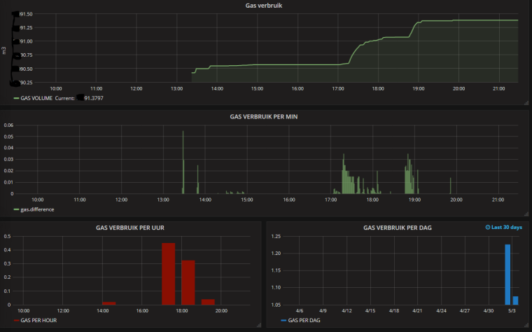
-
@dpcr Nice adjustment of your Original code. Based on your Original version I have started coding as well as I like the simpleness of just adding a sensor to the meter without taking care of the direct position.
My current code can be found at github via the following link:https://github.com/rspaargaren/Read_Gasmeter/blob/Workinprogress/Read_Gasmeter.ino
Basic differences are:
- I have removed the fram reference but this could be added again if you use it.
- I have added a different setup sequence for fixing the top and bottom. In my case it waits until four changes in direction have occured. So no direct gas flow have to flow after a restart.
- The number of pulses between a change in direction is fixed independent of a change in top or bottom. So in my case every half a cycle will give ten pulses and a full cycle 20 pulses.
- The results are submitted to the gateway after a intervall but also after half a cycle.
- The top and bottom is checked after each cycle. So in case of major difference the interval is changed.
- During normal run, the reading of the y value is executed within the loop. So basically the arduino has time to do some other stuff as well in between the readings.
The code is currently working but requires some clean up. Also I would like to make an option to store the values at the gateway and maybe change the hardware to an ESP version so I can have multiple ways of output. Like MQTT.
This is the current output in Grafana: -
@dynamite I just scanned quickly over your code. So there is no need to store the top and bottom values? What do you do on a power failure? I look forward to hearing from you more.
Do you have any pics of your hardware?
@dpcr At the moment I do not store the top and bottom value permanently. In case of a power failure I will "loose" to the max two rounds of the wheel on pulses as it uses that to calibrate the top and bottom. That could be reduced to potentially only one cycle. Which is in my case 0,01m3 to 0,02 m3 of gas indication.
After the power failure the process starts in the calibration loop which is ended only after the required cycles have registered. So this could last 30 sec in case you are having a shower but can last a week if you are away...I will post a picture of my setup later.
Now I am thinking of it. If you do not care about the accuracy that much you do not need the top and bottom values at all. You just need to detect the rice and fall. That still gives you double the accuracy than a reed contact or Hall effect. The sketch for that will be very simple and after power down you can continue most probably without loss of pulses.
-
@dpcr At the moment I do not store the top and bottom value permanently. In case of a power failure I will "loose" to the max two rounds of the wheel on pulses as it uses that to calibrate the top and bottom. That could be reduced to potentially only one cycle. Which is in my case 0,01m3 to 0,02 m3 of gas indication.
After the power failure the process starts in the calibration loop which is ended only after the required cycles have registered. So this could last 30 sec in case you are having a shower but can last a week if you are away...I will post a picture of my setup later.
Now I am thinking of it. If you do not care about the accuracy that much you do not need the top and bottom values at all. You just need to detect the rice and fall. That still gives you double the accuracy than a reed contact or Hall effect. The sketch for that will be very simple and after power down you can continue most probably without loss of pulses.
@dynamite Great idea (top and bottom). We were kicking that around when we made this but wanted to err on the side of missing little to no gas flow. We have a pilot light on our water heater the draws around .1 lpm and I want to capture that as well.
I agree with you on the accuracy of using a magnetometer over a hall or reed switch, but they (hall or reed) are much easy to program. Too bad there isn't a library for converting a sine wave to pulses, don't forget that sometimes it doesn't look like a sine wave.
I'm curious to see how you mounted your magnetometer to your gas meter, mine seems a little too bulky and obtrusive. I did manage to buy another magnetometer and dip it in some stuff called PlastiDip. Its used for insulating the handles of tools. I just haven't switched them out yet to see how well it works.
-
@dynamite Great idea (top and bottom). We were kicking that around when we made this but wanted to err on the side of missing little to no gas flow. We have a pilot light on our water heater the draws around .1 lpm and I want to capture that as well.
I agree with you on the accuracy of using a magnetometer over a hall or reed switch, but they (hall or reed) are much easy to program. Too bad there isn't a library for converting a sine wave to pulses, don't forget that sometimes it doesn't look like a sine wave.
I'm curious to see how you mounted your magnetometer to your gas meter, mine seems a little too bulky and obtrusive. I did manage to buy another magnetometer and dip it in some stuff called PlastiDip. Its used for insulating the handles of tools. I just haven't switched them out yet to see how well it works.
@dpcr Hi the reason that it is sometimes not a sine wave is the reason why I used a fixed number of pulses between the top of bottom. So in case the flow is very low as for your pilot light it will detect every puls. In case you have a very heavy flow pulses can be skipped as long as the change is detected then in my case 10 pulses are submitted to the gate way. I was detecting in your original sketch sometimes extra pulses were submitted as the sine was little bit rising or the opposite dropping.
The code for just detecting rise and fall can be quite straigh foreward. I might make a second version like that...just for the record.
My Setup is quite straight forward. A small box with the arduino pro mini and radio. A cable to the magneto sensor. In my case water proof is not required. I have applied the sensor by Velcro strap so I can remove the setup in case of "Maintenance".
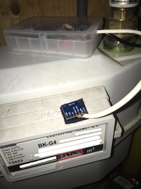
-
@dpcr Hi the reason that it is sometimes not a sine wave is the reason why I used a fixed number of pulses between the top of bottom. So in case the flow is very low as for your pilot light it will detect every puls. In case you have a very heavy flow pulses can be skipped as long as the change is detected then in my case 10 pulses are submitted to the gate way. I was detecting in your original sketch sometimes extra pulses were submitted as the sine was little bit rising or the opposite dropping.
The code for just detecting rise and fall can be quite straigh foreward. I might make a second version like that...just for the record.
My Setup is quite straight forward. A small box with the arduino pro mini and radio. A cable to the magneto sensor. In my case water proof is not required. I have applied the sensor by Velcro strap so I can remove the setup in case of "Maintenance".
@dynamite I seem to have the same meter; the BK-G4 :
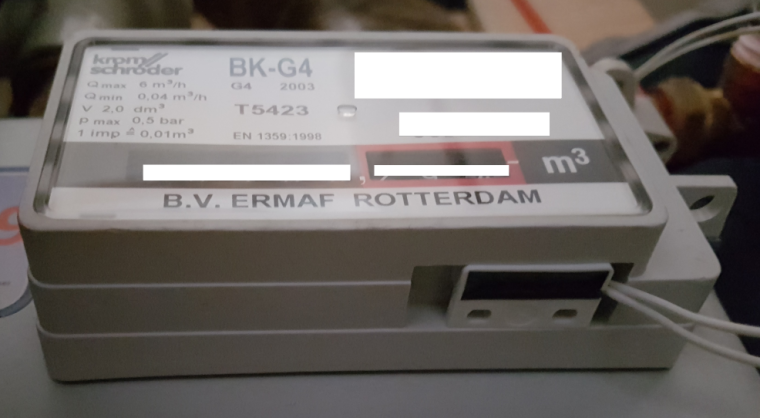
The 'official' place to stick a reed sensor is a hole on the bottom-right, as you can see in the picture.
I had a spare reed switch from a Senseo coffee machine, which perfectly fits the hole and works perfect!Maybe if you stick the compass sensor here, the signal will be more consistent/repeatable, as it should be more or less the same with each revolution.
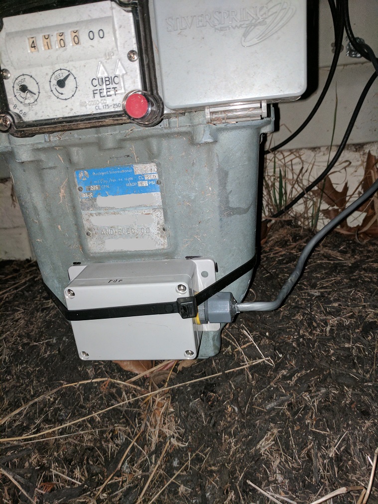
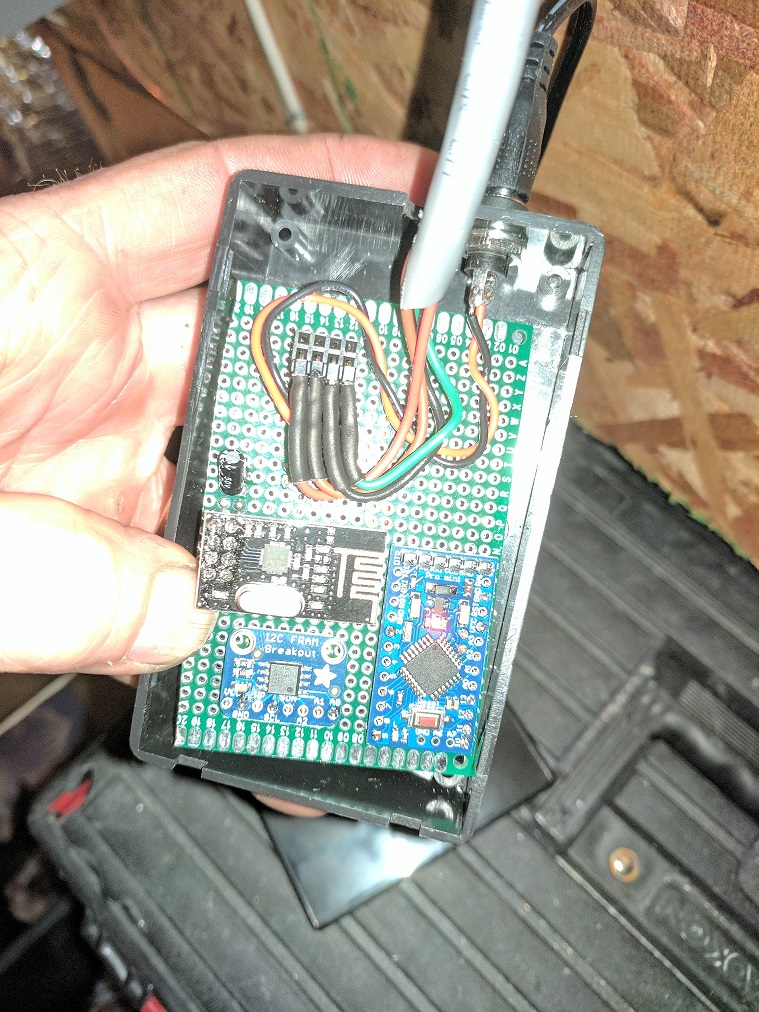
Hello! It looks like you're interested in this conversation, but you don't have an account yet.
Getting fed up of having to scroll through the same posts each visit? When you register for an account, you'll always come back to exactly where you were before, and choose to be notified of new replies (either via email, or push notification). You'll also be able to save bookmarks and upvote posts to show your appreciation to other community members.
With your input, this post could be even better 💗
Register Login