Another simple (No SMT) relay actuator
-
Feeling a bit confused how do you know that a bootloader uses the internal clock?
Because I used another bootloader after installing your card, I did not get the Atmega circuit to run. But if I used this bootloader, I started the Atmega circuit and everything worked.But what makes the internal clock in used?
I use a UNO when I'm burning bootloader and do not know if you can change fuses and clock option. -
Feeling a bit confused how do you know that a bootloader uses the internal clock?
Because I used another bootloader after installing your card, I did not get the Atmega circuit to run. But if I used this bootloader, I started the Atmega circuit and everything worked.But what makes the internal clock in used?
I use a UNO when I'm burning bootloader and do not know if you can change fuses and clock option.@MLs I think i lost you there, if there is no external osc how would it work? it is clear (at list to me) that its using the internal clock. Maybe you mean the f_cpu parameter? it is in the board text file.
I also use a nano to burn the bootloader, you can set the fuses as you wish in the boards page exactly as the link you gave is describing.
If you dont care of OTA you can use any other bootloader (like optiboot), i did it as well with this board.
I want to help you more but i need more info and pictures of your exact setup and files, can you share it?
Also some times your atmega328p-pu comes with 16Mhz bootloader pre-installed so you do need to set it up with 16Mhz osc for the first 8Mhz bootloader burn, after that you can remove it.
-
@MLs I think i lost you there, if there is no external osc how would it work? it is clear (at list to me) that its using the internal clock. Maybe you mean the f_cpu parameter? it is in the board text file.
I also use a nano to burn the bootloader, you can set the fuses as you wish in the boards page exactly as the link you gave is describing.
If you dont care of OTA you can use any other bootloader (like optiboot), i did it as well with this board.
I want to help you more but i need more info and pictures of your exact setup and files, can you share it?
Also some times your atmega328p-pu comes with 16Mhz bootloader pre-installed so you do need to set it up with 16Mhz osc for the first 8Mhz bootloader burn, after that you can remove it.
@dpressle
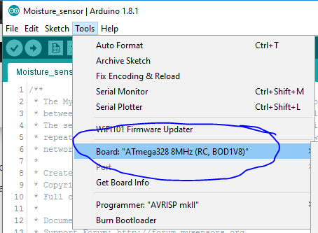
Ok first, I have to say that I have no problem getting your project to work. It connects directly to HA. What I get a little confused about is that according to the link I linked to it says.Be sure to select "ATmega328 on a breadboard (8 MHz internal clock)" when burning the bootloader.(If you select the wrong item and configure the microcontroller to use an external clock, it won't work unless you connect one.)
And as I interpret your post, you can take whatever bootloader you want (8 MHz).
And if I understand you right now, all settings iis n the board.txt file?//Mattias
-
@dpressle
Ok first, I have to say that I have no problem getting your project to work. It connects directly to HA. What I get a little confused about is that according to the link I linked to it says.Be sure to select "ATmega328 on a breadboard (8 MHz internal clock)" when burning the bootloader.(If you select the wrong item and configure the microcontroller to use an external clock, it won't work unless you connect one.)
And as I interpret your post, you can take whatever bootloader you want (8 MHz).
And if I understand you right now, all settings iis n the board.txt file?//Mattias
@MLs When i said "what ever bootloader you want" i meant MYS OTA bootloader or optiboot or breadboard bootloader etc.
They all have 8 Mhz version.In any way this is my boards.txt settings if it helps:
MYSBL13.name=ATmega328 8MHz (RC, BOD1V8)MYSBL13.upload.maximum_size=30720
MYSBL13.upload.maximum_data_size=2048
MYSBL13.upload.speed=38400
MYSBL13.upload.tool=arduino:avrdude
MYSBL13.upload.protocol=arduinoMYSBL13.bootloader.low_fuses=0xE2
MYSBL13.bootloader.high_fuses=0xDA
MYSBL13.bootloader.extended_fuses=0xfeMYSBL13.bootloader.file=MYSBootloader/MYSBL13pre_atmega328_8Mhz.hex
MYSBL13.bootloader.unlock_bits=0x3F
MYSBL13.bootloader.lock_bits=0x0F
MYSBL13.bootloader.tool=arduino:avrdudeMYSBL13.build.mcu=atmega328p
MYSBL13.build.f_cpu=8000000L
MYSBL13.build.core=arduino:arduino
MYSBL13.build.variant=arduino:standardThen in the IDE i select:
-
@MLs When i said "what ever bootloader you want" i meant MYS OTA bootloader or optiboot or breadboard bootloader etc.
They all have 8 Mhz version.In any way this is my boards.txt settings if it helps:
MYSBL13.name=ATmega328 8MHz (RC, BOD1V8)MYSBL13.upload.maximum_size=30720
MYSBL13.upload.maximum_data_size=2048
MYSBL13.upload.speed=38400
MYSBL13.upload.tool=arduino:avrdude
MYSBL13.upload.protocol=arduinoMYSBL13.bootloader.low_fuses=0xE2
MYSBL13.bootloader.high_fuses=0xDA
MYSBL13.bootloader.extended_fuses=0xfeMYSBL13.bootloader.file=MYSBootloader/MYSBL13pre_atmega328_8Mhz.hex
MYSBL13.bootloader.unlock_bits=0x3F
MYSBL13.bootloader.lock_bits=0x0F
MYSBL13.bootloader.tool=arduino:avrdudeMYSBL13.build.mcu=atmega328p
MYSBL13.build.f_cpu=8000000L
MYSBL13.build.core=arduino:arduino
MYSBL13.build.variant=arduino:standardThen in the IDE i select:
I do not get Atmel to run with Mysbootloader 8MHz.
Seems like it does not use the internal clock
Also tried to put your text into the board.txt file without any difference.
But if I use the bottloader ATmega328 on a breadboard (8 MHz internal clock it work. -
I do not get Atmel to run with Mysbootloader 8MHz.
Seems like it does not use the internal clock
Also tried to put your text into the board.txt file without any difference.
But if I use the bottloader ATmega328 on a breadboard (8 MHz internal clock it work. -
@MLs as i said, i can only try to help if you get me more information about your environment and pictures and then i can compare it to mine.
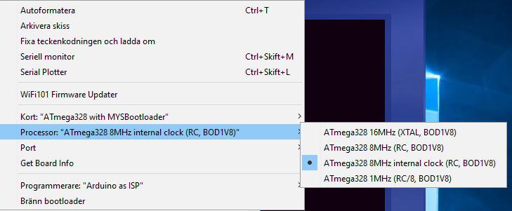
############################################################## MYSBL13.name=ATmega328 with MYSBootloader MYSBL13.upload.tool=avrdude MYSBL13.upload.protocol=arduino MYSBL13.bootloader.tool=avrdude MYSBL13.bootloader.unlock_bits=0x3F MYSBL13.bootloader.lock_bits=0x0F MYSBL13.build.mcu=atmega328p MYSBL13.build.board=AVR_PRO MYSBL13.build.core=arduino MYSBL13.build.variant=standard ## Arduino with MYSBootloader 1.3pre ## ------------------------------------------------- MYSBL13.menu.cpu.16MHzatmega328=ATmega328 16MHz (XTAL, BOD1V8) MYSBL13.menu.cpu.16MHzatmega328.upload.maximum_size=30720 MYSBL13.menu.cpu.16MHzatmega328.upload.maximum_data_size=2048 MYSBL13.menu.cpu.16MHzatmega328.upload.speed=115200 MYSBL13.menu.cpu.16MHzatmega328.bootloader.low_fuses=0xFF MYSBL13.menu.cpu.16MHzatmega328.bootloader.high_fuses=0xDA MYSBL13.menu.cpu.16MHzatmega328.bootloader.extended_fuses=0x06 MYSBL13.menu.cpu.16MHzatmega328.bootloader.file=MYSBootloader/MYSBL13pre_atmega328_16Mhz.hex MYSBL13.menu.cpu.16MHzatmega328.build.mcu=atmega328p MYSBL13.menu.cpu.16MHzatmega328.build.f_cpu=16000000L MYSBL13.menu.cpu.8MHzatmega328=ATmega328 8MHz (RC, BOD1V8) MYSBL13.menu.cpu.8MHzatmega328.upload.maximum_size=30720 MYSBL13.menu.cpu.8MHzatmega328.upload.maximum_data_size=2048 MYSBL13.menu.cpu.8MHzatmega328.upload.speed=38400 MYSBL13.menu.cpu.8MHzatmega328.bootloader.low_fuses=0xE2 MYSBL13.menu.cpu.8MHzatmega328.bootloader.high_fuses=0xDA MYSBL13.menu.cpu.8MHzatmega328.bootloader.extended_fuses=0x06 MYSBL13.menu.cpu.8MHzatmega328.bootloader.file=MYSBootloader/MYSBL13pre_atmega328_8Mhz.hex MYSBL13.menu.cpu.8MHzatmega328.build.mcu=atmega328p MYSBL13.menu.cpu.8MHzatmega328.build.f_cpu=8000000L ############# DO NOT WORK INTERNAL CLOCK ##################### MYSBL13.menu.cpu.8MHzinternalclockatmega328=ATmega328 8MHz internal clock (RC, BOD1V8) MYSBL13.menu.cpu.8MHzinternalclockatmega328.upload.maximum_size=30720 MYSBL13.menu.cpu.8MHzinternalclockatmega328.upload.maximum_data_size=2048 MYSBL13.menu.cpu.8MHzinternalclockatmega328.upload.speed=38400 MYSBL13.menu.cpu.8MHzinternalclockatmega328.upload.tool=arduino:avrdude MYSBL13.menu.cpu.8MHzinternalclockatmega328.upload.protocol=arduino MYSBL13.menu.cpu.8MHzinternalclockatmega328.bootloader.low_fuses=0xE2 MYSBL13.menu.cpu.8MHzinternalclockatmega328.bootloader.high_fuses=0xDA MYSBL13.menu.cpu.8MHzinternalclockatmega328.bootloader.extended_fuses=0xfe MYSBL13.menu.cpu.8MHzinternalclockatmega328.bootloader.file=breadboard/MYSBL13pre_atmega328_8Mhz.hex MYSBL13.menu.cpu.8MHzinternalclockatmega328.bootloader.unlock_bits=0x3F MYSBL13.menu.cpu.8MHzinternalclockatmega328.bootloader.lock_bits=0x0F MYSBL13.menu.cpu.8MHzinternalclockatmega328.bootloader.tool=arduino:avrdude MYSBL13.menu.cpu.8MHzinternalclockatmega328.build.mcu=atmega328p MYSBL13.menu.cpu.8MHzinternalclockatmega328.build.f_cpu=8000000L MYSBL13.menu.cpu.8MHzinternalclockatmega328.build.core=arduino:arduino MYSBL13.menu.cpu.8MHzinternalclockatmega328.build.variant=arduino:standard MYSBL13.menu.cpu.1MHzatmega328=ATmega328 1MHz (RC/8, BOD1V8) MYSBL13.menu.cpu.1MHzatmega328.upload.maximum_size=30720 MYSBL13.menu.cpu.1MHzatmega328.upload.maximum_data_size=2048 MYSBL13.menu.cpu.1MHzatmega328.upload.speed=9600 MYSBL13.menu.cpu.1MHzatmega328.bootloader.low_fuses=0x62 MYSBL13.menu.cpu.1MHzatmega328.bootloader.high_fuses=0xDA MYSBL13.menu.cpu.1MHzatmega328.bootloader.extended_fuses=0x06 MYSBL13.menu.cpu.1MHzatmega328.bootloader.file=MYSBootloader/MYSBL13pre_atmega328_1Mhz.hex MYSBL13.menu.cpu.1MHzatmega328.build.mcu=atmega328p MYSBL13.menu.cpu.1MHzatmega328.build.f_cpu=1000000L ##############################################################``` -
############################################################## MYSBL13.name=ATmega328 with MYSBootloader MYSBL13.upload.tool=avrdude MYSBL13.upload.protocol=arduino MYSBL13.bootloader.tool=avrdude MYSBL13.bootloader.unlock_bits=0x3F MYSBL13.bootloader.lock_bits=0x0F MYSBL13.build.mcu=atmega328p MYSBL13.build.board=AVR_PRO MYSBL13.build.core=arduino MYSBL13.build.variant=standard ## Arduino with MYSBootloader 1.3pre ## ------------------------------------------------- MYSBL13.menu.cpu.16MHzatmega328=ATmega328 16MHz (XTAL, BOD1V8) MYSBL13.menu.cpu.16MHzatmega328.upload.maximum_size=30720 MYSBL13.menu.cpu.16MHzatmega328.upload.maximum_data_size=2048 MYSBL13.menu.cpu.16MHzatmega328.upload.speed=115200 MYSBL13.menu.cpu.16MHzatmega328.bootloader.low_fuses=0xFF MYSBL13.menu.cpu.16MHzatmega328.bootloader.high_fuses=0xDA MYSBL13.menu.cpu.16MHzatmega328.bootloader.extended_fuses=0x06 MYSBL13.menu.cpu.16MHzatmega328.bootloader.file=MYSBootloader/MYSBL13pre_atmega328_16Mhz.hex MYSBL13.menu.cpu.16MHzatmega328.build.mcu=atmega328p MYSBL13.menu.cpu.16MHzatmega328.build.f_cpu=16000000L MYSBL13.menu.cpu.8MHzatmega328=ATmega328 8MHz (RC, BOD1V8) MYSBL13.menu.cpu.8MHzatmega328.upload.maximum_size=30720 MYSBL13.menu.cpu.8MHzatmega328.upload.maximum_data_size=2048 MYSBL13.menu.cpu.8MHzatmega328.upload.speed=38400 MYSBL13.menu.cpu.8MHzatmega328.bootloader.low_fuses=0xE2 MYSBL13.menu.cpu.8MHzatmega328.bootloader.high_fuses=0xDA MYSBL13.menu.cpu.8MHzatmega328.bootloader.extended_fuses=0x06 MYSBL13.menu.cpu.8MHzatmega328.bootloader.file=MYSBootloader/MYSBL13pre_atmega328_8Mhz.hex MYSBL13.menu.cpu.8MHzatmega328.build.mcu=atmega328p MYSBL13.menu.cpu.8MHzatmega328.build.f_cpu=8000000L ############# DO NOT WORK INTERNAL CLOCK ##################### MYSBL13.menu.cpu.8MHzinternalclockatmega328=ATmega328 8MHz internal clock (RC, BOD1V8) MYSBL13.menu.cpu.8MHzinternalclockatmega328.upload.maximum_size=30720 MYSBL13.menu.cpu.8MHzinternalclockatmega328.upload.maximum_data_size=2048 MYSBL13.menu.cpu.8MHzinternalclockatmega328.upload.speed=38400 MYSBL13.menu.cpu.8MHzinternalclockatmega328.upload.tool=arduino:avrdude MYSBL13.menu.cpu.8MHzinternalclockatmega328.upload.protocol=arduino MYSBL13.menu.cpu.8MHzinternalclockatmega328.bootloader.low_fuses=0xE2 MYSBL13.menu.cpu.8MHzinternalclockatmega328.bootloader.high_fuses=0xDA MYSBL13.menu.cpu.8MHzinternalclockatmega328.bootloader.extended_fuses=0xfe MYSBL13.menu.cpu.8MHzinternalclockatmega328.bootloader.file=breadboard/MYSBL13pre_atmega328_8Mhz.hex MYSBL13.menu.cpu.8MHzinternalclockatmega328.bootloader.unlock_bits=0x3F MYSBL13.menu.cpu.8MHzinternalclockatmega328.bootloader.lock_bits=0x0F MYSBL13.menu.cpu.8MHzinternalclockatmega328.bootloader.tool=arduino:avrdude MYSBL13.menu.cpu.8MHzinternalclockatmega328.build.mcu=atmega328p MYSBL13.menu.cpu.8MHzinternalclockatmega328.build.f_cpu=8000000L MYSBL13.menu.cpu.8MHzinternalclockatmega328.build.core=arduino:arduino MYSBL13.menu.cpu.8MHzinternalclockatmega328.build.variant=arduino:standard MYSBL13.menu.cpu.1MHzatmega328=ATmega328 1MHz (RC/8, BOD1V8) MYSBL13.menu.cpu.1MHzatmega328.upload.maximum_size=30720 MYSBL13.menu.cpu.1MHzatmega328.upload.maximum_data_size=2048 MYSBL13.menu.cpu.1MHzatmega328.upload.speed=9600 MYSBL13.menu.cpu.1MHzatmega328.bootloader.low_fuses=0x62 MYSBL13.menu.cpu.1MHzatmega328.bootloader.high_fuses=0xDA MYSBL13.menu.cpu.1MHzatmega328.bootloader.extended_fuses=0x06 MYSBL13.menu.cpu.1MHzatmega328.bootloader.file=MYSBootloader/MYSBL13pre_atmega328_1Mhz.hex MYSBL13.menu.cpu.1MHzatmega328.build.mcu=atmega328p MYSBL13.menu.cpu.1MHzatmega328.build.f_cpu=1000000L ##############################################################``` -
@MLs try to first upload the burning sketch to the nano (even if its already uploaded) and then burn the bootloader.
What set up do you have, how the nano is connected to the atmega?
What error do you get when bootloader burn fails?The problem is not to burn bootloader. The problem I think is that the Mysbootloader does not use internal clock.
Therefore, I asked you how to know how a bootloader uses an external clock or internal clock.
And because you had a bootloader for OTA and internal clock, 8MHz I wanted you to send it to me. -
The problem is not to burn bootloader. The problem I think is that the Mysbootloader does not use internal clock.
Therefore, I asked you how to know how a bootloader uses an external clock or internal clock.
And because you had a bootloader for OTA and internal clock, 8MHz I wanted you to send it to me.@MLs I am completely lost here, you said "I do not get Atmel to run with Mysbootloader 8MHz." and now you are asking "how to know how a bootloader uses an external clock or internal clock" how can you say its not working and then ask me how to know that its working?
To conclude this, if you successfully burn the 8Mhz Mysbootloader and the board is working then it is working with 8Mhz it cannot be working on 16Mhz because there is no external osc, its not 1Mhz because of the fuses etc.
-
@MLs I am completely lost here, you said "I do not get Atmel to run with Mysbootloader 8MHz." and now you are asking "how to know how a bootloader uses an external clock or internal clock" how can you say its not working and then ask me how to know that its working?
To conclude this, if you successfully burn the 8Mhz Mysbootloader and the board is working then it is working with 8Mhz it cannot be working on 16Mhz because there is no external osc, its not 1Mhz because of the fuses etc.
@MLs said in Another simple (No SMT) relay actuator:
Feeling a bit confused how do you know that a bootloader uses the internal clock?
Because I used another bootloader after installing your card, I did not get the Atmega circuit to run. But if I used this bootloader, I started the Atmega circuit and everything worked.But what makes the internal clock in used?
I use a UNO when I'm burning bootloader and do not know if you can change fuses and clock option.If you use a bootloader that uses an external clock, you will not get the Atmega circuit to run. If I understand everything right.
No if I'm burning 8MHz Mysbootloader, the Atmega circuit does not start.
But instead, I use this bootloader (ATmega328 on a 8 MHz internal clock) and I get the Atmega circuit to run, but without OTA.
-
@MLs said in Another simple (No SMT) relay actuator:
Feeling a bit confused how do you know that a bootloader uses the internal clock?
Because I used another bootloader after installing your card, I did not get the Atmega circuit to run. But if I used this bootloader, I started the Atmega circuit and everything worked.But what makes the internal clock in used?
I use a UNO when I'm burning bootloader and do not know if you can change fuses and clock option.If you use a bootloader that uses an external clock, you will not get the Atmega circuit to run. If I understand everything right.
No if I'm burning 8MHz Mysbootloader, the Atmega circuit does not start.
But instead, I use this bootloader (ATmega328 on a 8 MHz internal clock) and I get the Atmega circuit to run, but without OTA.
@MLs said in Another simple (No SMT) relay actuator:
@MLs said in Another simple (No SMT) relay actuator:
Feeling a bit confused how do you know that a bootloader uses the internal clock?
Because I used another bootloader after installing your card, I did not get the Atmega circuit to run. But if I used this bootloader, I started the Atmega circuit and everything worked.But what makes the internal clock in used?
I use a UNO when I'm burning bootloader and do not know if you can change fuses and clock option.If you use a bootloader that uses an external clock, you will not get the Atmega circuit to run. If I understand everything right.
No if I'm burning 8MHz Mysbootloader, the Atmega circuit does not start.
But instead, I use this bootloader (ATmega328 on a 8 MHz internal clock) and I get the Atmega circuit to run, but without OTA.
Therefore, I asked you how to know how a bootloader uses an external clock or internal clock.
-
@MLs said in Another simple (No SMT) relay actuator:
Feeling a bit confused how do you know that a bootloader uses the internal clock?
Because I used another bootloader after installing your card, I did not get the Atmega circuit to run. But if I used this bootloader, I started the Atmega circuit and everything worked.But what makes the internal clock in used?
I use a UNO when I'm burning bootloader and do not know if you can change fuses and clock option.If you use a bootloader that uses an external clock, you will not get the Atmega circuit to run. If I understand everything right.
No if I'm burning 8MHz Mysbootloader, the Atmega circuit does not start.
But instead, I use this bootloader (ATmega328 on a 8 MHz internal clock) and I get the Atmega circuit to run, but without OTA.
-
@MLs You said before "The problem is not to burn bootloader."
and now you are saying "No if I'm burning 8MHz Mysbootloader, the Atmega circuit does not start."I am asking again, are you able to successfully burn and run Mysbootloader 8Mhz or not?
I can burn Mysbootloader yes.
But the Atmega circuit does not start.
The problem I think is that Mysbootloader does not use the internal clockAnd because you said you had a bootloader for OTA and internal clock, 8MHz I wanted you to send it to me.
Then there would have been no problem, I think.
-
I can burn Mysbootloader yes.
But the Atmega circuit does not start.
The problem I think is that Mysbootloader does not use the internal clockAnd because you said you had a bootloader for OTA and internal clock, 8MHz I wanted you to send it to me.
Then there would have been no problem, I think.
-
@MLs i use what you use, Mysbotloader 1.3pre, as i said in one of the first messages, you dont need me to send it to you you can (and did) download it from here.
This is why i think you are doing something wrong or have wrong settings.
-
Is this setup to take a maximum 2 amp load? Plenty for a lighting circuit, just curious in case someone tries to use it on a switched outlet circuit etc.
J1 is power feed and J2 are the three switched outputs right with the wall switch connected using D5 - D6 - D7 right?
-
Is this setup to take a maximum 2 amp load? Plenty for a lighting circuit, just curious in case someone tries to use it on a switched outlet circuit etc.
J1 is power feed and J2 are the three switched outputs right with the wall switch connected using D5 - D6 - D7 right?
@Shaun-Storbakken It was designed with the idea of controlling 3 different loads of up to 2 Amp each, lightning, switches etc.
The D-5,6,7 are for manual switching and they will (if you use my code) control the 3 relays respectively, J1 is power input 110-220V, please note that you should pay attention to the polarity and connect line wire to the right of J1 (otherwise you will end up switching natural to the load), J2 is AC output where each one is different relay, so you have 3 X 110-220V outputs of max 2 A each.I hope it was helpful, please let me know if you need further help.
-
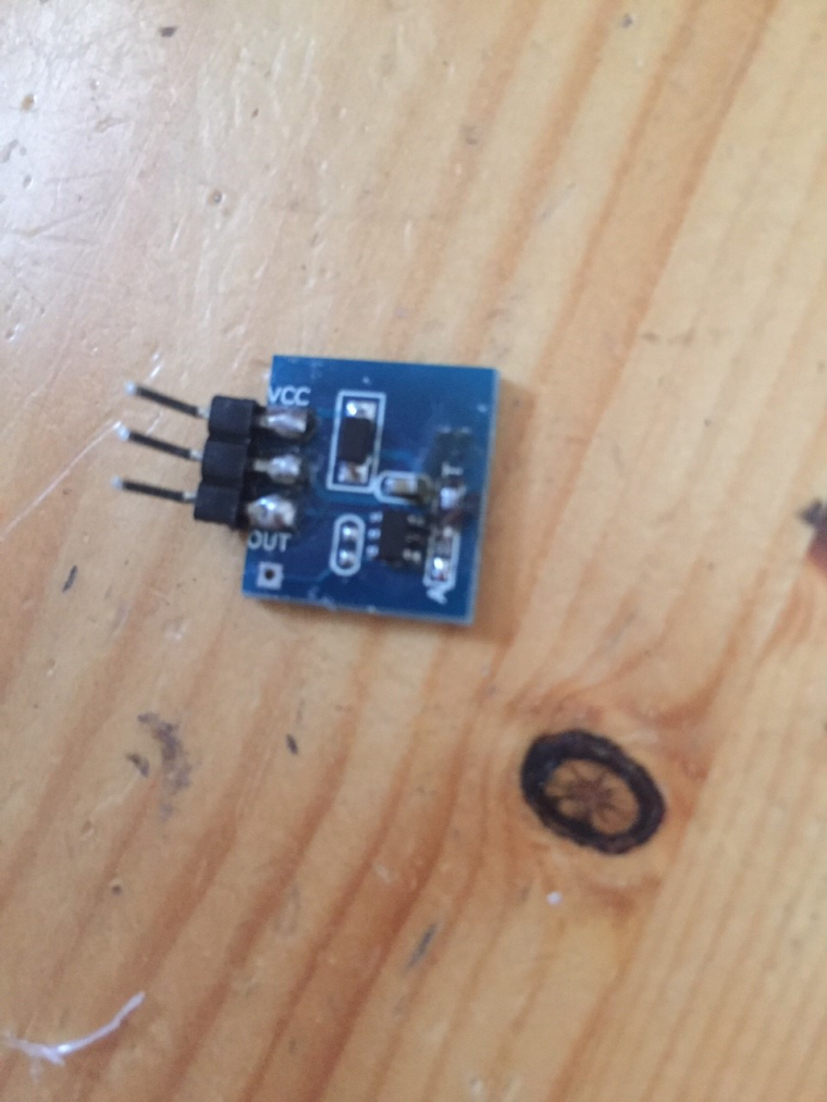
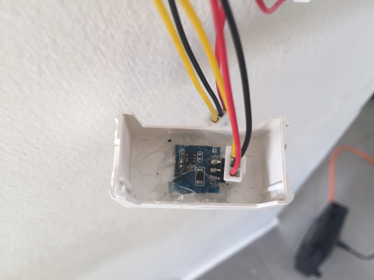
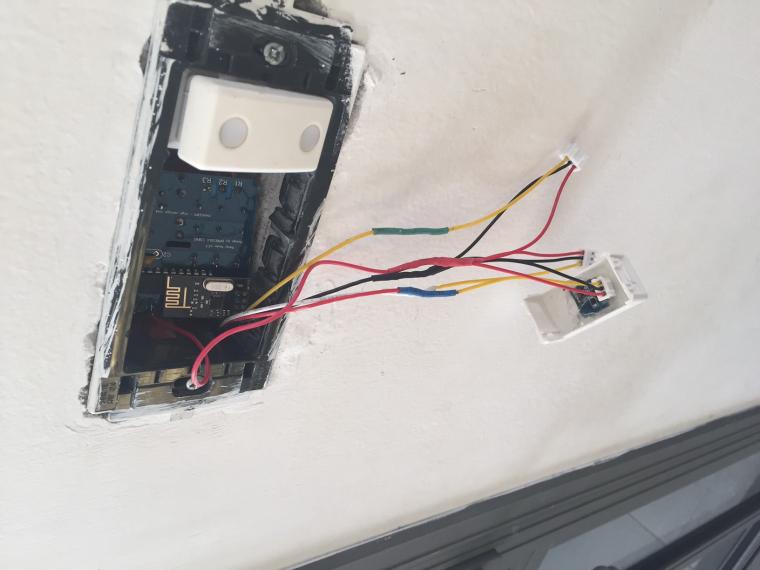
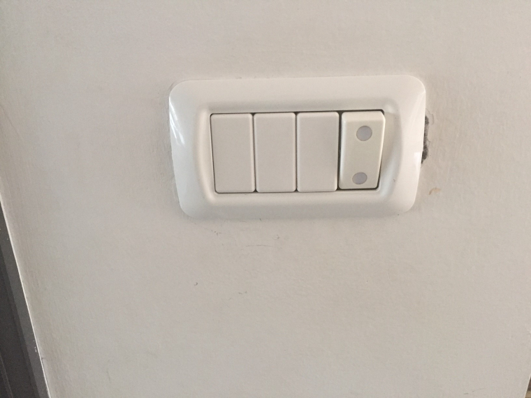
Small update, i connected touch switches to the board instead of mechanical switches.
where i live we are using gwiss switches and when the board is in the box there is not much room for mechanical switches as they are too deep, so i took some blanks that are used to cover unused switch hols and added touch switch to it, see the pictures below: