[Tutorial] How to burn 1Mhz & 8Mhz bootloader using Arduino IDE 1.6.5-r5


  • Hello everyone,

    Last week I received my slim node board designed by m26872 and begun the process of burning the 1Mhz bootloader. I faced some problems for a couple of hours and google helped me to successfully burn it and uploading the sketch.
    Please correct me if I missed something. I tried to re-do the steps now before writing the post to make sure it works.

    I am using Arduino IDE 1.6.5-r5 with Arduino UNO board.
    I used some photos from arduino.cc
    I will explain flashing both 8Mhz and 1Mhz configurations.

    1- You will need the following

    • Arduino UNO ( didn't test using other boards)
    • Atmega328p chip ( with preloaded bootloader or without )
    • Breadboard
    • Wires
    • Crystal ( optional )

    2-

    • Connect your arduino UNO to your laptop.
    • Open Arduino IDE.
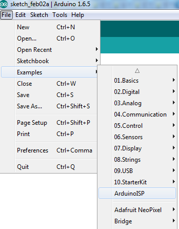
    • Go to File > Examples > Arduino ISP

    0_1454446970268_1.png

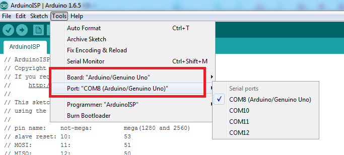
    • Go to Tools and make sure you choose Arduino/Genuino Uno and you COM port.
      Your COM port may be different than mine

    0_1454447281880_2.png

    Note: The following step solved my problem when I failed to upload the bootloader at the beginning.

    • Go to Tools > Programmer > Arduino as ISP

    Make sure to choose "Arduino as ISP" not "ArduinoISP"

    0_1454447412898_3.png

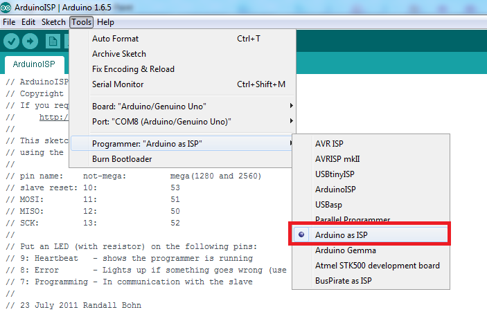
    Then upload your ArduinoISP sketch.

    • It will take less than a minute.
    • Close the sketch ArduinoISP adter uploading successfully.

    *********************************** . ***********************************
    *********************** Burning the bootloader ***********************
    *********************************** . ***********************************

    3- For burning the bootloader you have to set your environment as shown in the figure below:
    Remove the arduino usb cable and begin wiring.

    0_1454446598443_4.png

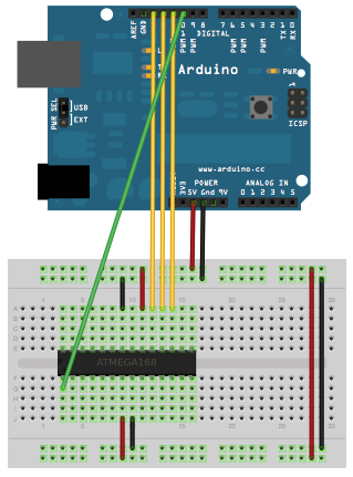
    Double check your wires and make sure they are connected in the correct pin.

    *********************************** . ***********************************
    ********************** Burning 8Mhz bootloader **********************
    *********************************** . ***********************************

    Quoted from Arduino.cc :

    • Download this hardware configuration archive: breadboard-1-6-x.zip
    • Extract the zip file. A folder with name "breadboard" will appear.
    • Open your Arduino folder path and move the breadboard folder from the zip archive to the "hardware" folder of your Arduino sketchbook.
    • Restart the Arduino software.
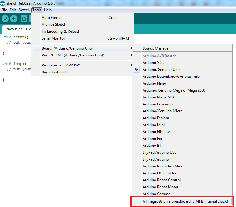
      You should see "ATmega328 on a breadboard (8 MHz internal clock)" in the Tools > Board menu.
    • Be sure to select "ATmega328 on a breadboard (8 MHz internal clock)" when burning the bootloader.(If you select the wrong item and configure the microcontroller to use an external clock, it won't work unless you connect one.)
    • Once you've done this, you can burn the bootloader and upload programs onto your ATmega328p. To burn the bootloader go to Tools > Burn bootloader

    0_1454448243570_5.png

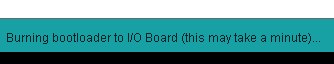
    It will take less than a minute and leds will flash. Wait until bootloader is burned.

    0_1454448363854_6.png

    *********************************** . ***********************************
    ********************** Burning 1Mhz bootloader **********************
    *********************************** . ***********************************

    • I followed m26872 guides in his project My Slim 2AA Battery Node to get the 1Mhz bootloader. I'll copy some of his instructions.

    • I use this precompiled bootloader from here. It's an Optiboot with 1MHz internal clock and 9600 baud serial communication. Fuse changed to BOD disable.

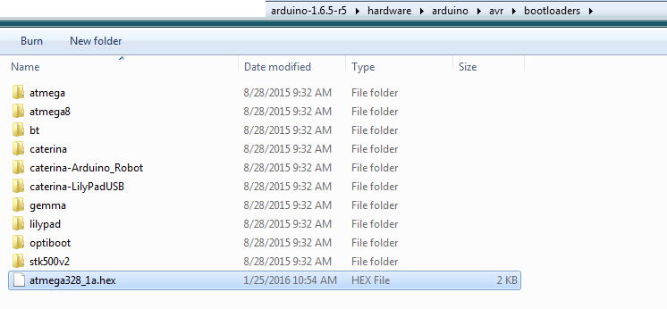
    • Rename your .hex to atmega328_1a.hex

    • Move it to "ARDUINO_PATH" > hardware > arduino > avr > bootloaders

    0_1454448897446_8.png

    • We need to add the new board to the boards.txt file located at "ARDUINO_PATH" > hardware > arduino > avr
    • Open boards.txt
    • Go to this link.
    • Copy the content of the link and paste it at the end of boards.txt

    0_1454449112046_9.png

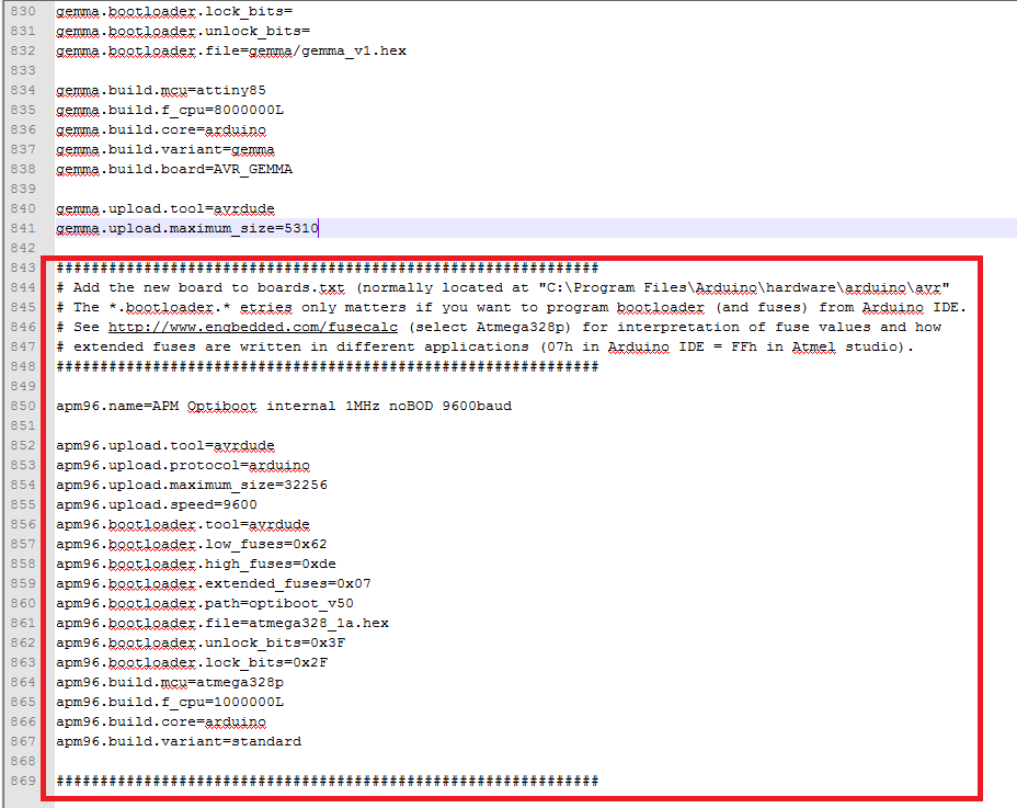
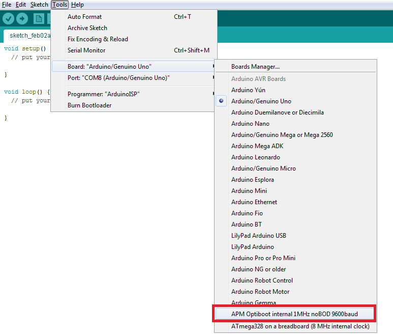
    • Restart you Arduino IDE.
    • You should see "APM Optiboot internal 1Mhz noBOD 9600baud" in the Tools > Board menu.
    • Once you've done this, you can burn the bootloader and upload programs onto your ATmega328p. To burn the bootloader go to Tools > Burn bootloader

    0_1454451123401_10.png

    Tips about burning the bootloader if it failed:

    1- I faced the following issues and was solved as follows:

    avrdude: Yikes! Invalid device signature.
    Double check connections and try again, or use -F to override

    • Maybe your chip is configured to run on an external crystal clock. I tested with two values and it succeeded. I used 10Mhz and 20Mhz as I didn't have 16 Mhz.
    • Connect the crystal to pin 9 and 10
    • Note: You won't need the crystal except for the first time as the new bootloader is configured to run on internal 1Mhz or 8Mhz.

    2-

    avrdude: Error: Could not find USBtiny device (0x2341/0x49)

    Make sure you chose "Arduino as ISP" not "ArduinoISP" from the programmer list. You will find it in Tools menu.

    3-

    avrdude: can't open input file D:\arduino-1.6.5-r5\hardware\arduino\avr/bootloaders/atmega328_1a.hex: No such file or directory
    avrdude: read from file 'D:\arduino-1.6.5-r5\hardware\arduino\avr/bootloaders/atmega328_1a.hex' failed
    Error while burning bootloader.

    Your .hex file is not in the correct path.

    • According to the .boards file, the path is configured to be in the default path arduino-1.6.5-r5\hardware\arduino\avr\bootloaders

    You can find this configuration in the boards.txt as follows:
    apm96.bootloader.file=atmega328_1a.hex

    If you wish to put the .hex file in a folder, so you will have to edit the path above in the boards.txt

    Example:You put the .hex file in > arduino-1.6.5-r5\hardware\arduino\avr\bootloaders\MyOneMhz
    So change the line to this: apm96.bootloader.file=MyOneMhz/atmega328_1a.hex

    *********************************** . ***********************************
    ********************** End of burning bootloader **********************
    *********************************** . ***********************************

    *********************************** . ***********************************
    ************************ Uploading the sketch *************************
    *********************************** . ***********************************

    4- Once your ATmega328p has the Arduino bootloader on it, you can upload programs to it using the USB-to-serial convertor (FTDI chip) on an Arduino board. To do so, you remove the microcontroller from the Arduino board so the FTDI chip can talk to the microcontroller on the breadboard instead.

    • Set the environment as follows:
      The picture at the bottom shows how to connect the RX and TX lines from the Arduino UNO board to the ATmega on the breadboard.

    0_1454449899848_7.png

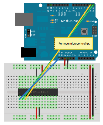
    After finishing wiring and recheck connections:

    • Choose your desired board which we have added before and burned the atmega328p with it.
    • Upload your sketch normally.
    • Leds will flash in the Arduino UNO board.
    • Sketch will take some time with 1Mhz and it is faster with 8Mhz because of the baud rate chosen in 1Mhz.

    *********************************** . ***********************************
    *************************** ** References ** **************************
    *********************************** . ***********************************

    *********************************** . ***********************************
    *************************** ** THE END ** *****************************
    *********************************** . ***********************************

    I hope it was clear enough and doesn't contain mistakes. Please let me know if something was missing.
    I encourage you to add your tips and tricks so that we can learn.

    Thanks.


  • Nice work.... that would have been handy a few days ago 🙂 i had to figure out burn bootloader as well

    If its any help to anyone else. the setting bootloader.extended_fuses=0x04 - changes the BOD to 4.3v

    Had to use it on a 5v board as the original 2.7v caused lockups when had low voltage (was running board off solar panel)


  • Hardware Contributor

    Here are all the possible values:

    bootloader.extended_fuses=0x04 -> BOD at 4.3V
    bootloader.extended_fuses=0x05 -> BOD at 2.7V
    bootloader.extended_fuses=0x06 -> BOD at 1.8V
    bootloader.extended_fuses=0x07 -> BOD disabled


  • @GertSanders said:

    Here are all the possible values:

    bootloader.extended_fuses=0x04 -> BOD at 4.3V
    bootloader.extended_fuses=0x05 -> BOD at 2.7V
    bootloader.extended_fuses=0x06 -> BOD at 1.8V
    bootloader.extended_fuses=0x07 -> BOD disabled

    How low(volt) can you go when BOD disabled?


  • Hardware Contributor

    @flopp The atmega seems to function down to 1.6V (lowest I measured it). Depends on the working frequency. Check the datasheet. There are variations in each production batch.

    The NRF24L01+ can only go down to 1.9V. My guess is that some modules do work at lower voltages at 250KBit rates, but then more transmission errors are possible.

    With two AA batteries in series, going from 3V down to 1.9V and a node with an average consumption of les then 10 uA, I think you can get more then 1 year life out of it.


  • @GertSanders
    Wow 1 year. I will try this tut in the weekend.


  • Hardware Contributor

    @flopp Not with a standard Arduino board, but with a Sensebender Micro or any board with power consumption below 10uA. An atmega328p on a breadboard is the simplest case. For a very good tutorial go here: http://www.gammon.com.au/breadboard

    If you need an assembled board: https://www.openhardware.io/view/1/Sensebender-Micro.

    It is the officially supported board for MySensors library. On OpenHardware.io you will find more options.

    Have fun !


  • @GertSanders
    Ok, I have read somewhere that a Pro Mini can go down to 1.8v, not possible?


  • Hardware Contributor

    @flopp A pro-mini can do this if the fuses are set properly (when powering via Vcc for instance). If you power the Pro Mini via the "raw" pin, then power passes through the on board power regulator first, and this one will not allow 1.8V as far as I know.


  • @GertSanders
    Good to hear. I will reply how it went


  • Hardware Contributor

    @flopp look for messages on power saving on pro mini on this forum.


  • hi @ahmedadelhosni

    Thank you for the tutorial. Quick question: Is it possible to just take the Atmega 328 chip with the freshly flashed bootloader, and just stick in in the Arduino Uno to program a sketch?


  • Hardware Contributor

    @drock1985 I think I have done just that. It only needs to have a bootloader (you could just flash one there though).


  • I have successfully burned a new bootloader to a pro mini clone, now I can run it down to 1,8V(I think) tried 2,6V and it still works

    Thanks for a great tut


  • Awesome @LastSamurai thanks.

    One other question: Is it possible to just use a standard USB to FTDI converter to flash the sketch? Ex: flash bootloader using an Uno, then install in a SlimNode and use the FTDI connector there to flash?


  • Hardware Contributor

    @drock1985 Yes once it has a bootloader that should be possible (you need to use the right settings though 😉 )


  • @LastSamurai

    What settings would those be? Would they be things outside of the tutorial?

    Sorry to ask so many questions. Never flashed an Arduino before outside of connecting a USB cable to an Uno or Nano


  • Hardware Contributor

    @drock1985 Mainly the baudrate but if you just burn the standard e.g. Arduino Uno bootloader and then use the IDE with the Uno settings everything should work fine. If you encounter errors you can still check your settings 😉 They are in the boards.txt file of the IDE.

    Just try it though, it really isn't that hard 😉


  • very good work instruction, thank you !! 👍


  • Hi there, and thanks for the tutorial. I'm trying this for the first time (the ATmega is going to be used in a slim temp node), and I'm receiving this message you mentioned:

    avrdude: Yikes! Invalid device signature.
    Double check connections and try again, or use -F to override
    

    You mention we should try the following:

    Maybe your chip is configured to run on an external crystal clock. I tested with two values and it succeeded. I used 10Mhz and 20Mhz as I didn't have 16 Mhz.
    Connect the crystal to pin 9 and 10
    Note: You won't need the crystal except for the first time as the new bootloader is configured to run on internal 1Mhz or 8Mhz.
    

    I don't quite follow what this means? Do I need a 10mhz, 16mhz or 20mhz crystal attached to the breadboard like you show in the video? If so, is that the only change I would need to make?

    FYI I'm using an Arduino clone (Buono uno r3, set at 5V)


  • @rsachoc Maybe I need to rephrase the sentence 🙂
    I meant that any crystal value will work. I didn't have 16Mhz, but I had the values 10Mhz and 20 Mhz. So I tested with 10 Mhz and I bypassed the error and didn't come again. I wanted to know further whether the crystal value is important or not. So I got another chip with preloaded arduino bootloader, and tested with 20Mhz. Also I succeeded. Thus I assume that you can use any value for this step .

    I am also using Uno clone and this is the only thing I did regarding this issue. I didn't even add capacitors to the crystal. Just put any value and test.


  • @ahmedadelhosni thanks! I'm going to grab a 10mhz and 16mhz to test later this evening. Just to confirm from what you've said, I don't need the capacitors? I know in the youtube vid there were capacitors used?


  • @rsachoc yes. I didn't also have caps and it worked 🙂


  • @rsachoc ofcourse if you have 16Mhz and capacitors like the reference video, that would be great. but if you were in a hurry and lazy to buy some, so just do it like so.
    Edit: 16* Mhz not 10 Mhz


  • @ahmedadelhosni I have some capacitors, but no crystals, so I'm picking a 10mhz and 16mhz up later today. I'll try with just the capacitors first and see how I go.

    Thanks!


  • @rsachoc edit: sorry I meant 16. Like the normal arduino board


  • C:\Users\James\Desktop\RPi Openhab\arduino-1.6.7-windows\hardware\tools\avr/bin/avrdude -CC:\Users\James\Desktop\RPi Openhab\arduino-1.6.7-windows\hardware\tools\avr/etc/avrdude.conf -v -patmega328p -cstk500v1 -PCOM5 -b19200 -e -Ulock:w:0x3F:m -Uefuse:w:0x05:m -Uhfuse:w:0xDE:m -Ulfuse:w:0xFF:m 
    
    avrdude: Version 6.0.1, compiled on Apr 15 2015 at 19:59:58
             Copyright (c) 2000-2005 Brian Dean, http://www.bdmicro.com/
             Copyright (c) 2007-2009 Joerg Wunsch
    
             System wide configuration file is "C:\Users\James\Desktop\RPi Openhab\arduino-1.6.7-windows\hardware\tools\avr/etc/avrdude.conf"
    
             Using Port                    : COM5
             Using Programmer              : stk500v1
             Overriding Baud Rate          : 19200
             AVR Part                      : ATmega328P
             Chip Erase delay              : 9000 us
             PAGEL                         : PD7
             BS2                           : PC2
             RESET disposition             : dedicated
             RETRY pulse                   : SCK
             serial program mode           : yes
             parallel program mode         : yes
             Timeout                       : 200
             StabDelay                     : 100
             CmdexeDelay                   : 25
             SyncLoops                     : 32
             ByteDelay                     : 0
             PollIndex                     : 3
             PollValue                     : 0x53
             Memory Detail                 :
    
                                      Block Poll               Page                       Polled
               Memory Type Mode Delay Size  Indx Paged  Size   Size #Pages MinW  MaxW   ReadBack
               ----------- ---- ----- ----- ---- ------ ------ ---- ------ ----- ----- ---------
               eeprom        65    20     4    0 no       1024    4      0  3600  3600 0xff 0xff
               flash         65     6   128    0 yes     32768  128    256  4500  4500 0xff 0xff
               lfuse          0     0     0    0 no          1    0      0  4500  4500 0x00 0x00
               hfuse          0     0     0    0 no          1    0      0  4500  4500 0x00 0x00
               efuse          0     0     0    0 no          1    0      0  4500  4500 0x00 0x00
               lock           0     0     0    0 no          1    0      0  4500  4500 0x00 0x00
               calibration    0     0     0    0 no          1    0      0     0     0 0x00 0x00
               signature      0     0     0    0 no          3    0      0     0     0 0x00 0x00
    
             Programmer Type : STK500
             Description     : Atmel STK500 Version 1.x firmware
             Hardware Version: 2
             Firmware Version: 1.18
             Topcard         : Unknown
             Vtarget         : 0.0 V
             Varef           : 0.0 V
             Oscillator      : Off
             SCK period      : 0.1 us
    
    avrdude: AVR device initialized and ready to accept instructions
    
    Reading | ################################################## | 100% 0.02s
    
    avrdude: Device signature = 0x1e950f
    avrdude: erasing chip
    avrdude: reading input file "0x3F"
    avrdude: writing lock (1 bytes):
    
    Writing | ################################################## | 100% 0.01s
    
    avrdude: 1 bytes of lock written
    avrdude: verifying lock memory against 0x3F:
    avrdude: load data lock data from input file 0x3F:
    avrdude: input file 0x3F contains 1 bytes
    avrdude: reading on-chip lock data:
    
    C:\Users\James\Desktop\RPi Openhab\arduino-1.6.7-windows\hardware\tools\avr/bin/avrdude -CC:\Users\James\Desktop\RPi Openhab\arduino-1.6.7-windows\hardware\tools\avr/etc/avrdude.conf -v -patmega328p -cstk500v1 -PCOM5 -b19200 -Uflash:w:C:\Users\James\Desktop\RPi Openhab\arduino-1.6.7-windows\hardware\arduino\avr/bootloaders/optiboot/optiboot_atmega328.hex:i -Ulock:w:0x0F:m 
    Reading | ################################################## | 100% 0.01s
    
    avrdude: verifying ...
    avrdude: 1 bytes of lock verified
    avrdude: reading input file "0x05"
    avrdude: writing efuse (1 bytes):
    
    Writing | ################################################## | 100% 0.01s
    
    avrdude: 1 bytes of efuse written
    avrdude: verifying efuse memory against 0x05:
    avrdude: load data efuse data from input file 0x05:
    avrdude: input file 0x05 contains 1 bytes
    avrdude: reading on-chip efuse data:
    
    Reading | ################################################## | 100% 0.01s
    
    avrdude: verifying ...
    avrdude: 1 bytes of efuse verified
    avrdude: reading input file "0xDE"
    avrdude: writing hfuse (1 bytes):
    
    Writing | ################################################## | 100% 0.01s
    
    avrdude: 1 bytes of hfuse written
    avrdude: verifying hfuse memory against 0xDE:
    avrdude: load data hfuse data from input file 0xDE:
    avrdude: input file 0xDE contains 1 bytes
    avrdude: reading on-chip hfuse data:
    
    Reading | ################################################## | 100% 0.01s
    
    avrdude: verifying ...
    avrdude: 1 bytes of hfuse verified
    avrdude: reading input file "0xFF"
    avrdude: writing lfuse (1 bytes):
    
    Writing | ################################################## | 100% 0.01s
    
    avrdude: 1 bytes of lfuse written
    avrdude: verifying lfuse memory against 0xFF:
    avrdude: load data lfuse data from input file 0xFF:
    avrdude: input file 0xFF contains 1 bytes
    avrdude: reading on-chip lfuse data:
    
    Reading | ################################################## | 100% 0.01s
    
    avrdude: verifying ...
    avrdude: 1 bytes of lfuse verified
    
    avrdude done.  Thank you.
    
    
    avrdude: Version 6.0.1, compiled on Apr 15 2015 at 19:59:58
             Copyright (c) 2000-2005 Brian Dean, http://www.bdmicro.com/
             Copyright (c) 2007-2009 Joerg Wunsch
    
             System wide configuration file is "C:\Users\James\Desktop\RPi Openhab\arduino-1.6.7-windows\hardware\tools\avr/etc/avrdude.conf"
    
             Using Port                    : COM5
             Using Programmer              : stk500v1
             Overriding Baud Rate          : 19200
             AVR Part                      : ATmega328P
             Chip Erase delay              : 9000 us
             PAGEL                         : PD7
             BS2                           : PC2
             RESET disposition             : dedicated
             RETRY pulse                   : SCK
             serial program mode           : yes
             parallel program mode         : yes
             Timeout                       : 200
             StabDelay                     : 100
             CmdexeDelay                   : 25
             SyncLoops                     : 32
             ByteDelay                     : 0
             PollIndex                     : 3
             PollValue                     : 0x53
             Memory Detail                 :
    
                                      Block Poll               Page                       Polled
               Memory Type Mode Delay Size  Indx Paged  Size   Size #Pages MinW  MaxW   ReadBack
               ----------- ---- ----- ----- ---- ------ ------ ---- ------ ----- ----- ---------
               eeprom        65    20     4    0 no       1024    4      0  3600  3600 0xff 0xff
               flash         65     6   128    0 yes     32768  128    256  4500  4500 0xff 0xff
               lfuse          0     0     0    0 no          1    0      0  4500  4500 0x00 0x00
               hfuse          0     0     0    0 no          1    0      0  4500  4500 0x00 0x00
               efuse          0     0     0    0 no          1    0      0  4500  4500 0x00 0x00
               lock           0     0     0    0 no          1    0      0  4500  4500 0x00 0x00
               calibration    0     0     0    0 no          1    0      0     0     0 0x00 0x00
               signature      0     0     0    0 no          3    0      0     0     0 0x00 0x00
    
             Programmer Type : STK500
             Description     : Atmel STK500 Version 1.x firmware
             Hardware Version: 2
             Firmware Version: 1.18
             Topcard         : Unknown
             Vtarget         : 0.0 V
             Varef           : 0.0 V
             Oscillator      : Off
             SCK period      : 0.1 us
    
    avrdude: AVR device initialized and ready to accept instructions
    
    Reading | ################################################## | 100% 0.02s
    
    avrdude: Device signature = 0x1e950f
    avrdude: NOTE: "flash" memory has been specified, an erase cycle will be performed
             To disable this feature, specify the -D option.
    avrdude: erasing chip
    avrdude: reading input file "C:\Users\James\Desktop\RPi Openhab\arduino-1.6.7-windows\hardware\arduino\avr/bootloaders/optiboot/optiboot_atmega328.hex"
    avrdude: writing flash (32768 bytes):
    
    Writing | ################################################## | 100% 0.00s
    
    avrdude: 32768 bytes of flash written
    avrdude: verifying flash memory against C:\Users\James\Desktop\RPi Openhab\arduino-1.6.7-windows\hardware\arduino\avr/bootloaders/optiboot/optiboot_atmega328.hex:
    avrdude: load data flash data from input file C:\Users\James\Desktop\RPi Openhab\arduino-1.6.7-windows\hardware\arduino\avr/bootloaders/optiboot/optiboot_atmega328.hex:
    avrdude: input file C:\Users\James\Desktop\RPi Openhab\arduino-1.6.7-windows\hardware\arduino\avr/bootloaders/optiboot/optiboot_atmega328.hex contains 32768 bytes
    avrdude: reading on-chip flash data:
    
    Reading | ################################################## | 100% -0.00s
    
    avrdude: verifying ...
    avrdude: 32768 bytes of flash verified
    avrdude: reading input file "0x0F"
    avrdude: writing lock (1 bytes):
    
    Writing | ################################################## | 100% 0.02s
    
    avrdude: 1 bytes of lock written
    avrdude: verifying lock memory against 0x0F:
    avrdude: load data lock data from input file 0x0F:
    avrdude: input file 0x0F contains 1 bytes
    avrdude: reading on-chip lock data:
    
    Reading | ################################################## | 100% 0.01s
    
    avrdude: verifying ...
    avrdude: 1 bytes of lock verified
    
    avrdude done.  Thank you.
    

    Did I burn the bootloader successfully? The video indicates it should take longer, this literally took less than a second?


  • @rsachoc I haven't burned a bootloader since I have did this topic, but I do remember that it took like 2 seconds. It was really fast.
    You can try flashing the code to verify that it works well.


  • @ahmedadelhosni good idea, I hadn't thought of that. I'm going to have to build a slim temp node first, as my current chip is soldered to the board with no bootloader.


  • Hardware Contributor

    Hey guys, I have been building my own sensor nodes that should consume as little power as needed, so I burned a 1MHz bootloader with lower BOD settings which I found in the "slime 2AA battery node" thread (I guess this here is the same one).

    I had some problem with the node afterwards, which I fixed by setting the baudrate of the mysensors library to 9600. It seems like that is needed (too), beside settings the upload speeds. Can you guys confirm that? If so I would suggest adding that to the (great) manual!


  • @LastSamurai I've been advised that setting the baud rate in myconfig.h is the correct way to get things working when uploading sketches to the slim node. Don't think it matters when burining the bootloader though.


  • @LastSamurai I have faced this problem a couple of times but I don't remember how do I solve it. I just keep trying different solution. But I have to say thay I am using development branch and I don't redefine the baud rate if I don't wan't the serial debug.


  • thx for the tutorial. I perfomred every step you described, but I get errors when trying to upload a sketch:

    And I also get this error message:

    I tried to upload the 1MHz version

    edit:

    some more info form verbose mode output:

    edit2:

    Another problem: I could burn the bootloader on to one of my ATMega328 MCU´s but I needed to use a 16MHz Crystal when uploading for the first time. Now I can just burn and burn the bootloader again. Here ist the output:

    But it is the only MCU that works, all the other give the "Yikes" error, also when 16MHz Crystal is connected:

    Any explanation?

    - bootloader burning problem solved by rebuilding the wiring.

    - for some reason I could upload the sketch now, don´t ask me why. In the end I just reuploaded again and again...I hope I will be able to upload sketches to the next MCU´s as well

    Sorry for asking so many questions, but after spending hours and hours of setting up a raspberry pi with openhab, MQTT Broker and MQTT Gateway I am so close to finishing my first standalone sensor and it´s not going any further, I could cry 😢


  • Hi,

    Maybe someone in here can help me. I can't seem to compile any sketches on my Arduino IDE and keep getting errors spit at me. I can burn the bootloader with no problem but not any sketches. Any advice/ideas please? I'm running out of things to try. 😞


    C:\Program Files (x86)\Arduino\arduino-builder -dump-prefs -logger=machine -hardware "C:\Program Files (x86)\Arduino\hardware" -hardware "C:\Users\derri\AppData\Local\Arduino15\packages" -hardware "F:\Users.New\Derrick\Documents\Arduino\hardware" -tools "C:\Program Files (x86)\Arduino\tools-builder" -tools "C:\Program Files (x86)\Arduino\hardware\tools\avr" -tools "C:\Users\derri\AppData\Local\Arduino15\packages" -built-in-libraries "C:\Program Files (x86)\Arduino\libraries" -libraries "F:\Users.New\Derrick\Documents\Arduino\libraries" -fqbn=MySensors:avr:apm96 -ide-version=10608 -build-path "C:\Users\derri\AppData\Local\Temp\build782cd686753c1d06c6f3cef0b1b5a173.tmp" -warnings=none -prefs=build.warn_data_percentage=75 -verbose "C:\Users\derri\AppData\Local\Temp\untitled808982838.tmp\sketch_apr18a\sketch_apr18a.ino"
    C:\Program Files (x86)\Arduino\arduino-builder -compile -logger=machine -hardware "C:\Program Files (x86)\Arduino\hardware" -hardware "C:\Users\derri\AppData\Local\Arduino15\packages" -hardware "F:\Users.New\Derrick\Documents\Arduino\hardware" -tools "C:\Program Files (x86)\Arduino\tools-builder" -tools "C:\Program Files (x86)\Arduino\hardware\tools\avr" -tools "C:\Users\derri\AppData\Local\Arduino15\packages" -built-in-libraries "C:\Program Files (x86)\Arduino\libraries" -libraries "F:\Users.New\Derrick\Documents\Arduino\libraries" -fqbn=MySensors:avr:apm96 -ide-version=10608 -build-path "C:\Users\derri\AppData\Local\Temp\build782cd686753c1d06c6f3cef0b1b5a173.tmp" -warnings=none -prefs=build.warn_data_percentage=75 -verbose "C:\Users\derri\AppData\Local\Temp\untitled808982838.tmp\sketch_apr18a\sketch_apr18a.ino"
    Board MySensors:avr:apm96 doesn't define a 'build.board' preference. Auto-set to: AVR_APM96
    WARNING: Category '' in library UIPEthernet is not valid. Setting to 'Uncategorized'
    Warning: platform.txt from core 'MySensors AVR based boards' contains deprecated recipe.ar.pattern="{compiler.path}{compiler.ar.cmd}" {compiler.ar.flags} {compiler.ar.extra_flags} "{build.path}/{archive_file}" "{object_file}", automatically converted to recipe.ar.pattern="{compiler.path}{compiler.ar.cmd}" {compiler.ar.flags} {compiler.ar.extra_flags} "{archive_file_path}" "{object_file}". Consider upgrading this core.
    "C:\Program Files (x86)\Arduino\hardware\tools\avr/bin/avr-g++"  -c -g -Os -w -fno-exceptions -ffunction-sections -fdata-sections -fno-threadsafe-statics  -w -x c++ -E -CC -DF_CPU=1000000L -DARDUINO=10608 -DARDUINO_AVR_APM96 -DARDUINO_ARCH_AVR         "-IF:\Users.New\Derrick\Documents\Arduino\hardware\MySensors\avr\cores\arduino" "-IF:\Users.New\Derrick\Documents\Arduino\hardware\MySensors\avr\variants\standard" "C:\Users\derri\AppData\Local\Temp\build782cd686753c1d06c6f3cef0b1b5a173.tmp\sketch\sketch_apr18a.ino.cpp" -o "nul"
    "C:\Program Files (x86)\Arduino\hardware\tools\avr/bin/avr-g++"  -c -g -Os -w -fno-exceptions -ffunction-sections -fdata-sections -fno-threadsafe-statics  -w -x c++ -E -CC -DF_CPU=1000000L -DARDUINO=10608 -DARDUINO_AVR_APM96 -DARDUINO_ARCH_AVR         "-IF:\Users.New\Derrick\Documents\Arduino\hardware\MySensors\avr\cores\arduino" "-IF:\Users.New\Derrick\Documents\Arduino\hardware\MySensors\avr\variants\standard" "C:\Users\derri\AppData\Local\Temp\build782cd686753c1d06c6f3cef0b1b5a173.tmp\sketch\sketch_apr18a.ino.cpp" -o "C:\Users\derri\AppData\Local\Temp\build782cd686753c1d06c6f3cef0b1b5a173.tmp\preproc\ctags_target_for_gcc_minus_e.cpp"
    C:\Users\derri\AppData\Local\Temp\build782cd686753c1d06c6f3cef0b1b5a173.tmp\sketch\sketch_apr18a.ino.cpp:1:21: fatal error: Arduino.h: No such file or directory
    
     #include <Arduino.h>
    
                         ^
    
    compilation terminated.
    
    exit status 1
    Error compiling for board APM Optiboot internal 1MHz noBOD 9600baud.
    

  • Hardware Contributor


  • Hello,

    Could someone help me and give info what I'm doing wrong or have an idea whats happening.

    I use this tutorial and burn 1Mhz on Atmega328. After that I'm trying to upload sketch with FTDI and test Atmega in two ways:

    1. When I connect power supply 2xAA batteries (new ones)
    2. When I connect power supply 5V from FTDI.

    When I trying to upload sketch with 2xAA batteries, Atmega comes unresponsive and I get:

    avrdude: stk500_recv(): programmer is not responding
    avrdude: stk500_getsync() attempt 10 of 10: not in sync: resp=0xe3
    

    When I trying to upload sketch with 5V from FTDI - everything ok, example works (blink or ASCII table example).
    When sketch is uploaded with 5V and then I try to connect 2xAA bateries - its not working again. When I open serial monitor from arduino IDE I see blank window or few times there was strange character.

    I checked few times boards.txt file with fuse setting, and there is set "apm96.bootloader.extended_fuses=0x07" wich means BOD disabled. So it seems should be like that.

    I was trying to do all steps with different Atmega328 and also trying same steps when I burn 8Mhz bootloader. Got same result.

    Please give me some shots what I could test else here, becose I'm out of ideas. I'm trying to run My Slim 2AA Battery Node.

    Thank You! Any help would be very useful.


  • Hardware Contributor

    @jacikaas

    From the symptoms you describe, it seems the BOD is still set at the original 4.3V.

    There is an Arduino sketch which allows an Arduino do check which fuses are set on another processor:

    http://www.gammon.com.au/forum/?id=11633

    This will allow you to be certain that the fuse settings on the slim node are correct.

    The boards.txt file is just a settings file, so better to check the fuse settings on the processor itself.


  • @GertSanders

    Thank You for reply! I got the results:

    Atmega chip detector.
    Written by Nick Gammon.
    Version 1.18
    Compiled on May  9 2016 at 11:25:03 with Arduino IDE 10605.
    Attempting to enter ICSP programming mode ...
    Entered programming mode OK.
    Signature = 0x1E 0x95 0x0F 
    Processor = ATmega328P
    Flash memory size = 32768 bytes.
    LFuse = 0x62 
    HFuse = 0xDE 
    EFuse = 0xFF 
    Lock byte = 0xEF 
    Clock calibration = 0xA0 
    Bootloader in use: Yes
    EEPROM preserved through erase: No
    Watchdog timer always on: No
    Bootloader is 512 bytes starting at 7E00
    
    Bootloader:
    
    7E00: 0x11 0x24 0x84 0xB7 0x14 0xBE 0x81 0xFF 0xE6 0xD0 0x85 0xE0 0x80 0x93 0x81 0x00 
    7E10: 0x82 0xE0 0x80 0x93 0xC0 0x00 0x88 0xE1 0x80 0x93 0xC1 0x00 0x86 0xE0 0x80 0x93 
    7E20: 0xC2 0x00 0x8C 0xE0 0x80 0x93 0xC4 0x00 0x8E 0xE0 0xBF 0xD0 0x25 0x9A 0x86 0xE0 
    7E30: 0x23 0xEC 0x3F 0xEF 0x91 0xE0 0x30 0x93 0x85 0x00 0x20 0x93 0x84 0x00 0x96 0xBB 
    7E40: 0xB0 0x9B 0xFE 0xCF 0x1D 0x9A 0xA8 0x95 0x81 0x50 0xA9 0xF7 0xEE 0x24 0xFF 0x24 
    7E50: 0xAA 0x24 0xA3 0x94 0xB5 0xE0 0xCB 0x2E 0xA1 0xE1 0xBA 0x2E 0xF3 0xE0 0xDF 0x2E 
    7E60: 0x98 0xD0 0x81 0x34 0x61 0xF4 0x95 0xD0 0x08 0x2F 0xA5 0xD0 0x02 0x38 0x29 0xF1 
    7E70: 0x01 0x38 0x11 0xF4 0x85 0xE0 0x01 0xC0 0x83 0xE0 0x83 0xD0 0x7F 0xC0 0x82 0x34 
    7E80: 0x11 0xF4 0x84 0xE1 0x03 0xC0 0x85 0x34 0x19 0xF4 0x85 0xE0 0x9C 0xD0 0x76 0xC0 
    7E90: 0x85 0x35 0x79 0xF4 0x7E 0xD0 0xE8 0x2E 0xFF 0x24 0x7B 0xD0 0x08 0x2F 0x10 0xE0 
    7EA0: 0x10 0x2F 0x00 0x27 0x0E 0x29 0x1F 0x29 0x00 0x0F 0x11 0x1F 0x84 0xD0 0x78 0x01 
    7EB0: 0x65 0xC0 0x86 0x35 0x21 0xF4 0x84 0xE0 0x86 0xD0 0x80 0xE0 0xDE 0xCF 0x84 0x36 
    7EC0: 0x09 0xF0 0x40 0xC0 0x66 0xD0 0x65 0xD0 0x08 0x2F 0x63 0xD0 0x80 0xE0 0xE8 0x16 
    7ED0: 0x80 0xE7 0xF8 0x06 0x18 0xF4 0xF7 0x01 0xD7 0xBE 0xE8 0x95 0xC0 0xE0 0xD1 0xE0 
    7EE0: 0x58 0xD0 0x89 0x93 0x0C 0x17 0xE1 0xF7 0xF0 0xE0 0xEF 0x16 0xF0 0xE7 0xFF 0x06 
    7EF0: 0x18 0xF0 0xF7 0x01 0xD7 0xBE 0xE8 0x95 0x5E 0xD0 0x07 0xB6 0x00 0xFC 0xFD 0xCF 
    7F00: 0xA7 0x01 0xA0 0xE0 0xB1 0xE0 0x2C 0x91 0x30 0xE0 0x11 0x96 0x8C 0x91 0x11 0x97 
    7F10: 0x90 0xE0 0x98 0x2F 0x88 0x27 0x82 0x2B 0x93 0x2B 0x12 0x96 0xFA 0x01 0x0C 0x01 
    7F20: 0xA7 0xBE 0xE8 0x95 0x11 0x24 0x4E 0x5F 0x5F 0x4F 0xF1 0xE0 0xA0 0x38 0xBF 0x07 
    7F30: 0x51 0xF7 0xF7 0x01 0xC7 0xBE 0xE8 0x95 0x07 0xB6 0x00 0xFC 0xFD 0xCF 0xB7 0xBE 
    7F40: 0xE8 0x95 0x1C 0xC0 0x84 0x37 0x61 0xF4 0x24 0xD0 0x23 0xD0 0x08 0x2F 0x21 0xD0 
    7F50: 0x32 0xD0 0xF7 0x01 0x85 0x91 0x7F 0x01 0x14 0xD0 0x01 0x50 0xD1 0xF7 0x0E 0xC0 
    7F60: 0x85 0x37 0x39 0xF4 0x28 0xD0 0x8E 0xE1 0x0C 0xD0 0x85 0xE9 0x0A 0xD0 0x8F 0xE0 
    7F70: 0x84 0xCF 0x81 0x35 0x11 0xF4 0x88 0xE0 0x18 0xD0 0x1D 0xD0 0x80 0xE1 0x01 0xD0 
    7F80: 0x6F 0xCF 0x98 0x2F 0x80 0x91 0xC0 0x00 0x85 0xFF 0xFC 0xCF 0x90 0x93 0xC6 0x00 
    7F90: 0x08 0x95 0x80 0x91 0xC0 0x00 0x87 0xFF 0xFC 0xCF 0x80 0x91 0xC0 0x00 0x84 0xFD 
    7FA0: 0x01 0xC0 0xA8 0x95 0x80 0x91 0xC6 0x00 0x08 0x95 0xE0 0xE6 0xF0 0xE0 0x98 0xE1 
    7FB0: 0x90 0x83 0x80 0x83 0x08 0x95 0xED 0xDF 0x80 0x32 0x19 0xF0 0x88 0xE0 0xF5 0xDF 
    7FC0: 0xFF 0xCF 0x84 0xE1 0xDE 0xCF 0x1F 0x93 0x18 0x2F 0xE3 0xDF 0x11 0x50 0xE9 0xF7 
    7FD0: 0xF2 0xDF 0x1F 0x91 0x08 0x95 0x28 0x2E 0x80 0xE0 0xE7 0xDF 0xEE 0x27 0xFF 0x27 
    7FE0: 0x09 0x94 0xFF 0xFF 0xFF 0xFF 0xFF 0xFF 0xFF 0xFF 0xFF 0xFF 0xFF 0xFF 0xFF 0xFF 
    7FF0: 0xFF 0xFF 0xFF 0xFF 0xFF 0xFF 0xFF 0xFF 0xFF 0xFF 0xFF 0xFF 0xFF 0xFF 0x00 0x05 
    
    MD5 sum of bootloader = 0xFD 0x26 0x6D 0xCC 0x38 0xDB 0xDF 0xB3 0x19 0xC2 0x21 0x79 0xBD 0x24 0x58 0x72 
    Bootloader MD5 sum not known.
    
    First 256 bytes of program memory:
    
    0: 0x0C 0x94 0x5C 0x00 0x0C 0x94 0x6E 0x00 0x0C 0x94 0x6E 0x00 0x0C 0x94 0x6E 0x00 
    10: 0x0C 0x94 0x6E 0x00 0x0C 0x94 0x6E 0x00 0x0C 0x94 0x6E 0x00 0x0C 0x94 0x6E 0x00 
    20: 0x0C 0x94 0x6E 0x00 0x0C 0x94 0x6E 0x00 0x0C 0x94 0x6E 0x00 0x0C 0x94 0x6E 0x00 
    30: 0x0C 0x94 0x6E 0x00 0x0C 0x94 0x6E 0x00 0x0C 0x94 0x6E 0x00 0x0C 0x94 0x6E 0x00 
    40: 0x0C 0x94 0x88 0x00 0x0C 0x94 0x6E 0x00 0x0C 0x94 0x6E 0x00 0x0C 0x94 0x6E 0x00 
    50: 0x0C 0x94 0x6E 0x00 0x0C 0x94 0x6E 0x00 0x0C 0x94 0x6E 0x00 0x0C 0x94 0x6E 0x00 
    60: 0x0C 0x94 0x6E 0x00 0x0C 0x94 0x6E 0x00 0x00 0x00 0x00 0x08 0x00 0x02 0x01 0x00 
    70: 0x00 0x03 0x04 0x07 0x00 0x00 0x00 0x00 0x00 0x00 0x00 0x00 0x01 0x02 0x04 0x08 
    80: 0x10 0x20 0x40 0x80 0x01 0x02 0x04 0x08 0x10 0x20 0x01 0x02 0x04 0x08 0x10 0x20 
    90: 0x04 0x04 0x04 0x04 0x04 0x04 0x04 0x04 0x02 0x02 0x02 0x02 0x02 0x02 0x03 0x03 
    A0: 0x03 0x03 0x03 0x03 0x00 0x00 0x00 0x00 0x25 0x00 0x28 0x00 0x2B 0x00 0x00 0x00 
    B0: 0x00 0x00 0x24 0x00 0x27 0x00 0x2A 0x00 0x11 0x24 0x1F 0xBE 0xCF 0xEF 0xD8 0xE0 
    C0: 0xDE 0xBF 0xCD 0xBF 0x21 0xE0 0xA0 0xE0 0xB1 0xE0 0x01 0xC0 0x1D 0x92 0xA9 0x30 
    D0: 0xB2 0x07 0xE1 0xF7 0x0E 0x94 0xEE 0x01 0x0C 0x94 0xFE 0x01 0x0C 0x94 0x00 0x00 
    E0: 0x61 0xE0 0x8D 0xE0 0x0C 0x94 0x7E 0x01 0x61 0xE0 0x8D 0xE0 0x0E 0x94 0xB7 0x01 
    F0: 0x68 0xEE 0x73 0xE0 0x80 0xE0 0x90 0xE0 0x0E 0x94 0xF5 0x00 0x60 0xE0 0x8D 0xE0 
    
    Programming mode off.
    

    How I understand:
    LFuse = 0x62 this one ok
    HFuse = 0xDE this one ok too
    EFuse = 0xFF this one is not ok and thats why I get struggling, how I understand it should be 0x07
    Lock byte = 0xEF this one not ok too, am I right?
    Clock calibration = 0xA0 don't know is this one ok or not

    So what I should do differently for programming theese fuses?


  • Hardware Contributor

    @jacikaas

    Actually the fuse setting for EFuse is correct. In the boards.txt file only the least significant 7 bits are set (0x07), instead of all the bits (as in the result of Nic Gammon's sketch or the AVR Fuse Calculator).

    So 0xFF is correct.

    What else can be wrong ?

    Bad connection of the battery ?


  • Hardware Contributor

    @jacikaas

    What is the upload speed you are using now ? This is defined in the boards.txt file for each board selected.

    I found that if I burn the bootloader with 5V FTDI, and then try to upload sketches at 3V (with batteries connected), the internal oscillator runs at a slightly different speed.

    When you use higher upload speeds, this small difference can result in too high error rates.

    That is why I use 9600 baud to upload sketches for 1MHz mcu's.

    For 8MHz mcu's I use 38K4 baud, and for 16Mhz I can use 115K on Arduino Uno's, but I tend to use 56K on my 16Mhz nodes.

    Each time I use the approriate bootloader compiled for that clock speed.


  • Hardware Contributor

    @jacikaas

    Is this the part of the boards file you use ?

    0_1462787255071_1454449114161-9.png


  • @GertSanders

    Battery connection is good. Battery voltage: 3.25V (when not connected to circuit)
    I check again all wiring, measure voltage on circuit and its 3.22-3.23V, check voltage directly on chip pins - its same voltage too.

    Still got "not sync" when trying to upload sketch. Interesting that when I have connected battery power and try to upload sketch over FTDI, led conected to D13 blinks and after that I get "not sync".

    Upload speed is: apm96.upload.speed=9600

    Yes, I use same part in boards.txt file like in screenshot you posted and also like in the given link in tutorial: https://forum.mysensors.org/uploads/files/1443392940975-add-to-boards.txt

    If I burn bootloader to Atmega328, with battery powered, shoud it might work?


  • Hardware Contributor

    @jacikaas

    It's worth a try. Not sure if it will make any difference. But centainly try it.


  • Hardware Contributor

    @jacikaas

    I think you lock byte should be different in the boards.txt file:

    bootloader.unlock_bits=0x3F
    bootloader.lock_bits=0x0F

    Now you have 0x2F as lock-bits value, and I think this is for a different processor. Most atmega328 based boards have a 0x0F value in the boards.txt file.

    So try that too.


  • @GertSanders

    No luck with burning bootloader when I powered it with battery. Got swearing from arduino:

    avrdude: Yikes!  Invalid device signature.
             Double check connections and try again, or use -F to override
             this check.
    
    Error while burning bootloader.
    

    Trying to change lock bits to 0x0F in boards.txt file. Burn 1Mhz bootloader. Check it with Atmega_Board_Detector and I could see it has changed to Lock byte = 0xCF. Connect to FTDI(RX,TX,RESET) and connect battery power. Trying to upload sketch and got:

    
    Sketch uses 2,416 bytes (7%) of program storage space. Maximum is 32,256 bytes.
    Global variables use 262 bytes of dynamic memory.
    avrdude: stk500_recv(): programmer is not responding
    avrdude: stk500_getsync() attempt 1 of 10: not in sync: resp=0x5a
    avrdude: stk500_recv(): programmer is not responding
    avrdude: stk500_getsync() attempt 2 of 10: not in sync: resp=0x5a
    avrdude: stk500_recv(): programmer is not responding
    avrdude: stk500_getsync() attempt 3 of 10: not in sync: resp=0x5a
    avrdude: stk500_recv(): programmer is not responding
    avrdude: stk500_getsync() attempt 4 of 10: not in sync: resp=0x5a
    avrdude: stk500_recv(): programmer is not responding
    avrdude: stk500_getsync() attempt 5 of 10: not in sync: resp=0x5a
    avrdude: stk500_recv(): programmer is not responding
    avrdude: stk500_getsync() attempt 6 of 10: not in sync: resp=0x5a
    avrdude: stk500_recv(): programmer is not responding
    avrdude: stk500_getsync() attempt 7 of 10: not in sync: resp=0x5a
    Problem uploading to board.  See http://www.arduino.cc/en/Guide/Troubleshooting#upload for suggestions.
    avrdude: stk500_recv(): programmer is not responding
    avrdude: stk500_getsync() attempt 8 of 10: not in sync: resp=0x5a
    avrdude: stk500_recv(): programmer is not responding
    avrdude: stk500_getsync() attempt 9 of 10: not in sync: resp=0x5a
    avrdude: stk500_recv(): programmer is not responding
    avrdude: stk500_getsync() attempt 10 of 10: not in sync: resp=0x5a
    

    Also I tried to connect 3.3V from Arduino UNO to Atmega328 and upload over FTDI. Sketch uploaded and working (in serial monitor ASCII table).
    In this situation I disconnect 3.3V from Arduino UNO. Connect Battery power and in serial monitor with same baud rate 9600 I see empty white window. When I change the baud rates, LED on Atmega328 D13 pin blinking, but still serial monitor empty. Sometimes, randomly, I get character "˙".


  • Hardware Contributor

    @jacikaas
    No idea what could be wrong now. Not being able to burn the bootloader using battery is strange.
    I use a seperate "master" Arduino compatible board as ISP, and I burn the bootloaders when the nodes are powered by the 3V3 from the "master" arduino. After that the FTDI (also giving 3V3) never gave me any grief.
    I have no experience using just AVRDUDE directly, I always go via the IDE.


  • @GertSanders

    So I will wait when moon phase will change and then try it again 😄

    I do a little pause, then try to do all steps from zero very carefully. 🙂


  • @GertSanders

    Hey, today I start everything from begining. What I do first: I reinstall my Windows and install newest version of Arduino IDE.

    Check all wirings. Try to add resistor on bootloader burn breadboard like in this picture.

    First I was trying all the same tutorial as described in this topic with 1Mhz, on 3x Atmega328.
    Then I try to change the lock bits to 0x0F also on 3x Atmega328.

    When I burn bootloader, I do the same, like You, @GertSandees, write before:
    I use a seperate "master" Arduino compatible board as ISP, and I burn the bootloaders when the nodes are powered by the 3V3 from the "master" arduino. After that the FTDI (also giving 3V3) never gave me any grief.

    In 3 scenarios (when lock bits are 0x2F and later 0x0F) I have:

    1. When I connect power from FTDI (3.3V) Everything works fine.
    2. When I connect battery power (~3.25V) with ASCII table template I have:
    ASCII Vable ~ Character Map
    !.¸wec: 33, nex: 21,°kÑé 41,°®ËKŠÂââò1
    ".øec: 34,0¾Yé 22,°kÑé 42,°rin: 18œŠÂj
    #,¸wec: 35, nex: 23, oct: 43, rin: 18<<11
    $.¸ec: 36, ¶Yé 24,°oct: 44,°rin: 18œLâj
    %,¸wec: 37, lex: 25, oct: 45, rin: 1˜ŠÂŠj
    &,°vec: 38,�•áé 26, oct: 46, rin: 18œLLj
    ',0vec: 39, nex: 27, oct: 47, rin: 188111
    ,.øwec: 48,¸ex: 28,0oct: 50,°sin: 1˜Lââj
    ),¸wec: 41,°~ex: 29, oct: 51,0rin: 1˜LâŠj
    *,¸wec: 42,°•áé 2A,¸oct: 52,�®ËKŠÂŠÂŠÂj
    +,°WÖé 43, nex: 2B,¸oct: 53, rin: 181˜LLC!‰	Û•�é 44,°~ex: 2C,°kÑé 54,0rin: 1˜LLÂj
    -,0vec: 45, nex: 2D,¸oct: 55, rin: 1˜LLŠj
    .,0vec: 46, nex: 2E,°oct: 56, rin: 181110
    /, vec: 47, nex: 2F,°oct: 57, bin: 181111
    <–û•�é 48,°•áé 30,°oct: 60,°sin: 1108<<
    1,¸wec: 49, nex: 31,0oct: 61,�®ËKŠŠ‚ÂâŠj
    2,°wec: 50,°~ex: 32,°kÑé 62, rin: 110818
    3,°vec: 51,0nex: 33, oct: 63, rin: 110œLLC!	»•�é 52, nex: 34,�kÑé 64,0rin: 11018œC¡	²•�é 53, nex: 35, oct: 65, rin: 1101˜LC!	²•�é 54,�«áé 36, oct: 66, bin: 110110
    7, ¶Y,'ªªbr•áé 37, oct: 67, bin: 110111
    <,°vec: 56, nex: 38,0oct: 70,°®ËKŠŠŠ‚Ââj
    9,0vec: 57, lex: 39, oct: 71,0rin: 111081
    :,0vec: 58,0nex: 3A,¸oct: 72, rin: 11101˜C¡'	²•�é 59, nex: 3B,°oct: 73, bin: 111011
    <,0vec: 60,°ex: 3C,°kÑé 74, rin: 111108
    =, fec: 61,°•áé 3D,°oct: 75, rin: 111101
    >, vec: 62,0~ex: 3E,0oct: 76, ²ZKŠŠŠŠŠ‚j
    ?, dec: 63, nex: 3F,0oct: 77, bin: 111111
    ü/ü•�é 64,�«áé 40,¸oct: 18<,¸{in: 18œòòòj
    ñ.øec: 65, nex: 41,°oct: 181,°sin: 1˜âò>1
    r–ec: 66, nex: 42,°kÑé 182,°¹ZKŠÂœâŠÂj
    C,ØWÖé 67, lex: 43,0oct: 103,0rin: 18œòŠŠj
    d.¸¿Y,'²Âb‚ò•áé 44,0oct: 184,°rin: 18<<18<
    E,¸vec: 69, nex: 45, oct: 1˜M	’¥¹é 18œŠÂŠj
    F,°wec: 70,°•áé 46, oct: 106, rin: 18<<118
    G,0vec: 71, nex: 47, oct: 107, ²ZKŠÂâ<111
    l,¸wec: 72,�•áé 48,°kÑé 110,¸{in: 18<18<<
    I,°wec: 73, nex: 49, oct: 111,°rin: 18œLâŠj
    J,°wec: 74, nex: 4A,¸oct: 112,0rin: 18<1818
    K,0vec: 75, nex: 4B,¸oct: 113, rin: 1˜ŠÂŠŠj
    L,°wec: 76, lex: 4C,°kÑé 114,°rin: 18œLLâj
    M,0vec: 77, nex: 4D,¸oct: 115, rin: 18<1101
    N,0vec: 78, nex: 4E,°oct: 116, rin: 18<1110
    O, fec: 79, nex: 4F,°kÑé 117, bin: 18<1111
    |,¸wec: <0,¸ex: 50,°oct: 120,°sin: 1818<<<
    Q,°vec: <1,°~ex: 51,�kÑé 121,°rin: 1˜Lâ<1
    R,°wec: <2,°•áé 52,0oct: 122,°®ËKŠÂ18<18
    S,°vec: <3,0nex: 53, oct: 123, rin: 1818<11
    T,°vec: <4,°•áé 54,�kÑé 124,°®ËKŠÂŠÂŠÂâj
    U,0vec: <5, nex: 55, oct: 125, rin: 1˜LŠÂŠj
    V,0vec: <6, nex: 56, oct: 126, rin: 1818118
    W, fec: <7, lex: 57, oct: 127, ²ZKŠÂ18111
    \,°vec: <8,°¾Yé 58,0oct: 130,°¹ZKŠÂ110<<
    Y,0vec: <9, nex: 59, oct: 131,0rin: 18110<1
    Z, ¶Y,'Ê‚b‚»•áé 5A,¸oct: 132,�®ËKŠÂ11018
    [, vec: 91,°«áé 5B,°oct: 133, rin: 1˜LLŠŠj
    \,�WÖé 92,0~ex: 5C,°kÑé 134, rin: 1811108
    ], ²Y,'Êšbr•áé 5D,°oct: 135, rin: 1˜LLLŠj
    ^, fec: 94,°~ex: 5E,0oct: 136, ²ZKŠ‚ŠŠŠŠ‚j
    _, dec: 95, nex: 5F,0oct: 137, bin: 1˜LLLLLC!±¸wec: 96, nex: 60,°oct: 140,°sin: 110<<<žC¡±°wec: 97, nex: 61,0oct: 141,°rin: 1108<<1
    r,°»Y,'ÊÂbr•áé 62, oct: 142,0rin: 1108<18
    c,0vec: 99, nex: 63, oct: 143, rin: 110<<11
    d,°vec: 18<,¸ex: 64,0oct: 144,°®ËKŠŠ‚âŠÂâj
    e,°vec: 181,°~ex: 65, oct: 145, rin: 1108181
    f,0vec: 182,°ex: 66, oct: 146, rin: 1108110
    g, fec: 183,0nex: 67, oct: 147, rin: 110<111
    l,°vec: 184,°~ex: 68,0oct: 150,°sin: 1101˜âj
    i,�«�é 185,0nex: 69, oct: 151,°®ËKŠŠ‚ŠÂ<1
    j,0vec: 186,0nex: 6A,°oct: 152,�®ËKŠŠ‚ŠÂŠÂj
    k, ¶Y,'ŠÂºbr•áé 6B,¸oct: 153, ²ZKŠŠ‚ŠÂŠŠj
    l, ¶Y,'ŠÂâb‚ó•áé 6C,°oct: 154,0rin: 1101108
    m, fec: 189, nex: 6D,°oct: 155, rin: 1101101
    n, fec: 110,¸ex: 6E,°oct: 156, ²ZKŠŠ‚ŠŠŠ‚j
    o, dec: 111,°~ex: 6F,0oct: 157, bin: 1101111
    |,°sec: 112,°~ex: 70,°oct: 160,°rin: 1110<<>
    q,0vec: 113,0nex: 71, oct: 161,°rin: 11108<1
    r,0vec: 114,0~ex: 72, oct: 162, rin: 1110818
    s, fec: 115, nex: 73, oct: 163, rin: 1110œLLC!	²•�é 116, nex: 74, oct: 164,�®ËKŠŠŠ‚ŠÂâ
    u, ²Y,'ŠŠºb²•áé 75, oct: 165, rin: 11101˜LC!	’•�é 118,°¾Yé 76, oct: 166, ²ZKŠŠŠ‚ŠŠ‚j
    w, dec: 119, nex: 77, oct: 167, bin: 1110111
    |, ¶Y,'Š’‚bÂû•áé 78, oct: 170,°®ËKŠŠŠŠ‚Ââj
    y, fec: 121,°~ex: 79, oct: 171, rin: 1111081
    z, ²Y,'Š’’b‚ò•áé 7A,°oct: 172, rin: 1111018
    {, dec: 123, nex: 7B,°oct: 173, rin: 1111011
    |, fec: 124,°~ex: 7C,0oct: 174, rin: 1111108
    }, dec: 125, nex: 7D,°oct: 175, bin: 1111101
    ~, dec: 126, nex: 7E, oct: 176, bin: 1111110
    
    1. When I connect battery power (~2.66V) i got in serial monitor:
    AÓÿ
    

    or something like that "ASÿ". Randomly.

    I dont know whats happening. Battery powered circuit somehow reacts... I fell a bit frustrated. I don't have an answer what is bad with it...


  • Hardware Contributor

    @jacikaas

    You will need to make a picture of your setup so we can see how you use the FTDI interface and how you use the processor when only on battery.

    I wonder how you are connected when using battery and when using FTDI. Without seeing the two ways of connecting , there is no guessing what is going on.


  • @GertSanders

    Hey, here is photos:

    1. When powered from FTDI:
      https://goo.gl/photos/rqQLz4qF9UsNxpkG7

    2. When powered from battery with 3.25V:
      https://goo.gl/photos/Sd9p7uueVaW9AiaA6

    3. When powered from battery with 2.66V:
      https://goo.gl/photos/d1UedQWryBoNfTVd6


  • Hardware Contributor

    @jacikaas
    The problem I see is that when you use the batteries, and you want to use the serial connection, you disconnected both GND and the 3V3 pin.

    You should only disconnect the 3v3 pin, and leave the GND pin connected on the board.


  • Hardware Contributor

    @jacikaas
    So only disconnect the white cable but leave the black one in the breadboard.


  • @GertSanders

    Thank You!!! That was very silly failure, which eats a lot of time... But it breaks the ice :)))

    Thank You a lot @GertSanders !


  • Hi guys,

    I flashed a few sensors already using the 8 MHz and 1MHz bootloaders. I would like to know if I could update my nodes OTA or would I have to modify sth. to make it possible?


  • Hardware Contributor

    @siod
    For OTA you need to flash the boot loaders that allow this. The standard boot loaders do not have this ability to OTA update.


  • I am also having problem upload with FTDI, I can upload sketch if I use UNO as ISP.
    I read that someone also have problem above but nothing is helping me.
    I am using Arduino IDE 1.6.8.
    Can it be the version of Arduino IDE?


  • @flopp The only way i was able to upload with ftdi is to connect RTS pin to pin 1 via a 0.1 uf cap


  • @dpressle
    OK will try. Cap minus to GND and cap positive to RTS?

    EDIT: I am using 1Mhz setup
    I change the LOW fuse and Extended but what I can see is that my changes only changes the BOD and internal oscillator.

    low_fuses=0x42
    extended_fuses=0x06

    I noticed that my board have high_fuses=0xde, this setting the 1MHz board also have but not 8MHz. This mean that I dont have any space for Bootloader, can this be my problem?


  • I tried with above 8MHz setting and then I can upload to ATmega with a FTDI.

    I will try to change settings one-by-one until I cant upload and write back here.


  • With this board.txt config

    atmega328bb.name=ATmega328 on a breadboard (8 MHz internal clock)
    
    atmega328bb.upload.protocol=arduino
    atmega328bb.upload.maximum_size=30720
    atmega328bb.upload.speed=57600
    atmega328bb.bootloader.low_fuses=0xE2
    atmega328bb.bootloader.high_fuses=0xDA
    atmega328bb.bootloader.extended_fuses=0x06
    atmega328bb.bootloader.file=atmega/ATmegaBOOT_168_atmega328_pro_8MHz.hex
    atmega328bb.bootloader.unlock_bits=0x3F
    atmega328bb.bootloader.lock_bits=0x0F
    atmega328bb.build.mcu=atmega328p
    atmega328bb.build.f_cpu=8000000L
    atmega328bb.build.core=arduino:arduino
    atmega328bb.build.variant=arduino:standard
    atmega328bb.bootloader.tool=arduino:avrdude
    atmega328bb.upload.tool=arduino:avrdude
    

    I can upload with FTDI. When Arduino IDE change from "Compiling sketch" to "Upload", disconnect DTR and it work.
    With my sketch it was using 12,9 uA when sleep
    Same result if I change f_cpu to 1000000L


  • Today I could upload without removing DTR 🙂


  • @GertSanders said:

    @siod
    For OTA you need to flash the boot loaders that allow this. The standard boot loaders do not have this ability to OTA update.

    Ok, but after the new release of mysensors ver 2.0 lib and my wish to update my gw and sensor nodes I would like to add OTA update ability as well for upcoming updates.

    • So does a 1 MHz Bootloader with OTA exist that is compatible to the one from above?
    • Could OTA easily be added to the above 1MHz Bootloader?
    • Should i just use the "ATmega328 internal 8Mhz with MYSBootloader" instead of the above mentioned bootloaders?


  • Recently I read a lot about the 0ms, 4.1ms, 65ms start-up time of the low fuses.

    I thought adding a small example to prove that the 65ms start-up time is apparently only important during initial powerup.

    Used library: https://github.com/rocketscream/Low-Power

    Testcode:

    #include <LowPower.h>
    
    // the setup function runs once when you press reset or power the board
    void setup() {
      // initialize digital pin 13 as an output.
      pinMode(13, OUTPUT);
      Serial.begin(19200);
    }
    
    // the loop function runs over and over again forever
    void loop() {
    
      LowPower.powerDown(SLEEP_15Ms, ADC_OFF, BOD_OFF);  
      Serial.write(".");
      Serial.flush();
    }
    

    First dot:
    0_1472662964196_upload-072d9398-ce73-4662-bbed-0e2c10ba1cee

    Second dot:
    0_1472663028575_upload-c7a0d030-d518-469e-a077-83f755199ab0

    = 15ms (sleep) + 2ms (serial communication)
    ~17ms including overhead for sending serial command

    I will try out your bootloader and I can only say that it looks promising


  • I ran into an rather strange problem.

    Mygateway is using esp8266_mqtt_client @ 80Mhz and my node is using the 1mhz bootloader.

    If I enable debug logging on the gateway everything is working fine.

    Upon disabling debug logging on the gateway and enabling debug lobbing on the node I get this:

    TSP:PING:SEND (dest=0)<\n>
    TSP:MSG:SEND 11-11-0-0 s=255,c=3,t=24,pt=1,l=1,sg=0,ft=0,st=ok:1<\n>
    TSP:CHKUPL:FAIL (hops=255)<\n>
    !TSM:UPL:FAIL<\n>
    

    Note that I don't use hardware ack. My assumption is that it takes too long to switch from send mode on the node to receive mode and that the gateway is responding too "fast" for the 1mhz node. Could this be possible?

    I even tried out 57600baut serial data rate on the node thanks to this "calibration" sketch for the internal oscillator.

    void setup() {
      Serial.begin(57600);
      pinMode(A4,OUTPUT);
      Serial.println(OSCCAL);
    }
    
    // Use hterm to repeatatly send the same message unti you cacn read it
    void loop() {
      static uint8_t val = 140;
      OSCCAL=val;
      //Serial.println();
      Serial.print("Osccal= ");  
      Serial.println(OSCCAL,DEC);
    
      delay(500);
      //digitalWrite(A4,HIGH);
      //delay(1);
      //digitalWrite(A4,LOW);
      //delay(100);
      while(Serial.available())
        Serial.write(Serial.read());
      val++;
      if(val > 200)
        val = 140;
    }
    

    Just add this

    void before()
    {
      Serial.begin(MY_BAUD_RATE);
      OSCCAL=150;
    }
    

    with 150 is the middle of the OSCCAL values where the serial calibration sketch is working. (its working from osccal 140 to osccal 160)

    0_1472678204477_upload-47191440-9269-4f90-91af-f37336ce037f


  • @flopp said in [Tutorial] How to burn 1Mhz & 8Mhz bootloader using Arduino IDE 1.6.5-r5:

    With this board.txt config

    atmega328bb.name=ATmega328 on a breadboard (8 MHz internal clock)
    
    atmega328bb.upload.protocol=arduino
    atmega328bb.upload.maximum_size=30720
    atmega328bb.upload.speed=57600
    atmega328bb.bootloader.low_fuses=0xE2
    atmega328bb.bootloader.high_fuses=0xDA
    atmega328bb.bootloader.extended_fuses=0x06
    atmega328bb.bootloader.file=atmega/ATmegaBOOT_168_atmega328_pro_8MHz.hex
    atmega328bb.bootloader.unlock_bits=0x3F
    atmega328bb.bootloader.lock_bits=0x0F
    atmega328bb.build.mcu=atmega328p
    atmega328bb.build.f_cpu=8000000L
    atmega328bb.build.core=arduino:arduino
    atmega328bb.build.variant=arduino:standard
    atmega328bb.bootloader.tool=arduino:avrdude
    atmega328bb.upload.tool=arduino:avrdude
    

    I can upload with FTDI. When Arduino IDE change from "Compiling sketch" to "Upload", disconnect DTR and it work.
    With my sketch it was using 12,9 uA when sleep
    Same result if I change f_cpu to 1000000L

    Yesterday I burn with above settings, I had to use 5v to power the pro mini(I don't know if the pro mini is 5 or 3.3v) I had to power it with 5v otherwise I couldn't burn any new bootloader.


  • Hardware Contributor

    @flopp

    To use the FTDI connection:

    You need a ceramic cap (not polarised).

    RTS - CAP - RESET pin of ATMEGA

    RESET pin needs a pull up resistor of 10K, connect as follows: VCC - 10K resistor - RESET pin of ATMEGA


  • Help!
    I semi-followed this thread but also built a shield like this:
    http://www.instructables.com/id/Arduino-UNO-as-AtMega328P-Programmer/

    For the Uno, the ArduinoISP sketch goes fine. After that, I connect the shield and 328p and upload stuff.
    Since my build has 3.3V regulated power (using PCB My Slim 2AA Battery Node..but I can sneak wires to it easily so no need for batteries), I selected 'Board -> Pro Mini' and type '3.3V 8Mhz'. Burn bootloader goes fine, no errors. Upload sketch using programmer (Arduino as ISP) also uploads fine.
    When I plug it in (USB FTDI-clone 3.3V selected) and see serial monitor, it remains blank. Nor does the node work when plugged into power.

    Anybody else try this? Ideas? The slim node has all caps and resistor connected.

    EDIT:
    I used the recommended board download from 8Mhz instructions and bingo, it's working...partly. Have to check radio wiring.
    Should just follow instructions and not go off on my own......


  • Continuing on...I need help getting my Atmega328P-PU to work.

    I'm able to burn the bootloader (8MHz on breadboard) and upload sketch ("using programmer"). However when I power the PCB, the sketch doesn't run. I soldered on a LED and uploaded BlinkWithoutDelay, just to verify that it works, but does not. I measured power and all connections. I'm powering with regulated 3.3V.

    To make things more weird, I connected FTDI to one node and with that connection it works fine. But when powering from pins, nothing (again using regulated 3.3V.


  • That sounds more like your power connections are not good. You should check them again.
    Or perhaps the capacitor of the ftdi makes the difference, and you should add one in your circuit.
    Are the atmegas genuine or can they be fake ones?


  • @electrik Everything's 100% chinese 🙂
    I checked power at all terminals and the atmega-connections, as well as radio hookup etc. I have all the caps on "My Slim Node" (4x 0,1yF and 4,7 yF). I normally get better power thru regulators than with FTDI but I did check that originally.

    I built two like this, same type of problem. I have Gert Sanders's "boards" installed. Is there a very basic setup I could try? I'm having trouble figuring out all the options that are available. All I want is Atmega working like a normal 3.3v/8MHz Arduino.


  • I have now. I always have that nagging feeling...
    But after MANY iterations, finally success. At least partly. ✌

    BlinkWithoutDelay works AND mysensors sketch as well (will do more testing...).
    What made it work, if anyone else struggles with this:

    -connect uno (to computer-linux), board:uno, upload ArduinoISP, disconnect
    -add shield to uno and atmega328p-pu to shield, connect to computer, board: "8mhz on breadboard", "programmer: "Arduino as ISP", burn bootloader, disconnect
    -board: Uno, connect as above, "upload sketch using programmer", disconnect EDIT this last part appears to work but internal clock is all messed up. Bootloader works fine like this.

    The magic happened after I changed the board back to Uno after burning bootloader. Why is beyond me, but maybe some arduino-ninja can figure it out.


  • As I recall depending of frequency you need to adjust sketch upload baudrate, Maybe "uno" board have the "correct" baudrate defined for your frequency
    https://forum.arduino.cc/index.php?topic=92663.0


  • Can someone help me with these questions?
    I want the Slim Node to function "like a 3.3/8mhz pro mini" for MySensors home autom applications. So I can upload sketches thru ftdi-pins. Since I also use Pro Minis, I would not want change the mysensors library (serial baud).

    1. if I load the bootloader with a 8mhz crystal on the breadboard, does my barebones Slim node need a crystal too?
    2. If I set serial.begin in the sketch, does it override the MySensors default? So I could have that for slim node sketches.
    3. What kind of nodes would be problematic without crystal use? Repeater?
    4. Is it possible to Uno+breadboard just bootload all atmega328p's and then just solder onto SlimNode and use ftdi for uploading sketches (as I would normally to a Pro Mini)? In other words do I have to rethink the whole thing.

    EDIT, to help others

    1. if the bootloader is not set for crystal, it's not needed.
    2. yes
    3. ? Repeaters work fine.
    4. yes.
      My biggest problem was a capacitor missing between RST and GND when uploading bootloaders. After adding that to my shield, everything works.
      Now I bootload 1Mhz (battery nodes) and 8Mhz (non-bat) once I get them and then program them with the FTDI when I build the nodes.

  • Mod

    @masmat I don't know about the other questions, but for the baud rate you can use

    #define MY_BAUD_RATE 9600
    

    (or some other speed that you want to use)
    Documentation: https://www.mysensors.org/apidocs/group__SerialDebugGrpPub.html#ga36a01c35b670e1f0797fd63d2ad76ed2


  • First of all thanks to all who worked on this tutorial and bootloaders. i got fascinated about 8mhz and 1mhz with internal clock after reading this tutorial.

    Some might say 1mhz 8 times slower then 8mhz hence need longer awake time to do perform task before it can go back to sleep and consumes more power but what i found: point is not it takes 8 times longer to perform task but it can run it on battery longer and on lower voltage when battery ist at its peak youth.

    Anyway i wanted to share my experience and errors i had and the fix i found after googling around and spending hours trying to figure out what is going on.

    if you follow instructions as it is then you will end up with second boards.txt file located at C:\Program Files (x86)\Arduino\hardware\breadboard\avr\boards.txt, this file contact info about ATmegaBOOT_168_atmega328_pro_8MHz.hex only. So far so good and it works but for some reason when i try to add 1mhz bootloader to C:\Program Files (x86)\Arduino\hardware\arduino\avr\boards.txt it just wouldn't work, the 1mhz bootloader wouldn't show in in board selection option but if i add info about 1mhz bootloader to "C:\Program Files (x86)\Arduino\hardware\breadboard\avr\boards.txt" then i could see option for "APM Optiboot internal 1MHz noBOD 9600baud" but when i try to burn this bootloader i get all sorts of error on burning bootloader, one of the error: Could not find tool avrdude (sorry didn't copy all error messages)

    Then some forums suggest to start clean i.e uninstall Arduino ID and reinstall but simply uninstalling and reinstalling ID doesn't work you need to delete Arduino15 folder from following location(s) and reinstall Arduino ID:
    C:\Users(username)\AppData\Local\Arduino15 or C:\Users<username>\AppData\Roaming\Arduino15 or C:\Users<username>\AppData\Local\Arduino15

    What i think is best to keep your boards.txt file in one location and modify it and add bootloaders in it and this worked for me. Simply copy your bootloaders to C:\Program Files (x86)\Arduino\hardware\arduino\avr\bootloaders and modify C:\Program Files (x86)\Arduino\hardware\arduino\avr\boards.txt for additional bootloaders.
    here is my boards.txt

    ##############################################################
    # Add the new board to boards.txt (normally located at "C:\Program Files\Arduino\hardware\arduino\avr"
    # The *.bootloader.* etries only matters if you want to program bootloader (and fuses) from Arduino IDE. 
    # See http://www.engbedded.com/fusecalc (select Atmega328p) for interpretation of fuse values and how 
    # extended fuses are written in different applications (07h in Arduino IDE = FFh in Atmel studio).
    ##############################################################
    
    apm96.name=APM Optiboot internal 1MHz noBOD 9600baud
    
    apm96.upload.tool=avrdude
    apm96.upload.protocol=arduino
    apm96.upload.maximum_size=32256
    apm96.upload.speed=9600
    apm96.bootloader.tool=avrdude
    apm96.bootloader.low_fuses=0x62
    apm96.bootloader.high_fuses=0xde
    # all the possible values:
    #bootloader.extended_fuses=0x04 -> BOD at 4.3V
    #bootloader.extended_fuses=0x05 -> BOD at 2.7V
    #bootloader.extended_fuses=0x06 -> BOD at 1.8V
    #bootloader.extended_fuses=0x07 -> BOD disabled
    apm96.bootloader.extended_fuses=0x07
    apm96.bootloader.path=optiboot_v50
    apm96.bootloader.file=atmega328_1a.hex
    apm96.bootloader.unlock_bits=0x3F
    apm96.bootloader.lock_bits=0x2F
    apm96.build.mcu=atmega328p
    apm96.build.f_cpu=1000000L
    apm96.build.core=arduino
    apm96.build.variant=standard
    
    ##############################################################
    
    ##############################################################
    
    atmega328bb.name=ATmega328 on a breadboard (8 MHz internal clock)
    
    atmega328bb.upload.protocol=arduino
    atmega328bb.upload.maximum_size=30720
    atmega328bb.upload.speed=57600
    
    atmega328bb.bootloader.low_fuses=0xE2
    atmega328bb.bootloader.high_fuses=0xDA
    atmega328bb.bootloader.extended_fuses=0x05
    
    atmega328bb.bootloader.file=atmega/ATmegaBOOT_168_atmega328_pro_8MHz.hex
    atmega328bb.bootloader.unlock_bits=0x3F
    atmega328bb.bootloader.lock_bits=0x0F
    
    atmega328bb.build.mcu=atmega328p
    atmega328bb.build.f_cpu=8000000L
    atmega328bb.build.core=arduino:arduino
    atmega328bb.build.variant=arduino:standard
    
    
    atmega328bb.bootloader.tool=arduino:avrdude
    atmega328bb.upload.tool=arduino:avrdude```


  • Dear Sir,
    I'm trying to use the 8MHz bootloader, but I kindly ask you in detail where I've to copy the files extracted from the zip file breadboard-1-6-x.zip.

    Actually I'm using an Arduino IDE 1.8.10, the sentence that I need some explanation/confirmation is the following one:

    "Open your Arduino folder path and move the breadboard folder from the zip archive to the "hardware" folder of your Arduino sketchbook."

    is the Arduino sketchbook folder located at the path listed from:

    File=>Preferences=>Settings

    at the text field with label "Sketchbook location"?

    At this path I've no other "hardware" directory, just only a libraries folder, so if this is the right path I've just to simply copy and paste the "breadboard" folder into this one, I'm correct?

    Thanks!
    Fire


  • @FIRE-FOX The answer depends a little on what OS you're using.
    In linux I have an Arduino-folder where the program files (not necessarily the sketches) are AND a hardware folder. Also on OSX I have an Arduino-folder (where I have my sketch-directories and libraries and hardware.
    Locate the hardware-folder (use whatever search-option your OS has) and you can pretty easily figure out where the breadboard-directory goes.

    I wish you luck with the bootloader programming. I went crazy a couple of times but once I got the routine down, it's worth the trouble.


  • @FIRE-FOX Today I should not go that way, see https://forum.mysensors.org/topic/2067/my-slim-2aa-battery-node. In the first topic you will see Update1 and to use the github project MiniCore. Much easier to use!
    In the readme of the MiniCore github you will find how to install and how to use.


  • hi,
    i am using pro mini, i installed the blink code, pro mini does not work at 2.3v. I burned minicore bootloader(1Mhz-1,98).
    my purpose: running pro mini up to 1.8v and saving power.
    The blink code continues to run. no longer working pro mini 2.3V. but I can't upload new code.
    What can I do to use it again?

    the error he gave:

    avrdude: stk500_recv(): programmer is not responding
    avrdude: stk500_getsync() attempt 1 of 10: not in sync: resp=0x03
    avrdude: stk500_recv(): programmer is not responding
    avrdude: stk500_getsync() attempt 2 of 10: not in sync: resp=0x03
    avrdude: stk500_recv(): programmer is not responding
    avrdude: stk500_getsync() attempt 3 of 10: not in sync: resp=0x03
    avrdude: stk500_recv(): programmer is not responding
    avrdude: stk500_getsync() attempt 4 of 10: not in sync: resp=0x03
    Karta yüklenirken sorun oluştu. Tavsiyeler için http://www.arduino.cc/en/Guide/Troubleshooting#upload adresine göz atabilirsiniz.
    avrdude: stk500_recv(): programmer is not responding
    avrdude: stk500_getsync() attempt 5 of 10: not in sync: resp=0x03
    avrdude: stk500_recv(): programmer is not responding
    avrdude: stk500_getsync() attempt 6 of 10: not in sync: resp=0x03
    avrdude: stk500_recv(): programmer is not responding
    avrdude: stk500_getsync() attempt 7 of 10: not in sync: resp=0x03
    avrdude: stk500_recv(): programmer is not responding
    avrdude: stk500_getsync() attempt 8 of 10: not in sync: resp=0x03
    avrdude: stk500_recv(): programmer is not responding
    avrdude: stk500_getsync() attempt 9 of 10: not in sync: resp=0x03
    avrdude: stk500_recv(): programmer is not responding
    avrdude: stk500_getsync() attempt 10 of 10: not in sync: resp=0x03


  • @emre299 Did you changed the upload speed in boards.txt?
    See in the first message of this topic
    https://forum.mysensors.org/uploads/files/1454449114161-9.png


  • @electrik said in [Tutorial] How to burn 1Mhz & 8Mhz bootloader using Arduino IDE 1.6.5-r5:

    @emre299 Did you changed the upload speed in boards.txt?
    See in the first message of this topic
    https://forum.mysensors.org/uploads/files/1454449114161-9.png

    @emre299 did use the Minicore project, so that is different. See my comment just above his.

    @emre299 can you describe the steps you did? step by step
    Which version of Arduino IDE did you use?
    Without more information, it will be difficult to respond to your question.


  • Hi @evb and @electrik ,

    First of all, for checking purposes, i installed the blink code to pro mini 3,3V with the ISP method(arduino nano). My goal is not to use the stupid booster circuit and using arduino up to 1.8v
    I added arduino ide(1.8.13) minicore.

    Then i chosed;
    Board: minicore->ATmega328
    Clock: internal 1MHZ
    BOD: 1.8V
    Arduino as ISP and Ctrl + shift + U
    Then Blink works at 3.3v (but a little slow) but didn't work with 2.3v to the arduino.

    Then;
    Board: minicore->ATmega328
    Clock: internal 1MHZ
    BOD: 1.8V
    Arduino as ISP and burn bootloader.

    blink works well at 3.3v and 2,3v but now it gives an error when uploading new code to the arduino.I haven't made any other settings.

    what is missing Is the minicore method wrong?

    Thank you for your help.


  • Ok, you programmed the blink sketch the first time via the ISP way of uploading

    • the pro mini at 3.3V : works
    • the pro mini at 2.3V : didn't do anything ==> this is already strange, it should also work

    Then you did the same using the default way by uploading the sketch via the bootloader

    • the pro mini at 3.3V : works
    • the pro mini at 2.3V : works

    And now you can't upload anymore new sketches to the pro mini.
    Of course you upload your sketch with the pro mini again at 3.3V?

    Further I should:

    • double check your wirings
    • is your programmer connected with fixed pinheaders or by folding the programmer a little in the holes of the pro mini? Verify if you have strong connections.
    • Reprogram the bootloader. If this works, you should be able to upload a sketch.

    Post some photo's that we can see something.


  • @evb
    hello, yes, it gives an error while loading code right now (Pro mini 3.3v 1 mhz minicore bootloader).

    i checked my cables 2 times. I already have a board for ISP code.!
    20210207_150948.jpg

    Adsız.png

    Is there any detail picture you want? do you think the boot loader might be broken while writing


  • @emre299 when you click on Burn Bootloader, you get these errors

    avrdude: stk500_recv(): programmer is not responding
    avrdude: stk500_getsync() attempt 1 of 10: not in sync: resp=0x03
    avrdude: stk500_recv(): programmer is not responding
    avrdude: stk500_getsync() attempt 2 of 10: not in sync: resp=0x03
    

    So you verified the connections. Did you verify also with a multimeter? A wire can be broken internally

    Do you have another pro mini to verify the connections?
    I would try different settings like the normal settings 3.3V and 8Mzh externally, etc

    If this does not work, I have no ideas anymore...


Log in to reply
 

Suggested Topics

  • 1
  • 2
  • 2
  • 10
  • 2
  • 1

22
Online

11.2k
Users

11.1k
Topics

112.5k
Posts