💬 4-channel switcher/dimmer
-
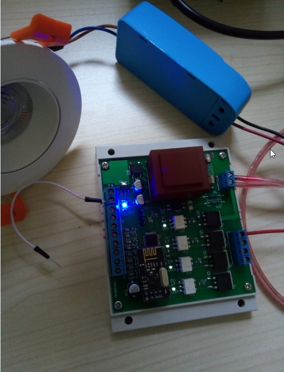
@HouseIOT As a newbie, I did a board completely following you schematics. But unfortunately,not working...
I use the MYsensores-bootloader(8Mhz,V1.5.4!), and I flashed your source ino-code into the board.
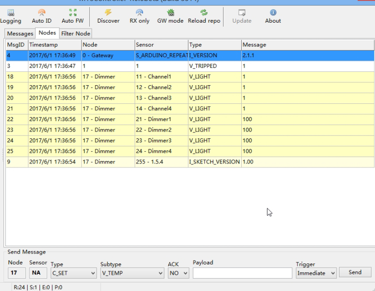
I can see the dimmer in the MYSController(as picture show), but there's no output from the X1.
My gateway is a esp8266 wifi gateway, version is 2.1.1 and it works fine.
PS: After testing job, the circuits of low voltage seems work well, shortcuts x5 and x2, the indicator led show lightness change(OFF, 30 & 100). The problem maybe in the Hi-voltage parts.
PLS help, THANKS a lot !
@hhalibo
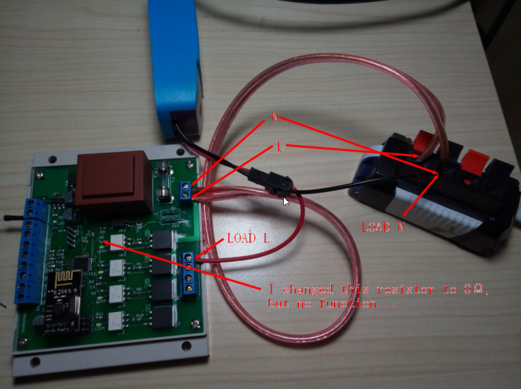
Check for neutral and phase connected right. I can see only one wire of load connected to X1. Other one must be connected to neutral if on X4.1 is phase. Otherwise try to reduce down to zero R5,7,9,11. May be not open the optocouplers. -
This post is deleted!
@Andrea-Boarino
Hi! It is Sanhe enclosure. I have bought it in Ukraine. -
@hhalibo
Check for neutral and phase connected right. I can see only one wire of load connected to X1. Other one must be connected to neutral if on X4.1 is phase. Otherwise try to reduce down to zero R5,7,9,11. May be not open the optocouplers. -
@HouseIOT THANKS for rapid reply!
I changed the resistor(r5) to 0 as pitcture shown, no function...
-
@hhalibo
What supply voltage? 3.3V?..
Usually if properly assembled, there should be no problems. -
@hhalibo
What supply voltage? 3.3V?..
Usually if properly assembled, there should be no problems. -
@hhalibo said in 💬 4-channel switcher/dimmer:
is 220v
My English not so good, sorry. I say about low voltage on Atmega. There should be not less than 3.3v. If it is less then may not be enough current to open the optocoupler.
D1 i not problem. The zero crossing detect works correctly. You see it on LEDs.
-
@hhalibo said in 💬 4-channel switcher/dimmer:
is 220v
My English not so good, sorry. I say about low voltage on Atmega. There should be not less than 3.3v. If it is less then may not be enough current to open the optocoupler.
D1 i not problem. The zero crossing detect works correctly. You see it on LEDs.
@HouseIOT The voltage output from the AMS1117-3.3 is 3.29v, and the voltage of the JP1 (VCC & GND) is 3.29v.
And when the V_PERCENTAGE is 100, the voltage input of the pin1&2 with OK2(3,4,5) is 0.825V.
when V_PERCENTAGE is 30, the voltage input of the pin1&2 with OK2(3,4,5) is 0.25V.
except the voltage input of OK(2,3,4,5) is definitely low,others seems OK.
-
@HouseIOT Sorry to trouble you, i use a mysensors-wifi-gateway with protocol 2.1.1 , and my homeautomation is home-assistant. I can't use your dimmer in my system.
After read the reference, there need to add V-percentage and V-status in the code, as a newbie , I can't do it myself. So I wondered,can you do me a favor?
Thanks a lot.