MySensors weather station
-
Some things about the direction sensor, your magnet/reed switch is exactly what is in the old dallas 1-wire weather station and it worked well giving 16 positions,
the led/photodiode method mentioed by gohan is interesting, if you used analog inputs you could use the value across 3 of them at a time to interpolate a pretty high resolution answer, multiplexing could make it so you dont need 8 analog inputs.
Another thing is a rotary encoder, ive seen them used to measure the angles of telescope mounts, i believe they can be had with good enough resolution for your needs.
I didnt read the whole thread, apologies if i am repeating ideas, or if you have decided on a solution.
@wallyllama No problem, I appreciate the input.
-
So for the phototransistor method, I figured I could use a similar approach to what I was planning with the reed switches. Here is a proposed schematic:
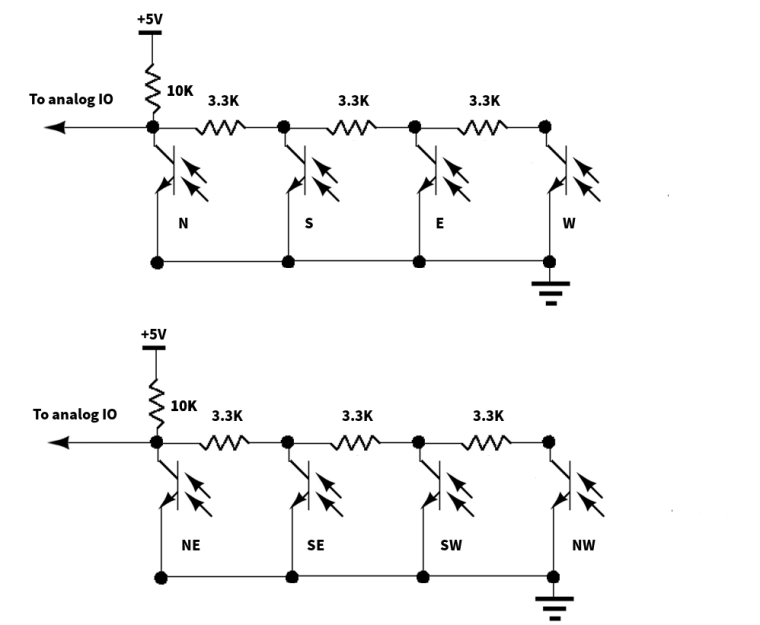
The idea is to use two identical banks of 4 phototransistors and alternating these in the slots. This should allow me to get the increased resolution that I was figuring on getting with the reed switch design.
Does anyone see any issues with this design?
-
So for the phototransistor method, I figured I could use a similar approach to what I was planning with the reed switches. Here is a proposed schematic:
The idea is to use two identical banks of 4 phototransistors and alternating these in the slots. This should allow me to get the increased resolution that I was figuring on getting with the reed switch design.
Does anyone see any issues with this design?
@dbemowsk
On my(fody) wind direction they use GND instead of VCC. When light is hitting the receiver, GND is passing through and you get a shortcut. I think, in that way you don't need all the 3,3K resistors.About resolution, personally I wouldn't focus on that because the wind is never in the same direction more than a few second then it moves a little bit. Maybe it stays in same direction when you have strong winds?
-
@dbemowsk
On my(fody) wind direction they use GND instead of VCC. When light is hitting the receiver, GND is passing through and you get a shortcut. I think, in that way you don't need all the 3,3K resistors.About resolution, personally I wouldn't focus on that because the wind is never in the same direction more than a few second then it moves a little bit. Maybe it stays in same direction when you have strong winds?
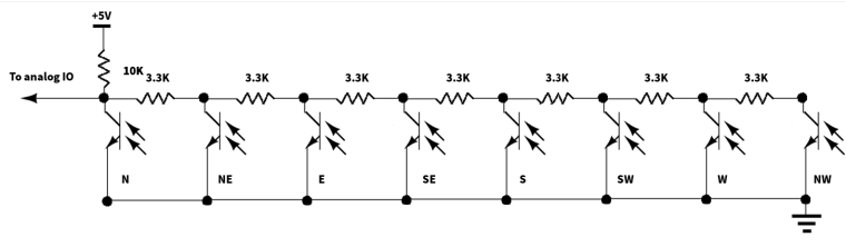
@flopp Are you only using 1 analog data line? The idea behind the resistors is to give varying degrees of 0 to 5 volts on the analog pin. Depending on which phototransistor is triggered, the value seen by the IO line is different for every one allowing you to differentiate which sensor is tripped.
If you are saying not to worry as much about the resolution, then I should be able to drop to using only 1 analog line instead of two with a configuration like this:
-
@dbemowsk
I am using 8 digital inputs, with pinmode(x,INPUT_PULLUP) on all of them, A0, A1 and A2 i use as digital input because I am using UNO so all the digitals was occupied with NRf and Rain, Wind speed.@flopp I just didn't want to use up all the IO lines if I didn't have to. The designs that I was showing with the resistors allows you to detect multiple switch triggers with 1 or 2 I/O lines depending how you want that detection done. I want to add a few other sensors to the setup, so I want to keep as many IO lines free as I can.
-
Just got my phototransistors. The ebay auction said that it was for 10 sensors. I got 15..... BONUS. :^)
-
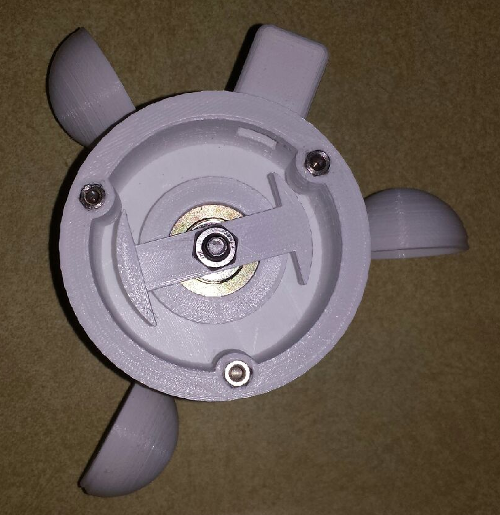
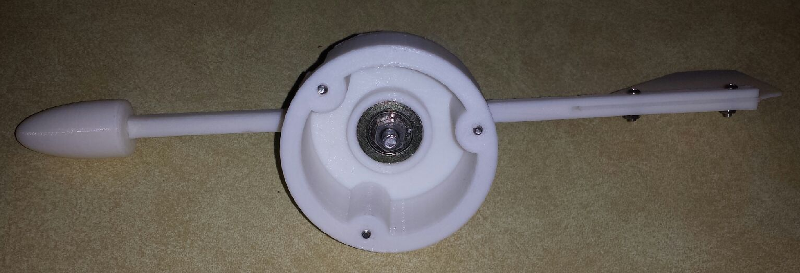
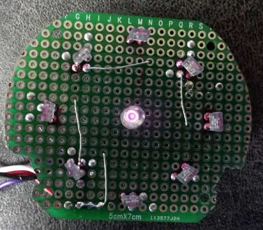
OK, so I am doing some testing on the new wind direction sensor board I am building. My problem is that the infrared LED that I have, which was scavanged from an old remote, has good IR pointing forward. but when I try to direct it sideways to the IR sensors, I appear to not be getting enough IR light to trigger the sensors. If I shine a flashlight at each of the sensors, they register, but not when O Does anyone know of either a different IR diode, or a way that I can get the existing diode to shine more in a sideways direction? Here is what the board is looking like. I currently only have one set of 4 sensors connected for testing. You can kind of see that the IR LED is lit.
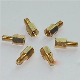
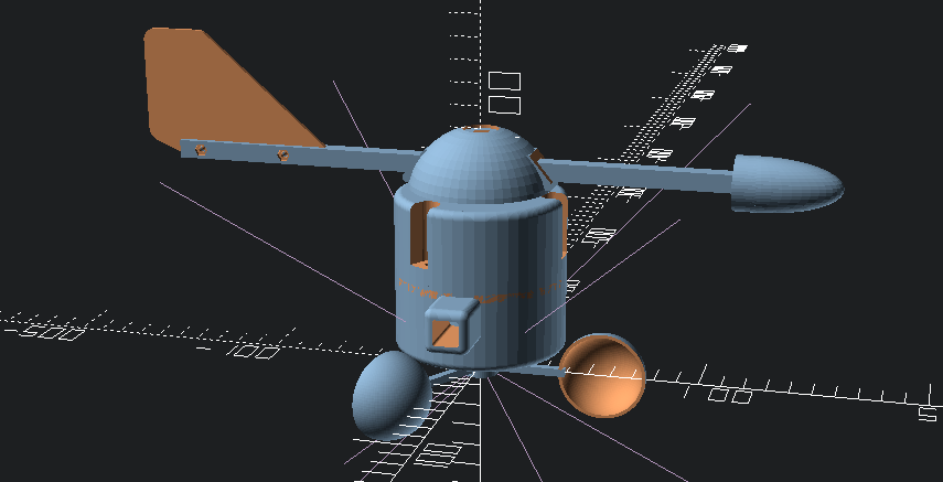
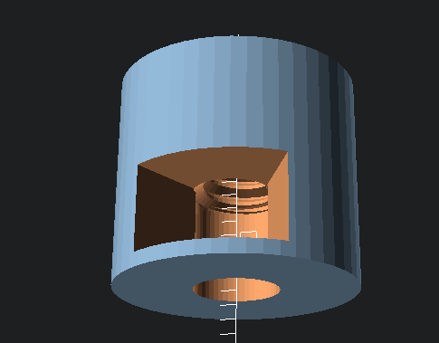
This is the design of the IR rotor that directs the light which gets screwed to the end of the bolt that is the shaft of the wind direction vane. The majority of the IR light gets directed at the end of the bolt.
 .
.I am up for any suggestions.
Vera Plus running UI7 with MySensors, Sonoffs and 1-Wire devices
Visit my website for more Bits, Bytes and Ramblings from me: http://dan.bemowski.info/ -
Just got my phototransistors. The ebay auction said that it was for 10 sensors. I got 15..... BONUS. :^)
-
OK, so I am doing some testing on the new wind direction sensor board I am building. My problem is that the infrared LED that I have, which was scavanged from an old remote, has good IR pointing forward. but when I try to direct it sideways to the IR sensors, I appear to not be getting enough IR light to trigger the sensors. If I shine a flashlight at each of the sensors, they register, but not when O Does anyone know of either a different IR diode, or a way that I can get the existing diode to shine more in a sideways direction? Here is what the board is looking like. I currently only have one set of 4 sensors connected for testing. You can kind of see that the IR LED is lit.
This is the design of the IR rotor that directs the light which gets screwed to the end of the bolt that is the shaft of the wind direction vane. The majority of the IR light gets directed at the end of the bolt.
.I am up for any suggestions.
@dbemowsk i have an led flashlight in the shape of a lantern, it has a shape like cone that has been dehydrated, so there is a concave curve from the base to the tip. Sort of like a golf tee but different proportions.
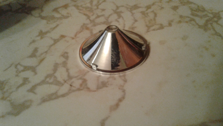
I guess it it like a regular flashlight reflector inside out
-
@dbemowsk 15 is metric for 10.*
- If you received 16, then I could have said you ordered in hex, and this would actually have been funny.
@wallyllama That would have been funny. There are 10 types of people in this world, Those that understand binary, and those that don't.
-
@dbemowsk i have an led flashlight in the shape of a lantern, it has a shape like cone that has been dehydrated, so there is a concave curve from the base to the tip. Sort of like a golf tee but different proportions.
I guess it it like a regular flashlight reflector inside out
@wallyllama My only problem with this is that the hole that the LED fits in is slightly larger than 5mm, so that cone would need to be tiny.
-
OK, so I am doing some testing on the new wind direction sensor board I am building. My problem is that the infrared LED that I have, which was scavanged from an old remote, has good IR pointing forward. but when I try to direct it sideways to the IR sensors, I appear to not be getting enough IR light to trigger the sensors. If I shine a flashlight at each of the sensors, they register, but not when O Does anyone know of either a different IR diode, or a way that I can get the existing diode to shine more in a sideways direction? Here is what the board is looking like. I currently only have one set of 4 sensors connected for testing. You can kind of see that the IR LED is lit.
This is the design of the IR rotor that directs the light which gets screwed to the end of the bolt that is the shaft of the wind direction vane. The majority of the IR light gets directed at the end of the bolt.
.I am up for any suggestions.
@dbemowsk actually, you only have to illuminate the sensors that your slot faces, a 45° mirror or a reflector opposite the slot should help.
-
Maybe a steel sphere? A white piece of plastic? Remember that you can use the smartphone camera to see the ir light coming from the led, in case you would like to see the result before assembling it
-
Hello all,
I'd like to add to this discussion my bit,
here is code from my older project of arduino based, battery operated, solar panel charged weather station
https://github.com/Luc3as/MySensors-WeatherStation
I must finish all documentation, I have PCBs ready and manufactured and tested, and models ready for 3d prints too.
I am not measuring wind so I am also interested in nice work above.
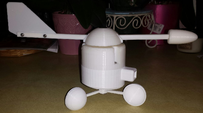
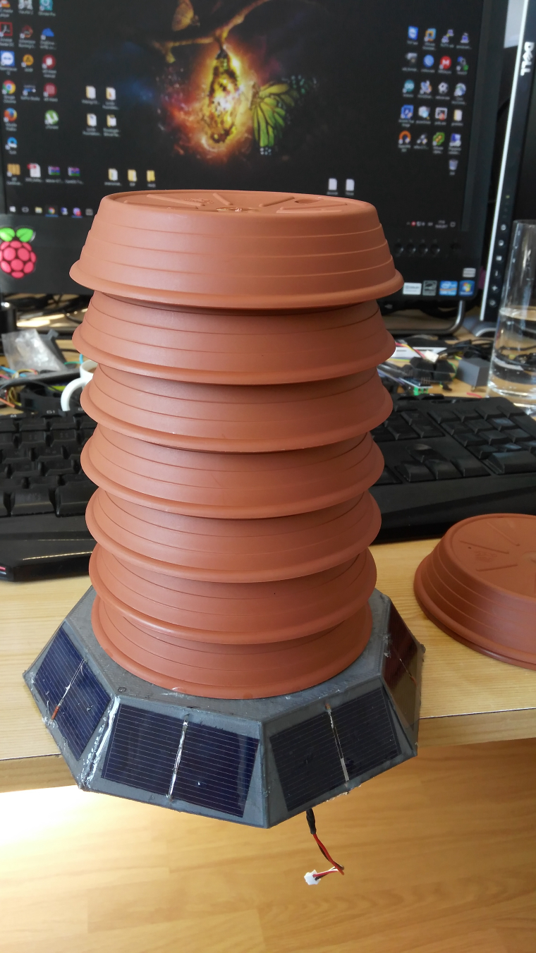
for now it is still work in progress, here is little teaser of overall look
-
Hello all,
I'd like to add to this discussion my bit,
here is code from my older project of arduino based, battery operated, solar panel charged weather station
https://github.com/Luc3as/MySensors-WeatherStation
I must finish all documentation, I have PCBs ready and manufactured and tested, and models ready for 3d prints too.
I am not measuring wind so I am also interested in nice work above.
for now it is still work in progress, here is little teaser of overall look
@Luc3as Thanks for the contribution. I have been quite busy the past few weeks and haven't had a lot of time to work more on the wind direction sensor. There are still a few issues I am working through with that before I can start jumping into the code for it. I am hoping to get more done this weekend.
As for your 3D files, do you have them on thingiverse or somewhere accessible for us to check them out? I am interested in the work you have done.