RGB LED strip

-
@maghac @moskovskiy82 I came across this some time ago, with an RGB LED project. Whilst I can't recall the details, it's to do with setting the Arduino's PWM timers - apparently, the frequencies of the R(ed) & B(lue) channels can be close enough to causing 'beating', which gives rise to flickering. This statement changes the frequency of one of the channels slightly, thereby eliminating the flickering.
Yes, after googling it I could see it was related to setting the timers. There is maybe another way to fix it and still keep the correct timer functions for other functionalities to be intact (e.g so that @moskovskiy82 can still use the DHT22), but I haven't investigated further. In any case, I believe it's easier to split separate functions to separate physical units instead of trying to put as much functionality into one single unit as possible.
In my case, the unit is mounted in a not-so-well-ventilated enclosure in the ceiling, so I doubt that I would get a correct temperature reading anyway :)
-
@OliverDog HA will not send VAR1 or VAR2 unless you implement some specific functionality to do this. I set up switches in HA to send the correct MQTT message to the mysensors gateway in order to activate the alarm and relax modes. Here's my switch.yaml file:
- platform: tellstick - platform: mqtt name: "Alarm" command_topic: "mysensors-in/3/1/1/0/25" payload_on: "1" payload_off: "0" optimistic: false qos: 0 retain: false - platform: mqtt name: "Relax" command_topic: "mysensors-in/3/1/1/0/25" payload_on: "2" payload_off: "0" optimistic: false qos: 0 retain: false@maghac I have posted the issue (not working VAR1 and VAR2 on Home Assistant) on the HA forum, and got steps for asking the implement...
I will ask for such implement and it may work later...
Thanks for the help...By the way, I did not test the switches but seems doing the job...
-
After some investigating it wasn't a timer issue but a range issue with a node (it was hard to figure out). So went ahead and built another node with your code. But being lazy - just bought an rgb strip drive from aliexpress (too much soldering of mosfets for me).
It uses some RGBdriver.h library https://github.com/letsgoING/Libraries/tree/master/LEDStripDriver
fe
All i had to change wasvoid set_rgb(int r, int g, int b) { Driver.begin(); Driver.SetColor(r, g, b); Driver.end(); }And it worked. Except that fading/RELAX don't work out for me. Instead just get a flashing of white light. So i thought you might know some other parts must be adjusted as my arduino knowledge is not there yer
-
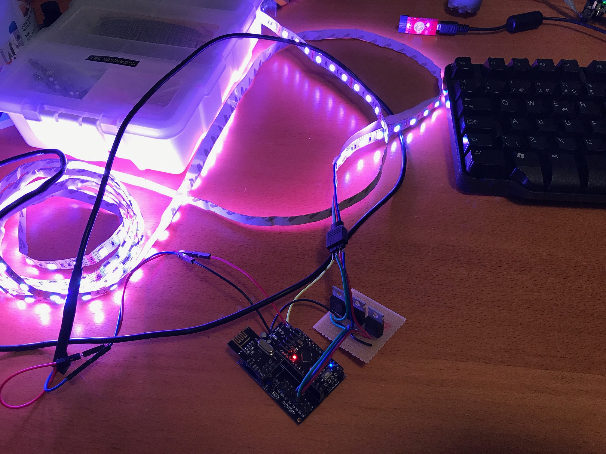
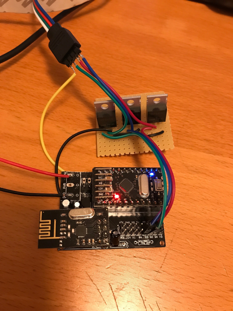
I built a RGB LED strip controllable via mysensor, based on a 12V RGB LED strip and three IRF540 MOSFETs. The arduino is a 5V pro mini clone that I feed with 12V on the RAW pin.
I followed the guide on https://learn.adafruit.com/rgb-led-strips/usage for wiring the MOSFETS and the LED strip. I used the Newbie PCB by @sundberg84 for holding the arduino and the radio, but put the MOSFETs on a separate prototyping board (maybe next time I'll try to solder them to the prototyping area of the Newbie PCB).
I implemented a fading feature in the sketch, so it can fade slowly between colors or on/off. The speed is controlled by sending a V_VAR1 message with the speed (typical value could be around 200-300 for a nice effect). Speed = 0 means fading is off.
Here is the code:
/**
 * This program is free software; you can redistribute it and/or
 * modify it under the terms of the GNU General Public License
 * version 2 as published by the Free Software Foundation.
 *
 * LED STRIP sketch for Mysensors
 *******************************
 *
 * REVISION HISTORY
 * 1.0
 *   Based on the example sketch in mysensors
 * 1.1
 *   fadespeed parameter (send as V_VAR1 message)
 *   HomeAssistant compatible (send status to ack)
 */

#define MY_OTA_FIRMWARE_FEATURE
#define MY_NODE_ID AUTO

#define MY_RADIO_NRF24

#include <MySensors.h>

#define CHILD_ID_LIGHT 1

#define SN "LED Strip"
#define SV "1.1"

MyMessage lightMsg(CHILD_ID_LIGHT, V_LIGHT);
MyMessage rgbMsg(CHILD_ID_LIGHT, V_RGB);
MyMessage dimmerMsg(CHILD_ID_LIGHT, V_DIMMER);

byte red = 255;
byte green = 255;
byte blue = 255;
byte r0 = 255;
byte g0 = 255;
byte b0 = 255;
char rgbstring[] = "ffffff";

int on_off_status = 0;
int dimmerlevel = 100;
int fadespeed = 0;

#define REDPIN 6
#define GREENPIN 5
#define BLUEPIN 3

void setup()
{
  // Fix the PWM timer. Without this the LEDs will flicker.
  TCCR0A = _BV(COM0A1) | _BV(COM0B1) | _BV(WGM00);

  // Output pins
  pinMode(REDPIN, OUTPUT);
  pinMode(GREENPIN, OUTPUT);
  pinMode(BLUEPIN, OUTPUT);

}

void presentation()
{
	// Send the Sketch Version Information to the Gateway
	sendSketchInfo(SN, SV);
	present(CHILD_ID_LIGHT, S_RGB_LIGHT);
}

void loop()
{
  static bool first_message_sent = false;
  if ( first_message_sent == false ) {
    Serial.println( "Sending initial state..." );
    set_hw_status();
    send_status();
    first_message_sent = true;
  }
}

void receive(const MyMessage &message)
{
  int val;

	if (message.type == V_RGB) {
		Serial.println( "V_RGB command: " );
    Serial.println(message.data);
    long number = (long) strtol( message.data, NULL, 16);

    // Save old value
    strcpy(rgbstring, message.data);

    // Split it up into r, g, b values
    red = number >> 16;
    green = number >> 8 & 0xFF;
    blue = number & 0xFF;

    send_status();
    set_hw_status();

	} else if (message.type == V_LIGHT || message.type == V_STATUS) {
    Serial.println( "V_LIGHT command: " );
    Serial.println(message.data);
    val = atoi(message.data);
    if (val == 0 or val == 1) {
      on_off_status = val;
      send_status();
      set_hw_status();
    }

  } else if (message.type == V_DIMMER || message.type == V_PERCENTAGE) {
    Serial.print( "V_DIMMER command: " );
    Serial.println(message.data);
    val = atoi(message.data);
    if (val >= 0 and val <=100) {
      dimmerlevel = val;
      send_status();
      set_hw_status();
    }

  } else if (message.type == V_VAR1 ) {
    Serial.print( "V_VAR1 command: " );
    Serial.println(message.data);
    val = atoi(message.data);
    if (val >= 0 and val <= 2000) {
      fadespeed = val;
    }

	} else {
		Serial.println( "Invalid command received..." );
		return;
	}

}

void set_rgb(int r, int g, int b) {
  analogWrite(REDPIN, r);
  analogWrite(GREENPIN, g);
  analogWrite(BLUEPIN, b);
}

void set_hw_status() {
  int r = on_off_status * (int)(red * dimmerlevel/100.0);
  int g = on_off_status * (int)(green * dimmerlevel/100.0);
  int b = on_off_status * (int)(blue * dimmerlevel/100.0);

  if (fadespeed >0) {

    float dr = (r - r0) / float(fadespeed);
    float db = (b - b0) / float(fadespeed);
    float dg = (g - g0) / float(fadespeed);

    for (int x = 0;  x < fadespeed; x++) {
      set_rgb(r0 + dr*x, g0 + dg*x, b0 + db*x);
      delay(100);
    }
  }

  set_rgb(r, g, b);

  r0 = r;
  b0 = b;
  g0 = g;

}


void send_status() {
  send(rgbMsg.set(rgbstring));
  send(lightMsg.set(on_off_status));
  send(dimmerMsg.set(dimmerlevel));
}
I have a MQTT gateway and I can turn the strip on, set the color to pink and fade speed to 500 by the following commands:
mosquitto_pub -t mysensors-in/240/1/1/0/40 -m ff6060
mosquitto_pub -t mysensors-in/240/1/1/0/24 -m 500
mosquitto_pub -t mysensors-in/240/1/1/0/2 -m 1
A couple of pics:

-
@DrJeff That's the Newbie PCB by @sundberg84 (https://www.mysensors.org/hardware/newbie-pcb)
-
@DrJeff That's the Newbie PCB by @sundberg84 (https://www.mysensors.org/hardware/newbie-pcb)
-
@maghac Oh yes by the way the code above works great just added some code for Motion sensor and Now I have a much better light.
/** * This program is free software; you can redistribute it and/or * modify it under the terms of the GNU General Public License * version 2 as published by the Free Software Foundation. * * LED STRIP sketch for Mysensors ******************************* * * REVISION HISTORY * 1.0 * Based on the example sketch in mysensors * 1.1 * fadespeed parameter (send as V_VAR1 message) * HomeAssistant compatible (send status to ack) * 1.2 * OTA support * 1.3 * Power-on self test * 1.4 * Bug fix * 1.5 * Other default values * 1.6 * Repeater feature * 1.7 * Multitasking. Alarm, Relax and normal modes. */ #define MY_OTA_FIRMWARE_FEATURE #define MY_REPEATER_FEATURE #define MY_NODE_ID 31 // added all the motion stuff DrJeff September 10, 2017 #define MOTION_1 3 // The digital input you attached your motion sensor. (Only 2 and 3 generates interrupt!) #define MOTION_ID 90 // Id of the sensor child uint8_t lastMotion_1 = 0; unsigned long previousMillis1 = 0; unsigned long motionDelay1 = 10000; // interval at which to keep motion sensor trippped (milliseconds). Used to prevent too frequent updates to Vera. /// #define MY_RADIO_NRF24 #define MY_DEBUG #include <MySensors.h> #define CHILD_ID_LIGHT 1 #define SN "LED Strip" #define SV "1.7" MyMessage lightMsg(CHILD_ID_LIGHT, V_LIGHT); MyMessage rgbMsg(CHILD_ID_LIGHT, V_RGB); MyMessage dimmerMsg(CHILD_ID_LIGHT, V_DIMMER); // added all the motion stuff DrJeff September 10, 2017 MyMessage motion(MOTION_ID, V_TRIPPED); // int current_r = 255; int current_g = 255; int current_b = 255; int target_r = 255; int target_g = 255; int target_b = 255; int save_r; int save_g; int save_b; float delta_r = 0.0; float delta_g = 0.0; float delta_b = 0.0; char rgbstring[] = "ffffff"; int on_off_status = 0; int dimmerlevel = 100; int fadespeed = 20; unsigned long last_update = 0; int tick_length = 10; int fade_step = 0; int program_timer; int program_cycle; #define REDPIN 6 #define GREENPIN 4 #define BLUEPIN 5 #define LIGHT_NORMAL 0 #define LIGHT_FADING 1 #define PROGRAM_NORMAL 0 #define PROGRAM_ALARM 1 #define PROGRAM_RELAX 2 int light_mode = LIGHT_NORMAL; int program_mode = PROGRAM_NORMAL; #define RELAX_SPEED 50 #define MAX_CYCLES_RELAX 7 const int program_param_RELAX[MAX_CYCLES_RELAX][3] = { {255, 32, 0}, {255, 32, 16}, {255, 16, 32}, {255, 128, 0}, {255, 32, 00}, {255, 32, 32}, {255, 0, 32} }; void setup() { // Fix the PWM timer. Without this the LEDs will flicker. TCCR0A = _BV(COM0A1) | _BV(COM0B1) | _BV(WGM00); // Output pins pinMode(REDPIN, OUTPUT); pinMode(GREENPIN, OUTPUT); pinMode(BLUEPIN, OUTPUT); // added all the motion stuff DrJeff September 10, 2017 pinMode(MOTION_1, INPUT); // } void presentation() { // Send the Sketch Version Information to the Gateway sendSketchInfo(SN, SV); present(CHILD_ID_LIGHT, S_RGB_LIGHT); // added all the motion stuff DrJeff September 10, 2017 present(MOTION_ID, S_MOTION); // } void selftest() { on_off_status = 1; current_r = 255; current_g = 0; current_b = 0; set_hw_status(); wait(100); current_r = 0; current_g = 255; set_hw_status(); wait(100); current_g = 0; current_b = 255; set_hw_status(); wait(100); current_r = 255; current_g = 255; set_hw_status(); wait(100); on_off_status = 0; } void loop() { static bool first_message_sent = false; if ( first_message_sent == false ) { selftest(); set_hw_status(); send_status(1, 1, 1); first_message_sent = true; } // added all the motion stuff DrJeff September 10, 2017//loop for motion unsigned long currentMillis = millis(); if(currentMillis - previousMillis1 > motionDelay1) { uint8_t motionDetect1 = digitalRead(MOTION_1); if(motionDetect1 != lastMotion_1) { Serial.print("Motion 1 = "); Serial.println(motionDetect1); // gw.send(motionStatus_1.set(motionDetect1 ? "1" : "0")); // Send tripped value to gw send(motion.set(motionDetect1)); if(motionDetect1 == 1) { previousMillis1 = currentMillis; //"Tripped" delay } else { previousMillis1 = currentMillis - motionDelay1 + 1000; //"Not tripped" delay for 1 second to stop rapid "not tripped" and "tripped" updates to Vera } lastMotion_1 = motionDetect1; } } //end of motion loop unsigned long now = millis(); if (now - last_update > tick_length) { last_update = now; if (light_mode == LIGHT_FADING) { calc_fade(); } if (program_mode > PROGRAM_NORMAL) { handle_program(); } } set_hw_status(); } void receive(const MyMessage &message) { int val; if (message.type == V_RGB) { Serial.print( "V_RGB: " ); Serial.println(message.data); long number = (long) strtol( message.data, NULL, 16); // Save old value strcpy(rgbstring, message.data); // Split it up into r, g, b values int r = number >> 16; int g = number >> 8 & 0xFF; int b = number & 0xFF; init_fade(fadespeed, r, g, b); send_status(0, 0, 1); } else if (message.type == V_LIGHT || message.type == V_STATUS) { Serial.print( "V_LIGHT: " ); Serial.println(message.data); val = atoi(message.data); if (val == 0 or val == 1) { on_off_status = val; send_status(1, 0, 0); } } else if (message.type == V_DIMMER || message.type == V_PERCENTAGE) { Serial.print( "V_DIMMER: " ); Serial.println(message.data); val = atoi(message.data); if (val >= 0 and val <=100) { dimmerlevel = val; send_status(0, 1, 0); } } else if (message.type == V_VAR1 ) { Serial.print( "V_VAR1: " ); Serial.println(message.data); val = atoi(message.data); if (val >= 0 and val <= 2000) { fadespeed = val; } } else if (message.type == V_VAR2 ) { Serial.print( "V_VAR2: " ); Serial.println(message.data); val = atoi(message.data); if (val == PROGRAM_NORMAL) { stop_program(); } else if (val == PROGRAM_ALARM || val == PROGRAM_RELAX) { init_program(val); } } else { Serial.println( "Invalid command received..." ); return; } } void set_rgb(int r, int g, int b) { analogWrite(REDPIN, r); analogWrite(GREENPIN, g); analogWrite(BLUEPIN, b); } void init_program(int program) { program_mode = program; program_cycle = 0; save_rgb(); if (program == PROGRAM_ALARM) { light_mode = LIGHT_NORMAL; current_r = 255; current_g = 255; current_b = 255; program_timer = 50; } else if (program == PROGRAM_RELAX) { program_timer = 300; init_fade(fadespeed, program_param_RELAX[program_cycle][0], program_param_RELAX[program_cycle][1], program_param_RELAX[program_cycle][2]); } } void handle_program() { program_timer--; if (program_mode == PROGRAM_ALARM) { if (program_timer == 0) { program_timer = 50; if (program_cycle == 0) { program_cycle = 1; current_r = 0; current_g = 0; current_b = 0; } else { program_cycle = 0; current_r = 255; current_g = 255; current_b = 255; } } } else if (program_mode == PROGRAM_RELAX) { if (light_mode == LIGHT_NORMAL) { program_cycle = (program_cycle+1) % MAX_CYCLES_RELAX; Serial.print("Next cycle step "); Serial.println(program_cycle); init_fade(fadespeed * RELAX_SPEED, program_param_RELAX[program_cycle][0], program_param_RELAX[program_cycle][1], program_param_RELAX[program_cycle][2]); } } } void stop_program() { restore_rgb(); light_mode = LIGHT_NORMAL; program_mode = PROGRAM_NORMAL; } void save_rgb() { save_r = current_r; save_g = current_g; save_b = current_b; } void restore_rgb() { current_r = save_r; current_g = save_g; current_b = save_b; } void init_fade(int t, int r, int g, int b) { Serial.print( "Init fade" ); light_mode = LIGHT_FADING; target_r = r; target_g = g; target_b = b; fade_step = t; delta_r = (target_r - current_r) / float(fade_step); delta_g = (target_g - current_g) / float(fade_step); delta_b = (target_b - current_b) / float(fade_step); } void calc_fade() { if (fade_step > 0) { fade_step--; current_r = target_r - delta_r * fade_step; current_g = target_g - delta_g * fade_step; current_b = target_b - delta_b * fade_step; } else { Serial.println( "Normal mode" ); light_mode = LIGHT_NORMAL; } } void set_hw_status() { int r = on_off_status * (int)(current_r * dimmerlevel/100.0); int g = on_off_status * (int)(current_g * dimmerlevel/100.0); int b = on_off_status * (int)(current_b * dimmerlevel/100.0); set_rgb(r, g, b); } void send_status(int send_on_off_status, int send_dimmerlevel, int send_rgbstring) { if (send_rgbstring) send(rgbMsg.set(rgbstring)); if (send_on_off_status) send(lightMsg.set(on_off_status)); if (send_dimmerlevel) send(dimmerMsg.set(dimmerlevel)); } -
Hey @maghac - just wondering how you got the 12V to your fitting? have you got a transformer in the ceiling above ? Regards, mick
-
@mick said in RGB LED strip:
@maghac Thanks for the reply, mate. The light looks great mounted up - very impressed!
Thanks! The "relax" program is actually quite nice since it changes colours so slowly so it takes a while before you notice it. A great way to impress your dinner guests :)
-
I dont know what went wrong, but RED is just always on. Yesterday in the breadboard it was ok. Today in the breadboard red was on. So i thought lets just solder it... Now I soldered it to a pcb, RED on all the time. This must be a ground issue, but where do i look?
It is even red when just all the connections are off, 12v to raw and strip, then connect ground to arduino, BOOM red comes on...
-
@xypzo Double check your connections, perhaps you're connecting to the wrong pin on the arduino? If you swap red and green, what happens then?
@maghac said in RGB LED strip:
your connections, perhaps you're connecting to the wrong pin on the arduino
Then green keeps on, so it should be a pin 6 problem, but i can't find it. Maybe I try a 10kohm resistor between gate and ground... Or IRFZ instead of IRLZ transistors.
BTW, bought a LD362A ufo which works great with my controller, but i still want to win this battle!
-
@maghac said in RGB LED strip:
your connections, perhaps you're connecting to the wrong pin on the arduino
Then green keeps on, so it should be a pin 6 problem, but i can't find it. Maybe I try a 10kohm resistor between gate and ground... Or IRFZ instead of IRLZ transistors.
BTW, bought a LD362A ufo which works great with my controller, but i still want to win this battle!
@xypzo said in RGB LED strip:
@maghac said in RGB LED strip:
your connections, perhaps you're connecting to the wrong pin on the arduino
Then green keeps on, so it should be a pin 6 problem, but i can't find it. Maybe I try a 10kohm resistor between gate and ground... Or IRFZ instead of IRLZ transistors.
BTW, bought a LD362A ufo which works great with my controller, but i still want to win this battle!
You could try to use a different pin. Can't remember off the top of my head which pins are PWM capable though.
I've had a couple of cheap arduino clones where some of the pins were not correctly soldered.
-
@maghac The stupid thing, is that the day before, same setup, no red lights stayed on. It happened overnight!!! Maybe the mice did it! :')
-
Hi!
I'm doing some further development based on the sketch by @maghac and @DrJeff above and I have found two potential bugs that could create some unexpected behaviour.
The first is that if you have #DEFINE RELAX_SPEED 50 in the sketch and then set fadespeed (V_VAR1) to anything greater than 650 or so, you will get an overflow when you call the function init_fade (t, r, g, b ) since t is defined as int in init_fade.
fadespeed can be set between 0 and 2000 in the sketch. So then the resulting fadespeed could be anything, even negative.init_fade(fadespeed * RELAX_SPEED, program_param_RELAX[program_cycle][0], program_param_RELAX[program_cycle][1], program_param_RELAX[program_cycle][2]);Also in this function there is a potential risk of a "divide by zero" crash since the input variable t is used as fade_step to divide in order to get the size of each step in the fade cycle.
void init_fade(int t, int r, int g, int b) {
  Serial.print( "Init fade" );
  light_mode = LIGHT_FADING;
  target_r = r;
  target_g = g;
  target_b = b;
  fade_step = t;
  delta_r = (target_r - current_r) / float(fade_step);
  delta_g = (target_g - current_g) / float(fade_step);
  delta_b = (target_b - current_b) / float(fade_step);
}
It might be that this function is never called with fadestep = t = 0 but since this is a value allowed in the input check of V_VAR1 nasty things may happen.
Part from this I am impressed by the sketch. Once I have debugged my own additions I will post the project here.I have never been so busy since I retired!
-
Hi!
I'm doing some further development based on the sketch by @maghac and @DrJeff above and I have found two potential bugs that could create some unexpected behaviour.
The first is that if you have #DEFINE RELAX_SPEED 50 in the sketch and then set fadespeed (V_VAR1) to anything greater than 650 or so, you will get an overflow when you call the function init_fade (t, r, g, b ) since t is defined as int in init_fade.
fadespeed can be set between 0 and 2000 in the sketch. So then the resulting fadespeed could be anything, even negative.init_fade(fadespeed * RELAX_SPEED, program_param_RELAX[program_cycle][0], program_param_RELAX[program_cycle][1], program_param_RELAX[program_cycle][2]);Also in this function there is a potential risk of a "divide by zero" crash since the input variable t is used as fade_step to divide in order to get the size of each step in the fade cycle.
void init_fade(int t, int r, int g, int b) {
  Serial.print( "Init fade" );
  light_mode = LIGHT_FADING;
  target_r = r;
  target_g = g;
  target_b = b;
  fade_step = t;
  delta_r = (target_r - current_r) / float(fade_step);
  delta_g = (target_g - current_g) / float(fade_step);
  delta_b = (target_b - current_b) / float(fade_step);
}
It might be that this function is never called with fadestep = t = 0 but since this is a value allowed in the input check of V_VAR1 nasty things may happen.
Part from this I am impressed by the sketch. Once I have debugged my own additions I will post the project here.@bgunnarb Thanks. As program space is limited, I chose not to put too much effort in input data validation, instead relying on the controller to not submit incorrect values. Maybe a quick range check would not waste so many bytes though.
Right now I am however experiencing some strange behavior - I can turn the the lamp on and off and I can dim it, but I cannot change the color of the strip. Also, the RELAX program does not work but the ALARM program works fine. So there are some other bugs that need to be ironed out :)