💬 Easy/Newbie PCB (RFM69 HW/W edition) for MySensors
-
@gohan - looking better on that SMA connector...
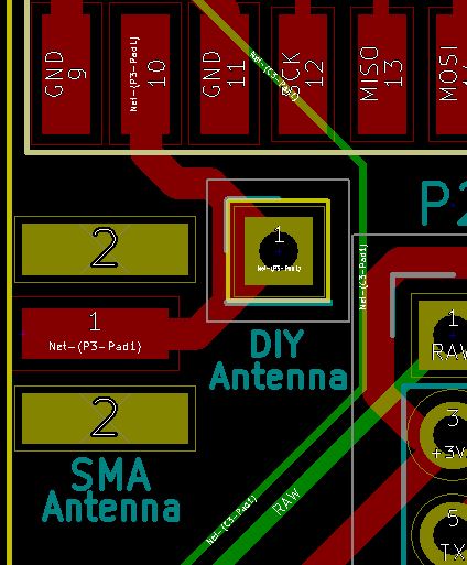
Anyone knows if its possible to have a SMA and Hole for DIY antenna on the same PCB like this?
Edit:
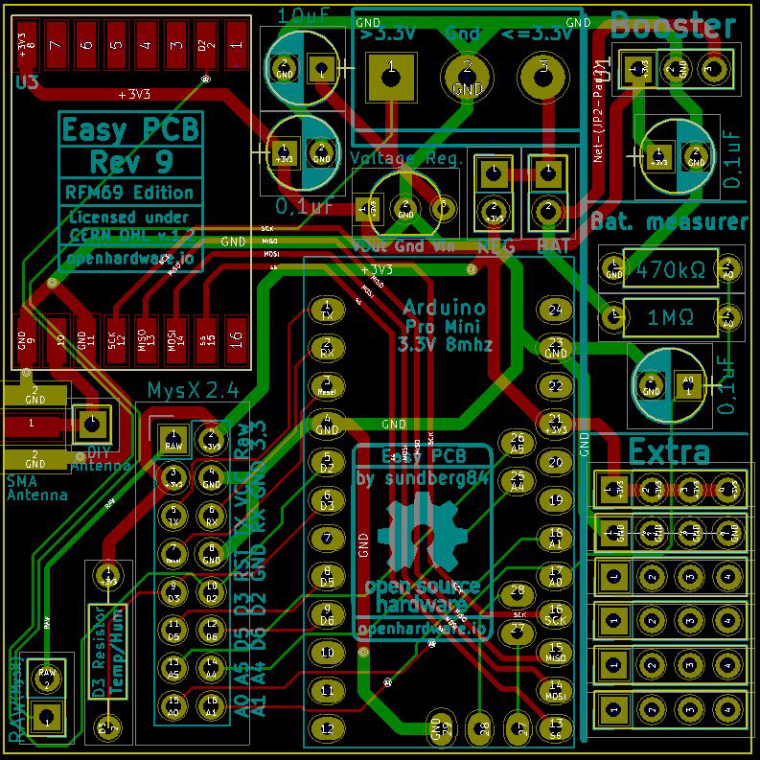
Well, so far tonight... a couple of hours work and im happy :) some small stuff to fix before production.
@sundberg84 I did this in my take of a SMA with a wire Antenna option:
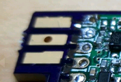 , you can see more details here https://www.openhardware.io/view/388/RFM69HW-Arduino-Mini-Pro-Shield.
Haven't tried with the wire antenna trough. -
@sundberg84 I did this in my take of a SMA with a wire Antenna option:
, you can see more details here https://www.openhardware.io/view/388/RFM69HW-Arduino-Mini-Pro-Shield.
Haven't tried with the wire antenna trough. -
This post is deleted!
-
So, this temporary GW is now connected to Domoticz and running at 34800 baud rate (had some problems to figure this out...) I have one (fake) node connected but still have some range issues to sort out. Most likley because of the DIY antenna...
-
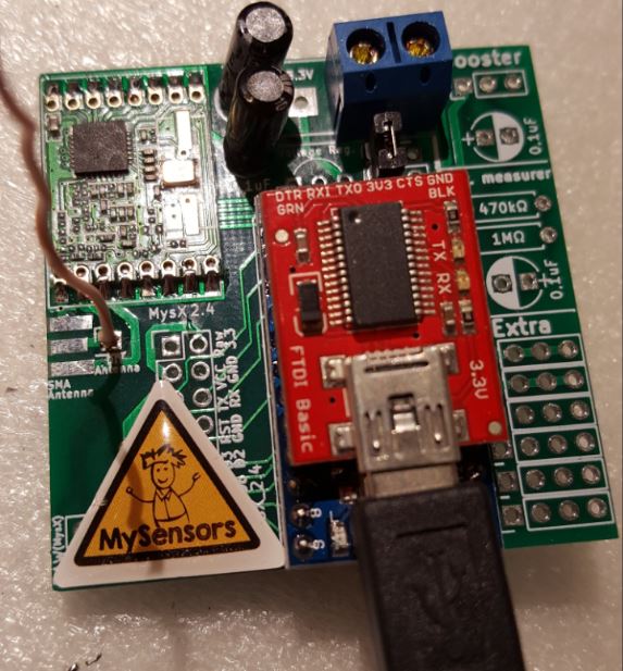
I now have a gw and node working together on 3.3v and 433mhz (not HW version). I would say its quite safe to order the PCB if someone wants to try it out.
Note to myself and others... the RFM69 is really sensitive to high power. I fried one because I tried it on a Nano which i think is using 5v on its gpio. I was just thinking... hmm 3.3v - nano got one of those!
-
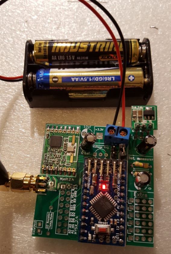
And now I also have a batterynode working... Power consumtion will come later... it works atleast :)
Someone that can guess what kind of power consumtion this setup would be (removing LED / regulator)?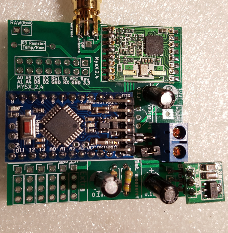
-
I now have a gw and node working together on 3.3v and 433mhz (not HW version). I would say its quite safe to order the PCB if someone wants to try it out.
Note to myself and others... the RFM69 is really sensitive to high power. I fried one because I tried it on a Nano which i think is using 5v on its gpio. I was just thinking... hmm 3.3v - nano got one of those!
@sundberg84 said in 💬 Easy/Newbie PCB (RFM69 HW/W edition) for MySensors:
I now have a gw and node working together on 3.3v and 433mhz (not HW version). I would say its quite safe to order the PCB if someone wants to try it out.
Note to myself and others... the RFM69 is really sensitive to high power. I fried one because I tried it on a Nano which i think is using 5v on its gpio. I was just thinking... hmm 3.3v - nano got one of those!
It's in datasheet that it is not 5v tolerant and absolute max voltage it's like 3.6v
-
@sundberg84 said in 💬 Easy/Newbie PCB (RFM69 HW/W edition) for MySensors:
I now have a gw and node working together on 3.3v and 433mhz (not HW version). I would say its quite safe to order the PCB if someone wants to try it out.
Note to myself and others... the RFM69 is really sensitive to high power. I fried one because I tried it on a Nano which i think is using 5v on its gpio. I was just thinking... hmm 3.3v - nano got one of those!
It's in datasheet that it is not 5v tolerant and absolute max voltage it's like 3.6v
@gohan - I was fooled by that the Nano got a 3.3v output... stupid.
-
So I have made the adjustment for low power/battery mode (removed the LED, voltage regulator and sleeping most of the time).
Im having a hard time to trust my Multimeter at this point... showing 5.1uA in sleep() mode while sending shows almost 2mA! This cant be right???
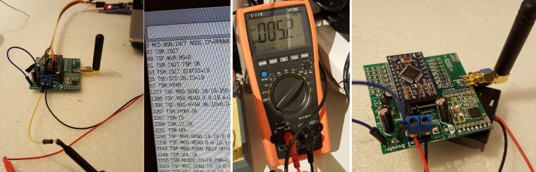
At the moment im all out of boosters... I was sure I had more so I didnt order.
What I have done now is uploaded a sketch sleeping 15min, running the vcc check (since I dont have a booster) and reporting it back to me. Lets see what happens...
-
To answer my own question I found this thread where he gets the exact same sleep current as I do (5.2uA). Still wondering about the high send current though.
Is 2.0mA a normal power consumption for RFM69W when its transmitting? Will investigate but all input appreciated...
-
To answer my own question I found this thread where he gets the exact same sleep current as I do (5.2uA). Still wondering about the high send current though.
Is 2.0mA a normal power consumption for RFM69W when its transmitting? Will investigate but all input appreciated...
-
@sundberg84 no. It should consume 16-45 mA. See datasheet.
@mfalkvidd - thanks. Have to recheck... maybe 2mA was during loop and there was a peak up which I didnt notice when transmitting. * feeling a bit more confident *
-
Hello,
Very nice job (as usual).
I think the first version was produced with Eagle. Can you post the Eagle version of the schematics and pcb ?
Thank you.Qq.
-
Hello,
Very nice job (as usual).
I think the first version was produced with Eagle. Can you post the Eagle version of the schematics and pcb ?
Thank you.Qq.
@qqlapraline - Hi!
Only the nrf24l01+ edition is made with Eagles. I used to make everything there but have moved to kicad now. The RFM69 edition is only made in Kicad only - sorry. -
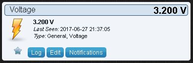
Update on the batterystatus as well while i write here. The node is still going strong at 3.2V so 5uA in sleep seems to be correct. I would say the battery function is working as well as expected so in all the major functions of this PCB is tested and passed!
-
Everything is going fine so im taking this to the next level... from test to produktion.
This sensor might be my most important summer sensor from now on ;)
A couple of days ago I had some friends over which gave me a beer cooler, garden edition.
Its pretty much a barrel in the ground which cools the beer down... (a bit atleast).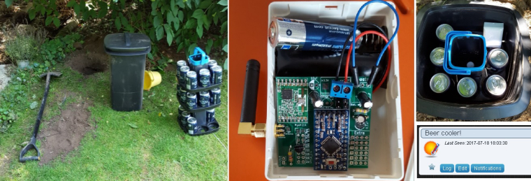
I must say Im very impressed with the RFM69 so far... except the price, there has been no trouble at all. No repeaters, no capacitors, no fine tuning... nothing. Pretty much solder 'n' play!
This node is burried in the far end on the garden (25m) and has to penetrate 3 concrete + 1brick wall to reach the GW in the celler... no problems, first try and bang!
So far... the temperature in the cooler isnt very impressive, and I have only tried the first layer. I was afraid I would loose radio coverage if I put the sensors far down... but I will try.
Cheers mates!
-
just add another sensor with a wire to reach the bottom of the barrel and you can see the temperature difference :)
@gohan - doh! Thats great... but no sport when you are testing the limits on the radio ;)
Hello! It looks like you're interested in this conversation, but you don't have an account yet.
Getting fed up of having to scroll through the same posts each visit? When you register for an account, you'll always come back to exactly where you were before, and choose to be notified of new replies (either via email, or push notification). You'll also be able to save bookmarks and upvote posts to show your appreciation to other community members.
With your input, this post could be even better 💗
Register Login