
Mosfet with Ceech board
-
Hello,
I would like to use the mosfet of the Ceech board: ATmega328p board w/ NRF24l01+ socket LTC4079
In the doc is indicated that it is wired do digital 3.
I have modified the "blink without delay" sketchconst int MOSFET = 3; int loadState = LOW; unsigned long previousMillis = 0; const long interval = 2000; void setup() { // put your setup code here, to run once: pinMode(MOSFET, OUTPUT); digitalWrite(MOSFET, HIGH); Serial.begin(9600); } void loop() { unsigned long currentMillis = millis(); if (currentMillis - previousMillis >= interval) { // save the last time you blinked the LED previousMillis = currentMillis; // if the LED is off turn it on and vice-versa: if (loadState == LOW) { loadState = HIGH; } else { loadState = 0; } // set the LED with the ledState of the variable: digitalWrite(MOSFET, loadState); Serial.print("state: ");Serial.println(loadState); } }I don't understand how it works, I have tried to measure continuity with a voltmeter, I have tried to wire a led between vcc, cuting the gnd with the mosfet without success.
Does anyone would be explain how I can use it ?
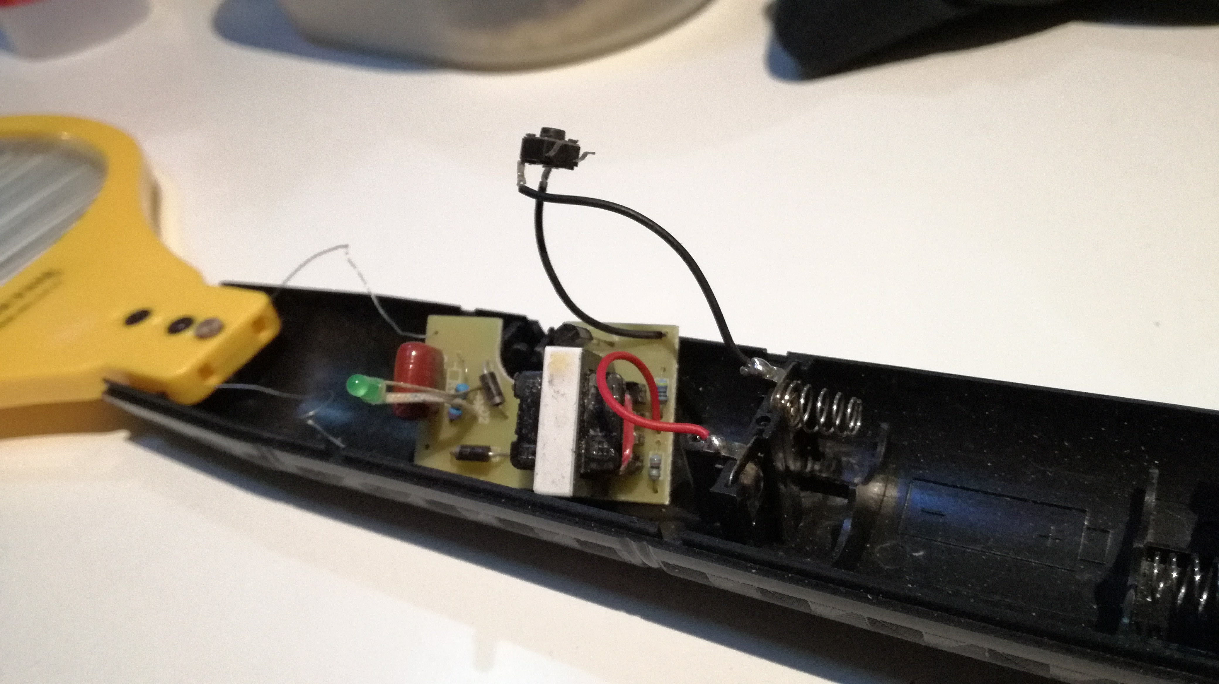
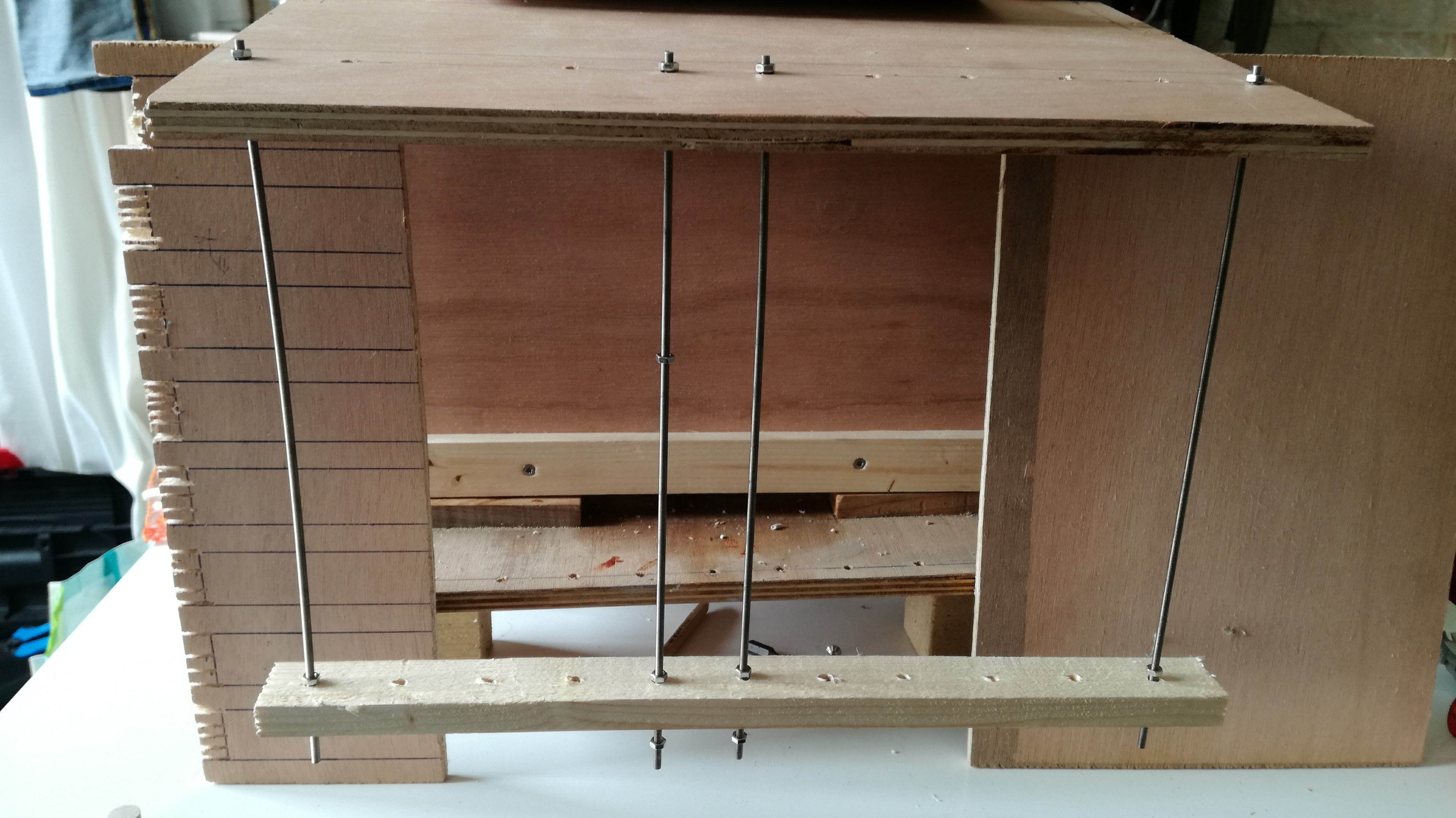
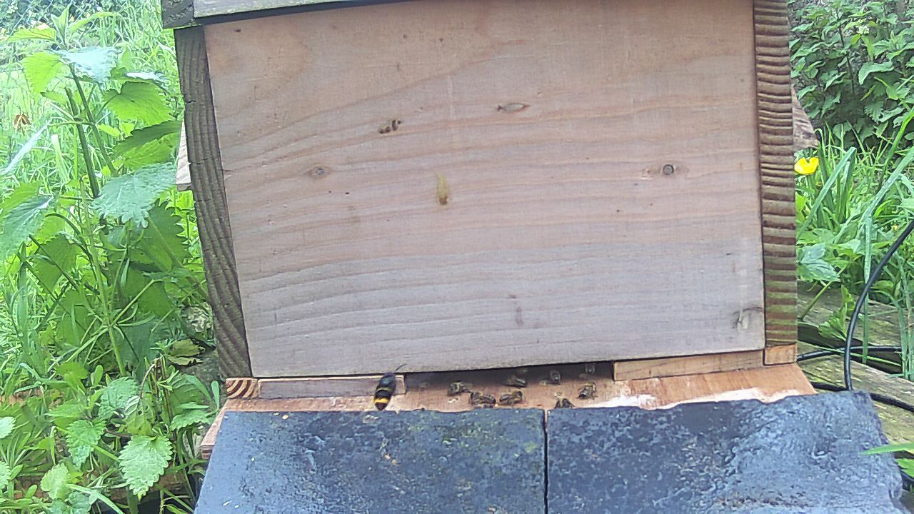
I would like to make an electrical barrier to protect my beehive from vespa velutina using a mosquito racket :
-
Hello,
I would like to use the mosfet of the Ceech board: ATmega328p board w/ NRF24l01+ socket LTC4079
In the doc is indicated that it is wired do digital 3.
I have modified the "blink without delay" sketchconst int MOSFET = 3; int loadState = LOW; unsigned long previousMillis = 0; const long interval = 2000; void setup() { // put your setup code here, to run once: pinMode(MOSFET, OUTPUT); digitalWrite(MOSFET, HIGH); Serial.begin(9600); } void loop() { unsigned long currentMillis = millis(); if (currentMillis - previousMillis >= interval) { // save the last time you blinked the LED previousMillis = currentMillis; // if the LED is off turn it on and vice-versa: if (loadState == LOW) { loadState = HIGH; } else { loadState = 0; } // set the LED with the ledState of the variable: digitalWrite(MOSFET, loadState); Serial.print("state: ");Serial.println(loadState); } }I don't understand how it works, I have tried to measure continuity with a voltmeter, I have tried to wire a led between vcc, cuting the gnd with the mosfet without success.
Does anyone would be explain how I can use it ?
I would like to make an electrical barrier to protect my beehive from vespa velutina using a mosquito racket :
-
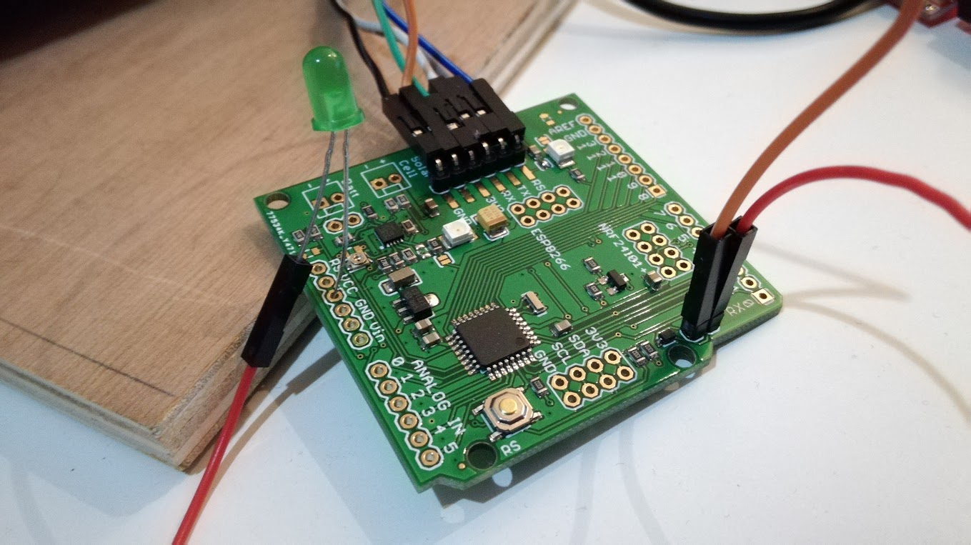
You need to connect the LED (+resistor) like this:
- Positive: Vcc Pin
- Negative: The pin with the orange/brown wire in your picture.
the mosfet onboard is N-channel, so it will switch the negative (GND) line.
-
Hello @Yveaux, hello @rvendrame: thank you.
the led is still alive :-)
With the sketch , I can see the led blinking if it is wired between gnd and d3.
@rvendrame I should miss something because the led stay off with your instructions.
Maybe @ceech will see this my SOS :-)
-
Hello @Yveaux, hello @rvendrame: thank you.
the led is still alive :-)
With the sketch , I can see the led blinking if it is wired between gnd and d3.
@rvendrame I should miss something because the led stay off with your instructions.
Maybe @ceech will see this my SOS :-)
@Jodaille , it works for me, when wiring the led between Vcc and the non-named pin where you put that orange (or brown?) wire. There is where I found the MOSFET N-channel drain is connected.

Home Assistant / Vera Plus UI7
ESP8266 GW + mySensors 2.3.2
Alexa / Google Home -
@Jodaille , it works for me, when wiring the led between Vcc and the non-named pin where you put that orange (or brown?) wire. There is where I found the MOSFET N-channel drain is connected.
Thank you @rvendrame ,
it works, I attach a Ceech's schema, using D4 instead of D3 :-)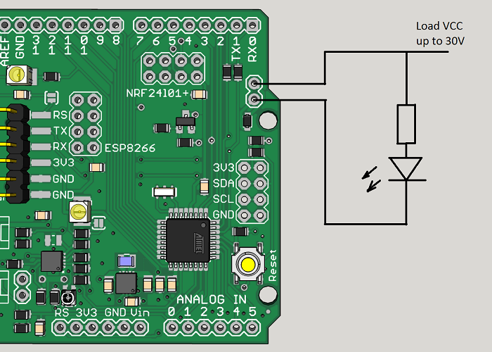

Hello! It looks like you're interested in this conversation, but you don't have an account yet.
Getting fed up of having to scroll through the same posts each visit? When you register for an account, you'll always come back to exactly where you were before, and choose to be notified of new replies (either via email, or push notification). You'll also be able to save bookmarks and upvote posts to show your appreciation to other community members.
With your input, this post could be even better 💗
Register Login