nRF5 action!
-
Had the nrf52dk shipped from arrow to the Netherlands. Because it was above 22 euro( something like that) DHL had to let it apply tax and some administration cost.
The board costed 28 euro(inc shipping). The tax office estimate was that is was around 120 euro??? so they charged me a little to much. I filled in some forms to get some of the taxes back.
When the board arrived I had to pay DHL 43 euro . So getting it though customes cost more than the board itself. 😏
@Omemanti said in nRF5 Bluetooth action!:
When the board arrived I had to pay DHL 43 euro .
DHL is selling it's shipment service cheaper to shops so the cost seems interesting for buyer. But their trick is to force you to pay some "service fee" when you receive your parcel in addition to custom taxes. This is borderline scam IMHO as this fee is mandatory and has a fixed value for each destination country, so DHL should include it upfront when customer orders.
No more DHL shipment for me. -
@NeverDie said in nRF5 Bluetooth action!:
@d00616 Is it still the case that we're limited to a single interrupt? For instance, I'd like to put the nRF52832 to wake-up periodically as a heartbeat where it reports its battery level, and I also want it to wake-up if a particular pin goes HIGH (e.g. if a PIR sensor is triggered). Presently I'm using the RTC to provide the one interrupt, and I use the PPI to create an RTC interrupt if it detects that the PIR sensor pin has gone HIGH. Then the interrupt code must determine the true cause of the interrupt. It would be cleaner if I could separate them into separate interrupts.
You can wake up the MCU via:
- GPIO pin sense; used for sleep()
- GPIOTE; consumes less engergy but pin must be dedected in software (0.1µA-0.5µA)
- LPCOMP (0.5µA)
- QDEC (5µA)
The interrupts for LPCOMP and QDEC are not allocated by the arduino-port. I think the LPCOMP is a good point to start with.
@d00616 said in nRF5 Bluetooth action!:
@NeverDie said in nRF5 Bluetooth action!:
@d00616 Is it still the case that we're limited to a single interrupt? For instance, I'd like to put the nRF52832 to wake-up periodically as a heartbeat where it reports its battery level, and I also want it to wake-up if a particular pin goes HIGH (e.g. if a PIR sensor is triggered). Presently I'm using the RTC to provide the one interrupt, and I use the PPI to create an RTC interrupt if it detects that the PIR sensor pin has gone HIGH. Then the interrupt code must determine the true cause of the interrupt. It would be cleaner if I could separate them into separate interrupts.You can wake up the MCU via:
- GPIO pin sense; used for sleep()
- GPIOTE; consumes less engergy but pin must be dedected in software (0.1µA-0.5µA)
- LPCOMP (0.5µA)
- QDEC (5µA)
The interrupts for LPCOMP and QDEC are not allocated by the arduino-port. I think the LPCOMP is a good point to start with.
I have it now where LPCOMP does detect pin AIN1 (i.e. pin P0.03) going HIGH, but it still doesn't wake-up the MCU,
and the interrupt code never runs. I could use the PPI to trigger an RTC interrupt when it detects the NRF_LPCOMP->EVENTS_UP event, which would wake up the MCU, but then I'm back to square one. Is that the best that can be done given the current state of the software?#define MY_CORE_ONLY #include <nrf.h> #include <MySensors.h> uint32_t blinkCounter=0; uint32_t interruptCounter=0; bool button_pressed=false; void setup() { Serial.begin(9600); Serial.println(); Serial.println("Starting..."); // Enable interrupt NVIC_SetPriority(LPCOMP_IRQn, 15); NVIC_ClearPendingIRQ(LPCOMP_IRQn); NVIC_EnableIRQ(LPCOMP_IRQn); hwPinMode(LED_BUILTIN,OUTPUT_H0H1); //hwPinMode(PIN_BUTTON1,INPUT); NRF_LPCOMP->PSEL=1; // monitor AIN1 (pin P0.03). while (!(NRF_LPCOMP->PSEL==1)) {} //wait until confirmed NRF_LPCOMP->REFSEL=3; // choose 1/2 VDD as the reference voltage while (!(NRF_LPCOMP->REFSEL==3)) {} //wait until confirmed NRF_LPCOMP->INTENSET=B0100; //Enable interrupt for UP event while (!(NRF_LPCOMP->INTENSET==B0100)) {} //wait until confirmed NRF_LPCOMP->ENABLE=1; //Enable LPCOMP while (!(NRF_LPCOMP->ENABLE==1)) {} //wait until confirmed NRF_LPCOMP->TASKS_START=1; //start the LPCOMP while (!(NRF_LPCOMP->EVENTS_READY)) {} //wait until ready } void loop() { Serial.print(blinkCounter++); Serial.println("HIGH"); digitalWrite(LED_BUILTIN,HIGH); delay(20); /* if (NRF_LPCOMP->EVENTS_UP) { digitalWrite(LED_BUILTIN,HIGH); delay(2000); NRF_LPCOMP->EVENTS_UP=0; //Clear the semaphore } */ if (button_pressed) { digitalWrite(LED_BUILTIN,HIGH); delay(2000); button_pressed=false; //Clear the semaphore NRF_LPCOMP->EVENTS_UP=0; //Clear the semaphore } digitalWrite(LED_BUILTIN,LOW); hwSleep(5000); } // * Reset events and read back on nRF52 //* http://infocenter.nordicsemi.com/pdf/nRF52_Series_Migration_v1.0.pdf #if __CORTEX_M == 0x04 #define NRF5_RESET_EVENT(event) \ event = 0; \ (void)event #else #define NRF5_RESET_EVENT(event) event = 0 #endif // This must be in one line //extern "C" { void GPIO_IRQHandler(void) {interruptCounter++; NRF5_RESET_EVENT(NRF_RTC0->EVENTS_OVRFLW); NRF_RTC0->EVENTS_OVRFLW=0; }} extern "C" { void LPCOMP_IRQHandler(void) {button_pressed=true; interruptCounter++; NRF5_RESET_EVENT(NRF_LPCOMP->EVENTS_UP); NRF_LPCOMP->EVENTS_UP=0; }} -
@d00616 said in nRF5 Bluetooth action!:
@NeverDie said in nRF5 Bluetooth action!:
@d00616 Is it still the case that we're limited to a single interrupt? For instance, I'd like to put the nRF52832 to wake-up periodically as a heartbeat where it reports its battery level, and I also want it to wake-up if a particular pin goes HIGH (e.g. if a PIR sensor is triggered). Presently I'm using the RTC to provide the one interrupt, and I use the PPI to create an RTC interrupt if it detects that the PIR sensor pin has gone HIGH. Then the interrupt code must determine the true cause of the interrupt. It would be cleaner if I could separate them into separate interrupts.You can wake up the MCU via:
- GPIO pin sense; used for sleep()
- GPIOTE; consumes less engergy but pin must be dedected in software (0.1µA-0.5µA)
- LPCOMP (0.5µA)
- QDEC (5µA)
The interrupts for LPCOMP and QDEC are not allocated by the arduino-port. I think the LPCOMP is a good point to start with.
I have it now where LPCOMP does detect pin AIN1 (i.e. pin P0.03) going HIGH, but it still doesn't wake-up the MCU,
and the interrupt code never runs. I could use the PPI to trigger an RTC interrupt when it detects the NRF_LPCOMP->EVENTS_UP event, which would wake up the MCU, but then I'm back to square one. Is that the best that can be done given the current state of the software?#define MY_CORE_ONLY #include <nrf.h> #include <MySensors.h> uint32_t blinkCounter=0; uint32_t interruptCounter=0; bool button_pressed=false; void setup() { Serial.begin(9600); Serial.println(); Serial.println("Starting..."); // Enable interrupt NVIC_SetPriority(LPCOMP_IRQn, 15); NVIC_ClearPendingIRQ(LPCOMP_IRQn); NVIC_EnableIRQ(LPCOMP_IRQn); hwPinMode(LED_BUILTIN,OUTPUT_H0H1); //hwPinMode(PIN_BUTTON1,INPUT); NRF_LPCOMP->PSEL=1; // monitor AIN1 (pin P0.03). while (!(NRF_LPCOMP->PSEL==1)) {} //wait until confirmed NRF_LPCOMP->REFSEL=3; // choose 1/2 VDD as the reference voltage while (!(NRF_LPCOMP->REFSEL==3)) {} //wait until confirmed NRF_LPCOMP->INTENSET=B0100; //Enable interrupt for UP event while (!(NRF_LPCOMP->INTENSET==B0100)) {} //wait until confirmed NRF_LPCOMP->ENABLE=1; //Enable LPCOMP while (!(NRF_LPCOMP->ENABLE==1)) {} //wait until confirmed NRF_LPCOMP->TASKS_START=1; //start the LPCOMP while (!(NRF_LPCOMP->EVENTS_READY)) {} //wait until ready } void loop() { Serial.print(blinkCounter++); Serial.println("HIGH"); digitalWrite(LED_BUILTIN,HIGH); delay(20); /* if (NRF_LPCOMP->EVENTS_UP) { digitalWrite(LED_BUILTIN,HIGH); delay(2000); NRF_LPCOMP->EVENTS_UP=0; //Clear the semaphore } */ if (button_pressed) { digitalWrite(LED_BUILTIN,HIGH); delay(2000); button_pressed=false; //Clear the semaphore NRF_LPCOMP->EVENTS_UP=0; //Clear the semaphore } digitalWrite(LED_BUILTIN,LOW); hwSleep(5000); } // * Reset events and read back on nRF52 //* http://infocenter.nordicsemi.com/pdf/nRF52_Series_Migration_v1.0.pdf #if __CORTEX_M == 0x04 #define NRF5_RESET_EVENT(event) \ event = 0; \ (void)event #else #define NRF5_RESET_EVENT(event) event = 0 #endif // This must be in one line //extern "C" { void GPIO_IRQHandler(void) {interruptCounter++; NRF5_RESET_EVENT(NRF_RTC0->EVENTS_OVRFLW); NRF_RTC0->EVENTS_OVRFLW=0; }} extern "C" { void LPCOMP_IRQHandler(void) {button_pressed=true; interruptCounter++; NRF5_RESET_EVENT(NRF_LPCOMP->EVENTS_UP); NRF_LPCOMP->EVENTS_UP=0; }}Getting closer... The LPCOMP interrupt code does run, but the main loop doesn't resume until the RTC timer makes it resume because the programmed time interval has expired.
I know this is true because if, during sleep, I make AIN1 go HIGH, and then LOW, then when the MCU later wakes up because of the RTC, it so indicates by making the LED go HIGH for 2 seconds. However, even though there's now solid proof that the LPCOMP interrupt hardware does execute, the main loop doesn't immediately resume, as it does when the RTC times out.
So.... How to make the main loop immediately resume whenever LPCOMP goes UP?
-
Getting closer... The LPCOMP interrupt code does run, but the main loop doesn't resume until the RTC timer makes it resume because the programmed time interval has expired.
I know this is true because if, during sleep, I make AIN1 go HIGH, and then LOW, then when the MCU later wakes up because of the RTC, it so indicates by making the LED go HIGH for 2 seconds. However, even though there's now solid proof that the LPCOMP interrupt hardware does execute, the main loop doesn't immediately resume, as it does when the RTC times out.
So.... How to make the main loop immediately resume whenever LPCOMP goes UP?
Well, I have to re-build the timer part of this, and clean up the code, but at least now a PIR sensor trigger will immediately wake-up the MCU. That's progress! Unfortunately, current drawn during sleep is now 456ua, which is much higher than it should be.
#define MY_CORE_ONLY #include <nrf.h> #include <MySensors.h> uint32_t rtcInterruptCounter=0; uint32_t buttonPressInterruptCounter=0; bool button_pressed=false; void myHwSleepPrepare(unsigned long ms) { // Idle serial device NRF_UART0->TASKS_STOPRX = 1; NRF_UART0->TASKS_STOPTX = 1; NRF_UART0->TASKS_SUSPEND = 1; //NRF_UART0->ENABLE=0; //disable UART0 //NRF_CLOCK->TASKS_HFCLKSTOP = 1; // Enable low power sleep mode NRF_POWER->TASKS_LOWPWR = 1; } // Sleep in System ON mode inline void doTheSleep() { __WFE(); __SEV(); __WFE(); } void myHwSleepEnd(unsigned long ms) { // Start HFCLK //if (nrf5_pwr_hfclk) { if (false) { NRF_CLOCK->EVENTS_HFCLKSTARTED = 0; NRF_CLOCK->TASKS_HFCLKSTART = 1; while (NRF_CLOCK->EVENTS_HFCLKSTARTED == 0) ; // Enable low latency sleep mode //NRF_POWER->TASKS_CONSTLAT = 1; } } void myHwSleep(unsigned long ms) { myHwSleepPrepare(ms); doTheSleep(); //now sleeping myHwSleepEnd(ms); } void setup() { //Serial.begin(9600); //Serial.println(); //Serial.println("Starting..."); // Enable interrupt NVIC_SetPriority(LPCOMP_IRQn, 15); NVIC_ClearPendingIRQ(LPCOMP_IRQn); NVIC_EnableIRQ(LPCOMP_IRQn); hwPinMode(LED_BUILTIN,OUTPUT_H0H1); //hwPinMode(PIN_BUTTON1,INPUT); NRF_LPCOMP->PSEL=1; // monitor AIN1 (pin P0.03). while (!(NRF_LPCOMP->PSEL==1)) {} //wait until confirmed NRF_LPCOMP->REFSEL=3; // choose 1/2 VDD as the reference voltage while (!(NRF_LPCOMP->REFSEL==3)) {} //wait until confirmed NRF_LPCOMP->INTENSET=B0100; //Enable interrupt for UP event while (!(NRF_LPCOMP->INTENSET==B0100)) {} //wait until confirmed NRF_LPCOMP->ENABLE=1; //Enable LPCOMP while (!(NRF_LPCOMP->ENABLE==1)) {} //wait until confirmed NRF_LPCOMP->TASKS_START=1; //start the LPCOMP while (!(NRF_LPCOMP->EVENTS_READY)) {} //wait until ready //NRF_PPI->CH[0].EEP = (uint32_t)&NRF_LPCOMP->EVENTS_UP; //If PIR sensor is triggered //NRF_PPI->CH[0].TEP = (uint32_t)&NRF_RTC0->TASKS_TRIGOVRFLW; //make the RTC wake-up the MCU //NRF_PPI->CHENSET=B00000001; //enable Channel 0. NRF_RTC0->INTENSET = B10; //interrupt MCU if an OVRFLW is detected. while (NRF_RTC0->INTENSET != B10) {} //wait until confirmed } void loop() { //Serial.print(blinkCounter++); //Serial.println("HIGH"); digitalWrite(LED_BUILTIN,HIGH); delay(20); /* if (NRF_LPCOMP->EVENTS_UP) { digitalWrite(LED_BUILTIN,HIGH); delay(2000); NRF_LPCOMP->EVENTS_UP=0; //Clear the semaphore } */ if (button_pressed) { digitalWrite(LED_BUILTIN,HIGH); delay(2000); button_pressed=false; //Clear the semaphore NRF_LPCOMP->EVENTS_UP=0; //Clear the semaphore } digitalWrite(LED_BUILTIN,LOW); myHwSleep(5000); } // * Reset events and read back on nRF52 //* http://infocenter.nordicsemi.com/pdf/nRF52_Series_Migration_v1.0.pdf #if __CORTEX_M == 0x04 #define NRF5_RESET_EVENT(event) \ event = 0; \ (void)event #else #define NRF5_RESET_EVENT(event) event = 0 #endif // This must be in one line extern "C" { void RTC0_IRQHandler(void) {rtcInterruptCounter++; NRF5_RESET_EVENT(NRF_RTC0->EVENTS_OVRFLW); NRF_RTC0->EVENTS_OVRFLW=0; }} extern "C" { void LPCOMP_IRQHandler(void) {button_pressed=true; buttonPressInterruptCounter++; NRF5_RESET_EVENT(NRF_LPCOMP->EVENTS_UP); NRF_LPCOMP->EVENTS_UP=0; }} -
Aha! Most likely the high current draw is from the high frequency clock, which I need to turn off prior to sleep but haven't done yet.
Anyhow, the basic question remains and boils down to this: Can I have both
    // Enable interrupt
  NVIC_SetPriority(LPCOMP_IRQn, 15);
  NVIC_ClearPendingIRQ(LPCOMP_IRQn);
  NVIC_EnableIRQ(LPCOMP_IRQn);
AND an equivalent incantation for the RTC both active at the same time? Or am I forced into having it be just one or the other?
-
Around 30 feet, through some walls, but at 2mbps. I realize that's not very far, but even so the measured packet loss (informal testing) is pretty high at that speed. I can see why most people default to 250kbps instead.
I don't have the 840 dev kit yet, mostly because I don't see anyother 840 modules on the market right now.
@NeverDie Did you manage to get more than 10m ? maybe by another modules.
I thought the nrf52 will have better range !
-
@NeverDie
Exactly. There are two pads labelled SWD and SWC, originally meant for pogo pins.
I patched them with wires to the pin header.
Programming with a Chinese STLink V2 clone works flawlessly.@Uhrheber I am a bit confused. To program the nRF52 from eByte I need a special programmer but they are expensive. So you mean you used a clone StLink V2 and it worked fine ?
I found this.
-
@Uhrheber I am a bit confused. To program the nRF52 from eByte I need a special programmer but they are expensive. So you mean you used a clone StLink V2 and it worked fine ?
I found this.
@ahmedadelhosni
Sure, I'm using a similar one.
Why wouldn't it work? The nrf52 is an ARM Mx, like the ST chips. The programming interface is the same. You could also use one of the many other ARM programmers, like J-Link, or nearly any JTAG programmer supported by OpenOCD.Just follow this guide: https://www.openhardware.io/view/376/MySensors-NRF5-Platform
And: https://github.com/sandeepmistry/arduino-nRF5/#installing -
@ahmedadelhosni
Sure, I'm using a similar one.
Why wouldn't it work? The nrf52 is an ARM Mx, like the ST chips. The programming interface is the same. You could also use one of the many other ARM programmers, like J-Link, or nearly any JTAG programmer supported by OpenOCD.Just follow this guide: https://www.openhardware.io/view/376/MySensors-NRF5-Platform
And: https://github.com/sandeepmistry/arduino-nRF5/#installing@Uhrheber Great. Thanks for the help.
So if I understand well. If I have a TIVA board like TM4C123G Launchpad and it is ARM Mx also, then I can use it to program my nRF ?
This is the datasheet for the board : http://www.ti.com/lit/ug/spmu296/spmu296.pdf
I searched and found those links describing how to use the Launchad but I am not sure whether this will work for nRF also or not.
http://processors.wiki.ti.com/index.php/Stellaris_LM4F120_LaunchPad_Debug_How_To
http://ucsolutions.blogspot.com.eg/2014/08/ti-launchpad-as-external-debugger-with.htmlThanks.
-
@Uhrheber Great. Thanks for the help.
So if I understand well. If I have a TIVA board like TM4C123G Launchpad and it is ARM Mx also, then I can use it to program my nRF ?
This is the datasheet for the board : http://www.ti.com/lit/ug/spmu296/spmu296.pdf
I searched and found those links describing how to use the Launchad but I am not sure whether this will work for nRF also or not.
http://processors.wiki.ti.com/index.php/Stellaris_LM4F120_LaunchPad_Debug_How_To
http://ucsolutions.blogspot.com.eg/2014/08/ti-launchpad-as-external-debugger-with.htmlThanks.
@ahmedadelhosni said in nRF5 Bluetooth action!:
@Uhrheber Great. Thanks for the help.
So if I understand well. If I have a TIVA board like TM4C123G Launchpad and it is ARM Mx also, then I can use it to program my nRF ?
This is the datasheet for the board : http://www.ti.com/lit/ug/spmu296/spmu296.pdf
I searched and found those links describing how to use the Launchad but I am not sure whether this will work for nRF also or not.
http://processors.wiki.ti.com/index.php/Stellaris_LM4F120_LaunchPad_Debug_How_To
http://ucsolutions.blogspot.com.eg/2014/08/ti-launchpad-as-external-debugger-with.htmlThanks.
I think it's a question of the licence of the programmer that is on your board.
For example the J-Link version on the NRF52 DK is only allowed to program NRF52 and NRF51 chips. It's logic because the NRF52DK is just over 30$ while a J-Link programmer is x00$.
You have pins SWDIO and SWDCLK on pins PC0 and PC1 of your board so just try it and you will know :) -
Guys, your best bet is to reflash STM32 Bluepill into BlackMagicProbe.
It's awesome!
https://medium.com/@paramaggarwal/converting-an-stm32f103-board-to-a-black-magic-probe-c013cf2cc38c -
Anyhow, the basic question remains and boils down to this: Can I have both
    // Enable interrupt
  NVIC_SetPriority(LPCOMP_IRQn, 15);
  NVIC_ClearPendingIRQ(LPCOMP_IRQn);
  NVIC_EnableIRQ(LPCOMP_IRQn);
AND an equivalent incantation for the RTC both active at the same time? Or am I forced into having it be just one or the other?
@NeverDie said in nRF5 Bluetooth action!:
Anyhow, the basic question remains and boils down to this: Can I have both
    // Enable interrupt
  NVIC_SetPriority(LPCOMP_IRQn, 15);
  NVIC_ClearPendingIRQ(LPCOMP_IRQn);
  NVIC_EnableIRQ(LPCOMP_IRQn);
AND an equivalent incantation for the RTC both active at the same time? Or am I forced into having it be just one or the other?
@d00616 Any thoughts or comments regarding this?
-
@NeverDie said in nRF5 Bluetooth action!:
Anyhow, the basic question remains and boils down to this: Can I have both
    // Enable interrupt
  NVIC_SetPriority(LPCOMP_IRQn, 15);
  NVIC_ClearPendingIRQ(LPCOMP_IRQn);
  NVIC_EnableIRQ(LPCOMP_IRQn);
AND an equivalent incantation for the RTC both active at the same time? Or am I forced into having it be just one or the other?
@d00616 Any thoughts or comments regarding this?
@NeverDie said in nRF5 Bluetooth action!:
@d00616 Any thoughts or comments regarding this?
Sorry, I can't help here. Maybe, the interrupt priority can be used only once and you have to use another priority for RTC or LPCOMP.
-
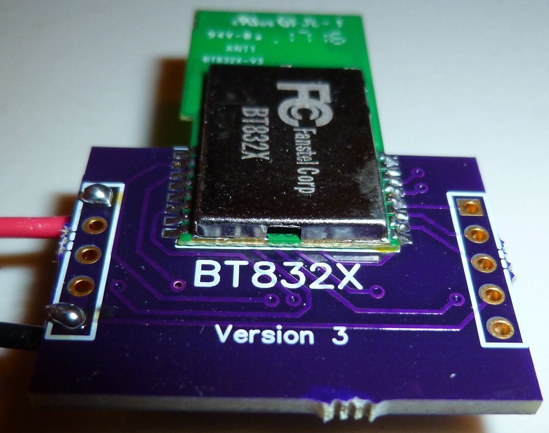
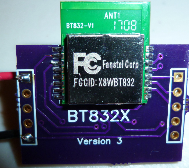
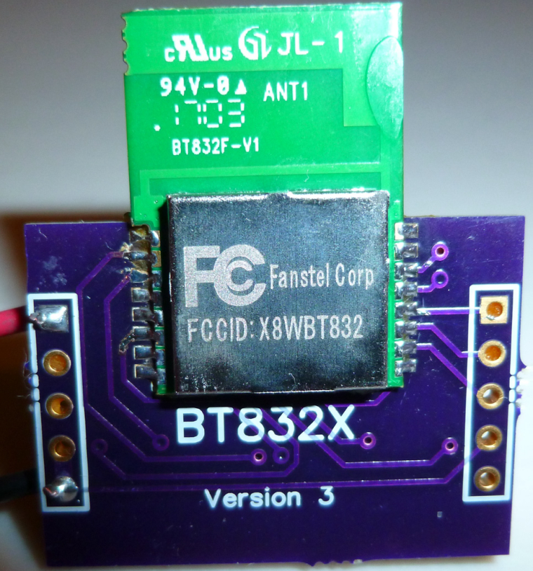
I tried out the Fanstel BT832X (i.e. nRF52832 with PA and LNA) today:
Good news:
- Even without the PA turned on, the range seems a lot better than if transmitting from an Ebyte module.
- Also, I've confirmed that it comes with DCDC built-in.
- With the PA turned on, the range is comparable to, and perhaps even better than, the RFaxis I reviewed earlier in this thread.
With the PA turned on, it consumes about 250ma.
-
@d00616 I hooked up the Fanstel BT832A. Although it appeared to flash and verify correctly, I couldn't get it to do anything--not even blink. Is there any chance that it's downsized flash/memory has something to do with it? "Flash/RAM memories in BT832 are 512KB/64KB. They are 192KB/24KB in BT832A." So, as an experiment, I hooked up a BT832 in its place on the same board, and it's able to transmit and blink just fine. In total, the only differences between the two are:
- Cortex M4F in BT832 has hardware DSP and floating point instructions. Cortex M4 in BT832A has hardware DSP instructions but it does not have floating point unit to support hardware instruction.
- Flash/RAM memories in BT832 are 512KB/64KB. They are 192KB/24KB in BT832A.
- BT832 has NFC tag interface. BT832A does not have NFC tag
interface.
I think we can rule out #3. So, if it isn't #2, then is perhaps #1 a factor? I wouldn't think so.
The solder connections seemed correct. I suppose it's possible I simply got a bad module, but I'm doubtful that's it.
Here's a photo of it installed on a BT832X board, which is pin-for-pin compatible:
@NeverDie said in nRF5 Bluetooth action!:
I think we can rule out #3. So, if it isn't #2, then is perhaps #1 a factor? I wouldn't think so.
I think, you have to do more things:
- Change compiler attributes to disable FPU support
- Change the memory layout in linker scripts. Look into boards definition. Linker scripts are placed under ./cores/nRF5/SDK/components/toolchain/gcc/ The SDK14 has scripts supporting the nrf52810
- The SDK14 has an dedicated startup code (gcc_startup_nrf52810.S), I don't know if this relevant for arduino-nrf5
I think there is more to do than compile the code. I think the SDK code for arduino-nrf5 must be updated to SDK 14, then a nre MCU must be defined.
I have compared the startup code. The difference is in the interrupt vector. It should work with the NRF52832 startup code, but the linker script must be changed.
-
@NeverDie said in nRF5 Bluetooth action!:
I think we can rule out #3. So, if it isn't #2, then is perhaps #1 a factor? I wouldn't think so.
I think, you have to do more things:
- Change compiler attributes to disable FPU support
- Change the memory layout in linker scripts. Look into boards definition. Linker scripts are placed under ./cores/nRF5/SDK/components/toolchain/gcc/ The SDK14 has scripts supporting the nrf52810
- The SDK14 has an dedicated startup code (gcc_startup_nrf52810.S), I don't know if this relevant for arduino-nrf5
I think there is more to do than compile the code. I think the SDK code for arduino-nrf5 must be updated to SDK 14, then a nre MCU must be defined.
I have compared the startup code. The difference is in the interrupt vector. It should work with the NRF52832 startup code, but the linker script must be changed.
@d00616 Also, at least so far, I haven't been able to get the Fanstel modules to receive anything. At first I thought it must be an LNA thing, but I tried it just now on a Fanstel module without LNA, and although it can transmit and blink just fine, the regular receive code isn't working. Any theories on that?
-
@d00616 Also, at least so far, I haven't been able to get the Fanstel modules to receive anything. At first I thought it must be an LNA thing, but I tried it just now on a Fanstel module without LNA, and although it can transmit and blink just fine, the regular receive code isn't working. Any theories on that?
@NeverDie said in nRF5 Bluetooth action!:
@d00616 Also, at least so far, I haven't been able to get the Fanstel modules to receive anything. At first I thought it must be an LNA thing, but I tried it just now on a Fanstel module without LNA, and although it can transmit and blink just fine, the regular receive code isn't working. Any theories on that?
I think this could be the memory layout -> linker script. My try to port Arduino to nrf51 in 2014 is failed at the same state. Blink was ok. Using something with memory are failed. The reason was a wrong linker script. At this time Nordic hasen't released (L)GPG compatible scripts.
Edit: I think it's possible to add the 82810 to https://github.com/mysensors/ArduinoHwNRF5 by changing the board definition and add the missing linker script into the variant folder.