Skip to content
  • MySensors
  • OpenHardware.io
  • Categories
  • Recent
  • Tags
  • Popular
Skins
  • Light
  • Brite
  • Cerulean
  • Cosmo
  • Flatly
  • Journal
  • Litera
  • Lumen
  • Lux
  • Materia
  • Minty
  • Morph
  • Pulse
  • Sandstone
  • Simplex
  • Sketchy
  • Spacelab
  • United
  • Yeti
  • Zephyr
  • Dark
  • Cyborg
  • Darkly
  • Quartz
  • Slate
  • Solar
  • Superhero
  • Vapor

  • Default (No Skin)
  • No Skin
Collapse
Brand Logo
  1. Home
  2. My Project
  3. nRF5 action!

nRF5 action!

Scheduled Pinned Locked Moved My Project
1.9k Posts 49 Posters 631.3k Views 44 Watching
  • Oldest to Newest
  • Newest to Oldest
  • Most Votes
Reply
  • Reply as topic
Log in to reply
This topic has been deleted. Only users with topic management privileges can see it.
  • NeverDieN NeverDie

    When you combine my BT832XE gateway with the LNA on this external "booster," the result is really great reception range, even at 2Mbps:
    0_1509558101829_awesome.jpg
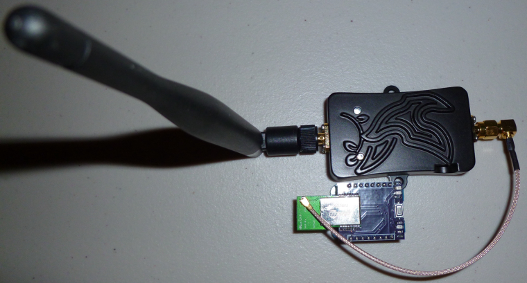
    I think this combo will be hard to beat. In fact, I can receive even from nRF24L01's that are far away (further away than a nRF24L01 with PA+LNA can receive). :)

    U Offline
    U Offline
    Uhrheber
    wrote on last edited by
    #1255

    @NeverDie said in nRF5 Bluetooth action!:

    BT832XE

    What booster is it?

    1 Reply Last reply
    0
    • NeverDieN NeverDie

      @rmtucker said in nRF5 Bluetooth action!:

      I would love to make a small pcb for the NRF core to plug in to instead of the big motherboard as below

      Here you go: https://www.openhardware.io/view/510/Button-cell-Temperature-Humidity-sensor#tabs-bom

      This should be even smaller and less expensive than what you wished for. I made it for the Si7021 because I had some extras laying around. The BME280 would also be a good choice.

      NeverDieN Offline
      NeverDieN Offline
      NeverDie
      Hero Member
      wrote on last edited by NeverDie
      #1256

      @NeverDie said in nRF5 Bluetooth action!:

      @rmtucker said in nRF5 Bluetooth action!:

      I would love to make a small pcb for the NRF core to plug in to instead of the big motherboard as below

      Here you go: https://www.openhardware.io/view/510/Button-cell-Temperature-Humidity-sensor#tabs-bom

      This should be even smaller and less expensive than what you wished for. I made it for the Si7021 because I had some extras laying around. The BME280 would also be a good choice.

      I'm realizing now that I can get a decent temperature reading from just the nRF5x chip itself. With calibration it should get even better.

      rmtuckerR 1 Reply Last reply
      1
      • NeverDieN Offline
        NeverDieN Offline
        NeverDie
        Hero Member
        wrote on last edited by
        #1257

        Today I finally received the PTR9618PA that I ordered a while back:
        0_1510110556809_ptr1.jpg
        0_1510110572062_ptr2.jpg

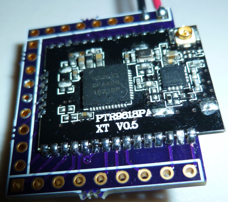
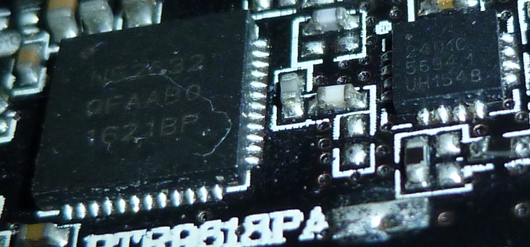
        Like the Fanstel modules, it lacks a 32.768Khz crystal oscillator. Also, as you can see from the second photo, the PA/LNA chip is the 2401C: http://www.skyworksinc.com/Product/3213/RFX2401C

        1 Reply Last reply
        0
        • NeverDieN NeverDie

          @NeverDie said in nRF5 Bluetooth action!:

          @rmtucker said in nRF5 Bluetooth action!:

          I would love to make a small pcb for the NRF core to plug in to instead of the big motherboard as below

          Here you go: https://www.openhardware.io/view/510/Button-cell-Temperature-Humidity-sensor#tabs-bom

          This should be even smaller and less expensive than what you wished for. I made it for the Si7021 because I had some extras laying around. The BME280 would also be a good choice.

          I'm realizing now that I can get a decent temperature reading from just the nRF5x chip itself. With calibration it should get even better.

          rmtuckerR Offline
          rmtuckerR Offline
          rmtucker
          wrote on last edited by
          #1258

          @NeverDie said in nRF5 Bluetooth action!:

          @NeverDie said in nRF5 Bluetooth action!:

          I'm realizing now that I can get a decent temperature reading from just the nRF5x chip itself. With calibration it should get even better.

          I used the internal temperature in the past but i can not remember how i did it?
          Do you have some example code to remind me?

          NeverDieN 1 Reply Last reply
          0
          • rmtuckerR rmtucker

            @NeverDie said in nRF5 Bluetooth action!:

            @NeverDie said in nRF5 Bluetooth action!:

            I'm realizing now that I can get a decent temperature reading from just the nRF5x chip itself. With calibration it should get even better.

            I used the internal temperature in the past but i can not remember how i did it?
            Do you have some example code to remind me?

            NeverDieN Offline
            NeverDieN Offline
            NeverDie
            Hero Member
            wrote on last edited by NeverDie
            #1259

            @rmtucker said in nRF5 Bluetooth action!:

            Do you have some example code to remind me?

            /*
             * This example sketch shows how you can manage the nRF5 pin mapping as part of your code.
             * You can use the method for any nRF51822 or nRF52832 board or module.
             * 
             * Most components, like UART, SPI, Wire Bus, of the nRF5 series chips don't
             * have a fixed pin mapping. There are some pins with restrictions like analog
             * inputs, NFC or pins near the radio module. Please refer the latest
             * documentation about pin restrictions at http://infocenter.nordicsemi.com 
             * 
             * To use the custom pin mapping you have to do following steps:
             * 
             * 1. Install "arduino-nrf5" like described at
             *    https://github.com/sandeepmistry/arduino-nRF5/
             * 2. Install the "My Sensors nRF5 Boards" with the board manager like
             *    explained at https://github.com/mysensors/ArduinoBoards
             * 3. Copy the files "MyNRF5Board.cpp" and "MyNRF5Board.h" from
             *    "MyNRF5Board" example into your sketch.
             * 4. Modify pin mappings in "MyNRF5Board.cpp" and "MyNRF5Board.h" to fit
             *    your requirements.
             * 5. Select "MyNRF5Board nrf52832" or "MyNRF5Board nrf52822" as your board.
             *    Choose the correct parameters and programmer in the Tools menu.
             */
            
            // Many thanks to d00616 for this framework!
            
            //------------------------------------------------------------------------------------------------------------------------------------------------------------------------
            
            //Simple program to demonstrate that both the LED and Serial  and Temperature are working correctly on the breakout board:
            // https://www.openhardware.io/view/471/Ebyte-nRF52832-Small-Breakout-Board
            
            //Note: Compile and upload from Arduino IDE using "MyNRF5Board nRF51822" as the board and with 16K RAM, RC Oscillator, and no bootloader as the options.  
            //


            #define MY_CORE_ONLY
            
            #include <nrf.h>
            #include <MySensors.h>
            
            
            void setup() {
              hwPinMode(LED_BUILTIN,OUTPUT_D0H1);
              digitalWrite(LED_BUILTIN,HIGH);
              NRF_CLOCK->INTENSET=B11;  //enable interrupts for EVENTS_HFCLKSTARTED and  EVENTS_LFCLKSTARTED
              Serial.begin(9600);
              Serial.println();
              Serial.println("Starting...");
              NRF_CLOCK->TASKS_HFCLKSTART=1;  //start the high frequency crystal oscillator clock
              while (!(NRF_CLOCK->EVENTS_HFCLKSTARTED)) {} //wait until high frequency crystal oscillator clock is up to speed and working
            
              NRF_TEMP->TASKS_STOP;
              NRF_TEMP->EVENTS_DATARDY=0;
            
              NRF_TEMP->INTENSET=1;  //enable EVENTS_DATARDY temperature interrupt
              while (!(NRF_TEMP->INTENSET==1)) {} //wait until completed
            }
            
            uint32_t blinkCounter=0;
            uint32_t rawTemperature=0;
            float celsius=0.0;  //rawTemperature converted to Celsius
            void loop() {
              NRF_TEMP->TASKS_START=1;
              while (!(NRF_TEMP->EVENTS_DATARDY)) {} //wait until temperature measurement is complete
             
              rawTemperature=NRF_TEMP->TEMP;
              celsius=((float)rawTemperature)/4.0;
            
              Serial.print(celsius);
              Serial.println(" degrees Celsius");
                
              Serial.print(blinkCounter++);
              Serial.println(", HIGH");
              digitalWrite(LED_BUILTIN,HIGH);
              delay(500);
              Serial.print(blinkCounter++);
              Serial.println(", LOW");
              digitalWrite(LED_BUILTIN,LOW);
              delay(500);
            }
            
            1 Reply Last reply
            1
            • NeverDieN Offline
              NeverDieN Offline
              NeverDie
              Hero Member
              wrote on last edited by NeverDie
              #1260

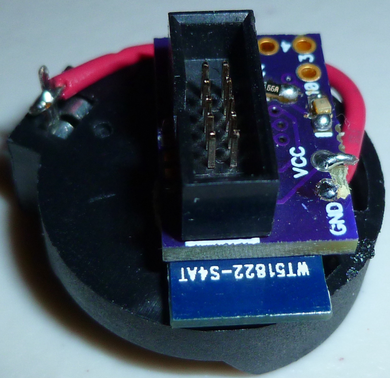
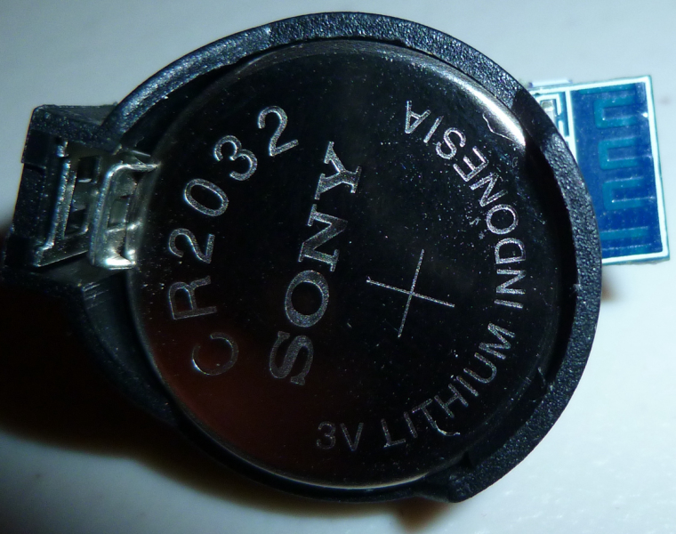
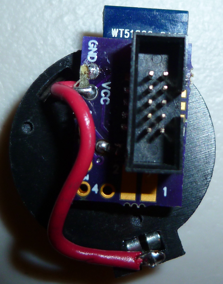
              I made a prototype of my CR2032 buttoncell project using the earlier small nRF51822-4 beakout board. I have it running the MySensors passive sensor code. It reports to the serial gatewaqy once every minute.
              0_1510229855666_cr2032_proto1.jpg

              1 Reply Last reply
              1
              • scalzS Offline
                scalzS Offline
                scalz
                Hardware Contributor
                wrote on last edited by
                #1261

                cool.
                you could add some clearance for the antenna, better I think for antenna radiation.

                NeverDieN 1 Reply Last reply
                0
                • scalzS scalz

                  cool.
                  you could add some clearance for the antenna, better I think for antenna radiation.

                  NeverDieN Offline
                  NeverDieN Offline
                  NeverDie
                  Hero Member
                  wrote on last edited by
                  #1262

                  @scalz said in nRF5 Bluetooth action!:

                  you could add some clearance for the antenna, better I think for antenna radiation.

                  0_1510243932750_cr2030_proto2.jpg
                  0_1510243941869_cr2030_proto3.jpg

                  OK, I adjusted it. How about now?

                  1 Reply Last reply
                  2
                  • ahmedadelhosniA Offline
                    ahmedadelhosniA Offline
                    ahmedadelhosni
                    wrote on last edited by
                    #1263

                    I dont have access to the source code now. Can someone please tell which pins are configured as Tx and Rx for serial communication ?

                    NeverDieN 1 Reply Last reply
                    0
                    • ahmedadelhosniA ahmedadelhosni

                      I dont have access to the source code now. Can someone please tell which pins are configured as Tx and Rx for serial communication ?

                      NeverDieN Offline
                      NeverDieN Offline
                      NeverDie
                      Hero Member
                      wrote on last edited by
                      #1264

                      @ahmedadelhosni Do you mean in general? In the general case, you can select which pins are meant for Rx and Tx using your software.

                      ahmedadelhosniA 1 Reply Last reply
                      0
                      • NeverDieN NeverDie

                        @ahmedadelhosni Do you mean in general? In the general case, you can select which pins are meant for Rx and Tx using your software.

                        ahmedadelhosniA Offline
                        ahmedadelhosniA Offline
                        ahmedadelhosni
                        wrote on last edited by
                        #1265

                        Yes I read this from the datasheet but I thought maybe MySensors defines some Pins for debugging.

                        How can I set them ? Any ApI refrences ?

                        NeverDieN d00616D 2 Replies Last reply
                        0
                        • ahmedadelhosniA ahmedadelhosni

                          Yes I read this from the datasheet but I thought maybe MySensors defines some Pins for debugging.

                          How can I set them ? Any ApI refrences ?

                          NeverDieN Offline
                          NeverDieN Offline
                          NeverDie
                          Hero Member
                          wrote on last edited by
                          #1266

                          @ahmedadelhosni said in nRF5 Bluetooth action!:

                          Yes I read this from the datasheet but I thought maybe MySensors defines some Pins for debugging.

                          How can I set them ? Any ApI refrences ?

                          Look at the source code posted at https://www.openhardware.io/view/510/CR2032-Small-Wireless-Temperature-Humidity-Sensor#tabs-source

                          It will be obvious from that.

                          1 Reply Last reply
                          1
                          • ahmedadelhosniA ahmedadelhosni

                            Yes I read this from the datasheet but I thought maybe MySensors defines some Pins for debugging.

                            How can I set them ? Any ApI refrences ?

                            d00616D Offline
                            d00616D Offline
                            d00616
                            Contest Winner
                            wrote on last edited by
                            #1267

                            @ahmedadelhosni said in nRF5 Bluetooth action!:

                            Yes I read this from the datasheet but I thought maybe MySensors defines some Pins for debugging.
                            How can I set them ? Any ApI refrences ?

                            Most NRF5 pins are freely configurable. MySensors only uses the definition of the Arduino variant. If you are not lucky with the pins defined with the Arduino board variants, you can use the ArduinoHwNRF5 board. There are examples to redefine pins.

                            This repository has the release 0.1.0 its usable and stable, but I have plans to rename the files to MyBoardNRF5 and change the g_ADigitalPinMap to the more flexible Arduino primo format in the near future. I think this is required to support NRF52840 MCUs in the future.

                            scalzS 1 Reply Last reply
                            1
                            • ahmedadelhosniA Offline
                              ahmedadelhosniA Offline
                              ahmedadelhosni
                              wrote on last edited by
                              #1268

                              Thanks both for the guiding. I will look through them.

                              1 Reply Last reply
                              0
                              • Nca78N Offline
                                Nca78N Offline
                                Nca78
                                Hardware Contributor
                                wrote on last edited by
                                #1269

                                @NeverDie how is the battery voltage doing on your existing test node ?
                                I think you should include a strong capacitor to help the battery during TX/RX sequences. It's probably less necessary on NRF5 boards, but on atmega+nrf24 a board without a 100-200µF (meaning only around half of that available with a 3V bias) capacitor has a very poor battery life.

                                NeverDieN 1 Reply Last reply
                                1
                                • Nca78N Nca78

                                  @NeverDie how is the battery voltage doing on your existing test node ?
                                  I think you should include a strong capacitor to help the battery during TX/RX sequences. It's probably less necessary on NRF5 boards, but on atmega+nrf24 a board without a 100-200µF (meaning only around half of that available with a 3V bias) capacitor has a very poor battery life.

                                  NeverDieN Offline
                                  NeverDieN Offline
                                  NeverDie
                                  Hero Member
                                  wrote on last edited by NeverDie
                                  #1270

                                  @Nca78 said in nRF5 Bluetooth action!:

                                  @NeverDie how is the battery voltage doing on your existing test node ?
                                  I think you should include a strong capacitor to help the battery during TX/RX sequences. It's probably less necessary on NRF5 boards, but on atmega+nrf24 a board without a 100-200µF (meaning only around half of that available with a 3V bias) capacitor has a very poor battery life.

                                  No real data as of yet, though I haven't noticed any problems per se. What size capacitor do you recommend?

                                  Here's why I was hoping I could maybe sidestep the issue:
                                  0_1510565830687_pulse.png
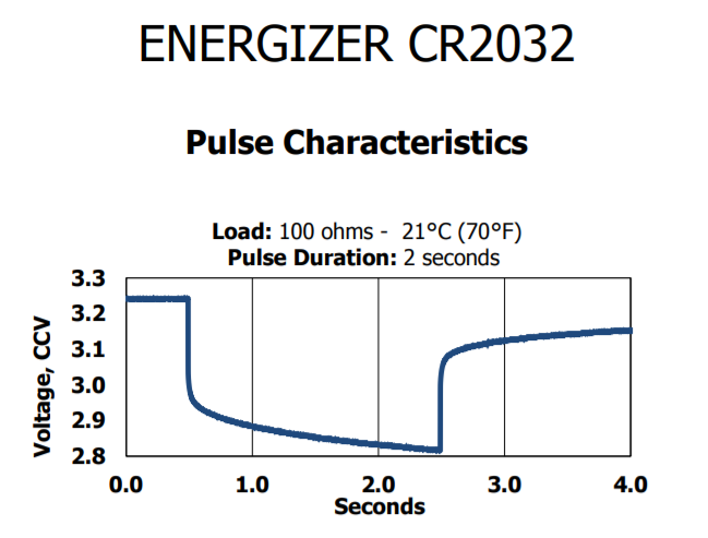
                                  http://data.energizer.com/pdfs/cr2032.pdf
                                  i.e. very short pulses might have stable voltage. I'm not sure what amount of current is assumed by that Energizer graph though.

                                  1 Reply Last reply
                                  0
                                  • d00616D d00616

                                    @ahmedadelhosni said in nRF5 Bluetooth action!:

                                    Yes I read this from the datasheet but I thought maybe MySensors defines some Pins for debugging.
                                    How can I set them ? Any ApI refrences ?

                                    Most NRF5 pins are freely configurable. MySensors only uses the definition of the Arduino variant. If you are not lucky with the pins defined with the Arduino board variants, you can use the ArduinoHwNRF5 board. There are examples to redefine pins.

                                    This repository has the release 0.1.0 its usable and stable, but I have plans to rename the files to MyBoardNRF5 and change the g_ADigitalPinMap to the more flexible Arduino primo format in the near future. I think this is required to support NRF52840 MCUs in the future.

                                    scalzS Offline
                                    scalzS Offline
                                    scalz
                                    Hardware Contributor
                                    wrote on last edited by scalz
                                    #1271

                                    @d00616 said in nRF5 Bluetooth action!:
                                    I think this is required to support NRF52840 MCUs in the future.

                                    Again, you've done a nice a work on ESB driver :+1:
                                    At least we can confirm that nrf52840 works with regular variant boards, and basic MySensors features, as it was a part of an intense traffic setup yesterday.

                                    That's the proof MySensors is getting better week after week :)

                                    1 Reply Last reply
                                    0
                                    • scalzS Offline
                                      scalzS Offline
                                      scalz
                                      Hardware Contributor
                                      wrote on last edited by scalz
                                      #1272

                                      @NeverDie
                                      I would use 100 to 200uf like said above. That's what i'm doing with all my coincell nodes too.
                                      This is regarding the internal resistance of coincells which is not great >5mA, especially when coincell will be more aged. So it is recommanded to increase lifetime.

                                      But not too strong capacitor value, else that won't be better (you don't want to waste energy, and increase internal coincell res, by charging caps, else you would need a current limiting resistor lol).

                                      I would not be too cheap by omitting decoupling and buffering capa, on my boards I prefer to have footprints (optional or not) because sure it can work well at the beginning but as soon as lifetime goes, it can change..

                                      1 Reply Last reply
                                      2
                                      • NeverDieN Offline
                                        NeverDieN Offline
                                        NeverDie
                                        Hero Member
                                        wrote on last edited by
                                        #1273

                                        Thank you @nca78 and @scalz . Per your suggestions, I added a 100uF ceramic cap to version 8 of the multi-sensor board:
                                        https://www.openhardware.io/view/510/Multi-Sensor-TempHumidity-LeakMagnetLightAccel

                                        1 Reply Last reply
                                        0
                                        • NeverDieN Offline
                                          NeverDieN Offline
                                          NeverDie
                                          Hero Member
                                          wrote on last edited by NeverDie
                                          #1274

                                          Anyone tried building a bluetooth stack on the nRF5x from within the Arduino IDE? I can see how running it simultaneously with the mySensors code would be tricky, but maybe one could switch back and forth between the two? e.g. if you want to output debug text to a terminal window on your smart phone via bluetooth If so, anyone have any demo code for doing that?

                                          For that matter, has anyone here tried the Arduino Primo? And if so, how did it go?

                                          Nca78N d00616D 2 Replies Last reply
                                          0
                                          Reply
                                          • Reply as topic
                                          Log in to reply
                                          • Oldest to Newest
                                          • Newest to Oldest
                                          • Most Votes


                                          7

                                          Online

                                          11.7k

                                          Users

                                          11.2k

                                          Topics

                                          113.0k

                                          Posts


                                          Copyright 2019 TBD   |   Forum Guidelines   |   Privacy Policy   |   Terms of Service
                                          • Login

                                          • Don't have an account? Register

                                          • Login or register to search.
                                          • First post
                                            Last post
                                          0
                                          • MySensors
                                          • OpenHardware.io
                                          • Categories
                                          • Recent
                                          • Tags
                                          • Popular