nRF5 action!
-
It's not clear whether the DK can/should be used for this part of it, as it's unclear (at least to me) whether it will end up altering the target chip or the DK. I'm just not sure. So, to do at least this ambiguous part of it, I'll first check whether or not the nRFgo studio software will work with one of the other programmers I've collected (not the DK). That may take a while...
-
@NeverDie if I remember well in the datasheet they say you have to put the softdevice on it first.
@Nca78 said in nRF5 Bluetooth action!:
@NeverDie if I remember well in the datasheet they say you have to put the softdevice on it first.
@NeverDie
you need to do this if you're using ble, it's the nordic stack running ble etc behind the scene.
For using nrf52 with MySensors, you don't need to do this. Also, MySensors & the softdevice can't run at the same time for the moment afaik.this module should work like others module, by following nrf52 datasheet.
looking at their datasheet, you maybe could add (i don't know if it's already onboard):- 100pf on DEC2
- 0.1uf on DEC1 (but they have no DEC1 1) it's already onboard, 2) there is a typo error on their datasheet ?? as DEC5 doesn't exist on nrf52)
- decoupling power
then it's just a matter of swd programming (3v,gnd,DIO,CLK)
You can take a look at nordic datasheet, or adafruit howtos are nice too.
-
@Nca78 said in nRF5 Bluetooth action!:
@NeverDie if I remember well in the datasheet they say you have to put the softdevice on it first.
@NeverDie
you need to do this if you're using ble, it's the nordic stack running ble etc behind the scene.
For using nrf52 with MySensors, you don't need to do this. Also, MySensors & the softdevice can't run at the same time for the moment afaik.this module should work like others module, by following nrf52 datasheet.
looking at their datasheet, you maybe could add (i don't know if it's already onboard):- 100pf on DEC2
- 0.1uf on DEC1 (but they have no DEC1 1) it's already onboard, 2) there is a typo error on their datasheet ?? as DEC5 doesn't exist on nrf52)
- decoupling power
then it's just a matter of swd programming (3v,gnd,DIO,CLK)
You can take a look at nordic datasheet, or adafruit howtos are nice too.
@scalz said in nRF5 Bluetooth action!:
- 0.1uf on DEC1 (but they have no DEC1 1) it's already onboard, 2) there is a typo error on their datasheet ?? as DEC5 doesn't exist on nrf52)
Great catch! Based in part on proximity to the DEC1 pins in the Ebyte datasheet, I'm guessing you've nailed it and that "DEC5" is actually DEC1.
Here's Nordic's pinout:

For other readers'convenience, here is a link (courtesy of NCA78) to Ebyte's datasheet:
https://forum.mysensors.org/assets/uploads/files/1499826952956-e73-2g4m04s_datasheet_en_v1.1.pdfBesides, as you point out, there is no actual DEC5 according to the Nordic pinout, so what else could "DEC5" be?
I've just now emailed the seller to ask this question, but for now I'll assume you've nailed it. Great work!
-
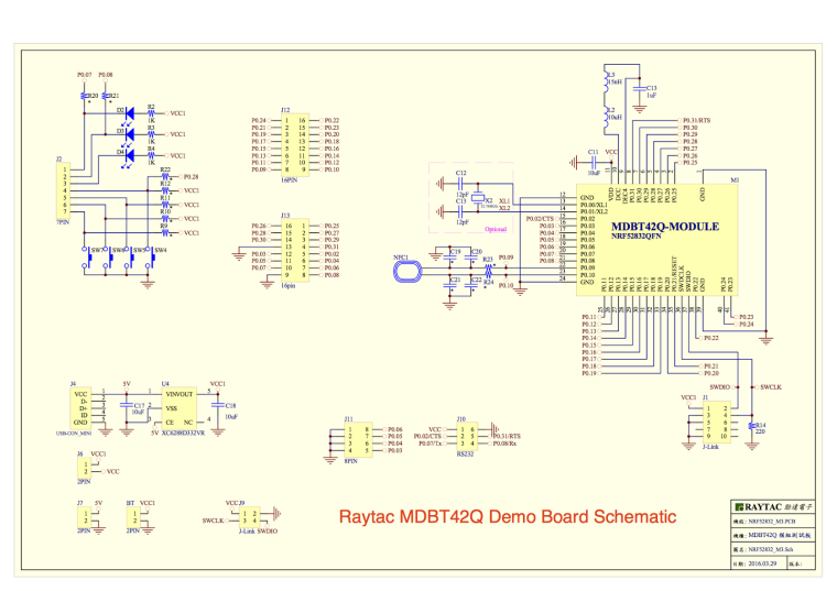
Seems as though we're somewhat shooting in the dark, though, without a schematic of what Ebyte actually did on the module. For instance, I had assumed that all this (plus whatever else is needed) had already been implemented on the Ebyte module. Relative to the Nordic nRF52832 chip size, the Ebyte moduile is already a pretty big module!
-
I'm tring to blink an led on a PCB I made not realy knowing how to program the IC before other than connection the SWD pins.
I've followed the startup guide at github flashed the soft device probably successful using the ST link V2(while flashing the soft device it blinked the on board st link V2 led and at the end the blue led on my PCB stopped being on.)
So I've got an RGB led connected to my PCB to pins:
#define RGBL_RED_PIN P0.16
#define RGBL_GREEN_PIN P0.15
#define RGBL_BLUE_PIN P0.17now for a test to see if I got it right I want to blink each of them how would I do it?
What is the arduino pin mapping?
-
Seems as though we're somewhat shooting in the dark, though, without a schematic of what Ebyte actually did on the module. For instance, I had assumed that all this (plus whatever else is needed) had already been implemented on the Ebyte module. Relative to the Nordic nRF52832 chip size, the Ebyte moduile is already a pretty big module!
@NeverDie said in nRF5 Bluetooth action!:
Seems as though we're somewhat shooting in the dark, though, without a schematic of what Ebyte actually did on the module.
On the other hand, I suppose if Ebyte had already decoupled DEC1 and DEC2 with caps on their module, there'd be no point in exposing those pins. So, I guess by inference, they must not already be decoupled. Is that the idea?
-
I'm tring to blink an led on a PCB I made not realy knowing how to program the IC before other than connection the SWD pins.
I've followed the startup guide at github flashed the soft device probably successful using the ST link V2(while flashing the soft device it blinked the on board st link V2 led and at the end the blue led on my PCB stopped being on.)
So I've got an RGB led connected to my PCB to pins:
#define RGBL_RED_PIN P0.16
#define RGBL_GREEN_PIN P0.15
#define RGBL_BLUE_PIN P0.17now for a test to see if I got it right I want to blink each of them how would I do it?
What is the arduino pin mapping?
@Mike_Lemo said in nRF5 Bluetooth action!:
I'm tring to blink an led on a PCB I made not realy knowing how to program the IC before other than connection the SWD pins.
I've followed the startup guide at github flashed the soft device probably successful using the ST link V2(while flashing the soft device it blinked the on board st link V2 led and at the end the blue led on my PCB stopped being on.)
So I've got an RGB led connected to my PCB to pins:
#define RGBL_RED_PIN P0.16
#define RGBL_GREEN_PIN P0.15
#define RGBL_BLUE_PIN P0.17now for a test to see if I got it right I want to blink each of them how would I do it?
What is the arduino pin mapping?
Isn't the arduino mapping generally handled by the boards.txt file? Which board that you're using are you telling the compiler that it is? i.e. which board under the board manager in the Arduino IDE are you selecting?
-
Actually never mind I got it just removed the P0. and put the number for example if I want to flash P0.16 I do 16 and it works!!
Feels so good to understand that I can now finish my big project now all I have to figure out it how to use NFC and connect it to another NRF52832 device!Here's a demo:
https://www.youtube.com/watch?v=hCMKsORq2sM&feature=youtu.be
-
@Mike_Lemo said in nRF5 Bluetooth action!:
I'm tring to blink an led on a PCB I made not realy knowing how to program the IC before other than connection the SWD pins.
I've followed the startup guide at github flashed the soft device probably successful using the ST link V2(while flashing the soft device it blinked the on board st link V2 led and at the end the blue led on my PCB stopped being on.)
So I've got an RGB led connected to my PCB to pins:
#define RGBL_RED_PIN P0.16
#define RGBL_GREEN_PIN P0.15
#define RGBL_BLUE_PIN P0.17now for a test to see if I got it right I want to blink each of them how would I do it?
What is the arduino pin mapping?
Isn't the arduino mapping generally handled by the boards.txt file? Which board that you're using are you telling the compiler that it is? i.e. which board under the board manager in the Arduino IDE are you selecting?
-
Aha! I just now noticed that on the silk screen for the actual module itself, it does indeed say DEC1, not DEC5, in what would otherwise be the DEC5 location. So, that settles it. "DEC5" really is DEC1, and "DEC5" is just a typo in the datasheet. :)
-
@Mike_Lemo said in nRF5 Bluetooth action!:
Oh yeah and forgot to mention I used the generic NRF52 settings.
The "generic" settings haven't a good pin assignment. Pins P0.00 and P0.01 are reserved for the 32KHz crystal and defined as TX/RX pins. That's an conflict.
-
@Mike_Lemo said in nRF5 Bluetooth action!:
Oh yeah and forgot to mention I used the generic NRF52 settings.
The "generic" settings haven't a good pin assignment. Pins P0.00 and P0.01 are reserved for the 32KHz crystal and defined as TX/RX pins. That's an conflict.
@d00616 said in nRF5 Bluetooth action!:
@Mike_Lemo said in nRF5 Bluetooth action!:
Oh yeah and forgot to mention I used the generic NRF52 settings.
The "generic" settings haven't a good pin assignment. Pins P0.00 and P0.01 are reserved for the 32KHz crystal and defined as TX/RX pins. That's an conflict.
What should we use instead?
-
@NeverDie The "Taida Century nRF52 minidev" has a lot of pins mapped out:
https://github.com/RIOT-OS/RIOT/wiki/Board%3A-nRF52-minidev you can select the programmer like your needs. The RedBear BLE Blend 2 has also a lot of pins mapped out, but the CMSIS-DAP is preselected. -
@NeverDie The "Taida Century nRF52 minidev" has a lot of pins mapped out:
https://github.com/RIOT-OS/RIOT/wiki/Board%3A-nRF52-minidev you can select the programmer like your needs. The RedBear BLE Blend 2 has also a lot of pins mapped out, but the CMSIS-DAP is preselected. -
@Mike_Lemo said in nRF5 Bluetooth action!:
@d00616 It says there NFC is not useable but what if my board is NFC hardware ready? how would I use that?
It's simple. Use that. NFC isn't enabled or disabled by the board definition. Without SoftDevice, you have to enable the NFC functionality by flashing into the UICR.
You can define your own Board. Look into the "boards.txt" file and the "variants" folder in ~/.arduino15/packages/sandeepmistry/hardware/nRF5/0.3.0/ Most pins can be assigned to roles like SPI, I2C, UART.... Pins like NFC, RESET are fixed and analog Pins an be ordered like your needs.
-
@Mike_Lemo said in nRF5 Bluetooth action!:
I'm tring to blink an led on a PCB I made not realy knowing how to program the IC before other than connection the SWD pins.
I've followed the startup guide at github flashed the soft device probably successful using the ST link V2(while flashing the soft device it blinked the on board st link V2 led and at the end the blue led on my PCB stopped being on.)
So I've got an RGB led connected to my PCB to pins:
#define RGBL_RED_PIN P0.16
#define RGBL_GREEN_PIN P0.15
#define RGBL_BLUE_PIN P0.17now for a test to see if I got it right I want to blink each of them how would I do it?
What is the arduino pin mapping?
Isn't the arduino mapping generally handled by the boards.txt file? Which board that you're using are you telling the compiler that it is? i.e. which board under the board manager in the Arduino IDE are you selecting?
-
@Mike_Lemo said in nRF5 Bluetooth action!:
@d00616 It says there NFC is not useable but what if my board is NFC hardware ready? how would I use that?
It's simple. Use that. NFC isn't enabled or disabled by the board definition. Without SoftDevice, you have to enable the NFC functionality by flashing into the UICR.
You can define your own Board. Look into the "boards.txt" file and the "variants" folder in ~/.arduino15/packages/sandeepmistry/hardware/nRF5/0.3.0/ Most pins can be assigned to roles like SPI, I2C, UART.... Pins like NFC, RESET are fixed and analog Pins an be ordered like your needs.
-
@Mike_Lemo said in nRF5 Bluetooth action!:
@NeverDie where can that boards.txt file of the NRF52 thing be found?
On the Windows platform it's located in this directory: Program Files/Arduino/hardware/arduino/avr
-
@Mike_Lemo said in nRF5 Bluetooth action!:
@NeverDie where can that boards.txt file of the NRF52 thing be found?
On the Windows platform it's located in this directory: Program Files/Arduino/hardware/arduino/avr