nRF5 action!
-
I have found a simple way to mass erase the MCU. Select "None" as SoftDevice and use the "Burn Bootloader" function. There is an error generated but the device is erased.
-
@mtiutiu said in nRF5 Bluetooth action!:
I'm going to try this one too when I have time wt51822-s4at
I used your link to order some of those modules just now. They're so small and cheap that they might be nice for simple things.
With the Ebyte module now working, I'm feeling emboldened again. :)
-
Which nRF52832 pins do I use for the mysensors implementation of UART Tx and Rx on the nRF52832? When I looked in Nordic's nRF52832 datasheet (http://infocenter.nordicsemi.com/pdf/nRF52832_PS_v1.3.pdf), I didn't see any pins specifically assigned/reserved for that purpose.
-
by default nrf52dk is RX(24) and TX(25).
for adafruit, i have not installed the board..but you can check in adafruit howto (or in their variant files).Peripherals are not fixed, that's a big advantage vs simple 8bits mcu. You define them when doing your design (sometimes it may need some checks in datasheet, depends on mcu).
So, for your ebyte module your options are:
- create a new board for the board manager (see variant files) regarding a specific design.
- or you don't care of this for the moment, and you can simply use nrf52dk board and use the same mapping.
- or, in the same order, use adafruit board and their mapping (or sparkfun board etc.., no matter, just check their board map pictures )
@scalz said in nRF5 Bluetooth action!:
So, for your ebyte module your options are:
I working on the fourth option, I publish soon:
- Define the pin mapping in your sketch, then its part of your code
Like @scalz has written. Place the MCU in your layout and define the pin mapping later. Exceptions are analog pins, comparator pins , NFC pins, reset... The pins are documented in Infocenter: Pin assignments Please look at the "GPIO usage restrictions" chapter too.
-
@mtiutiu said in nRF5 Bluetooth action!:
I'm going to try this one too when I have time wt51822-s4at
I used your link to order some of those modules just now. They're so small and cheap that they might be nice for simple things.
With the Ebyte module now working, I'm feeling emboldened again. :)
-
For the ebyte nrf52832 based modules did you had to wire some external components? Are there some other requirements for it in order to work?
Thanks.
@mtiutiu said in nRF5 Bluetooth action!:
For the ebyte nrf52832 based modules did you had to wire some external components? Are there some other requirements for it in order to work?
Thanks.
For proof of concept purposes, I had just 4 wires connected for programming: PWR, GND, SWDIO, and SWDCLK. After programming for range testing: just PWR and GND. I'll soon be adding UART Tx so that I can also read its serial console output.
-
by default nrf52dk is RX(24) and TX(25).
for adafruit, i have not installed the board..but you can check in adafruit howto (or in their variant files).Peripherals are not fixed, that's a big advantage vs simple 8bits mcu. You define them when doing your design (sometimes it may need some checks in datasheet, depends on mcu).
So, for your ebyte module your options are:
- create a new board for the board manager (see variant files) regarding a specific design.
- or you don't care of this for the moment, and you can simply use nrf52dk board and use the same mapping.
- or, in the same order, use adafruit board and their mapping (or sparkfun board etc.., no matter, just check their board map pictures )
@scalz
Thanks for the explanation. I had been programming it as a "Generic nRF82832," and I don't know what that mapping is. However, I can just as easily pick one of the alternatives you listed, such as the D.K, to get a predictable pin mapping.@d00616
Your idea of having the pin mapping be selectable within the sketch sounds great! A+. I'm really looking forward to that and hope that you can do it soon. It sounds much easier for noobs like me than having to futz about with finding/changing/installing other files, and maybe also making it easier to share with and/or borrow from other makers. -
Not related to Bluetooth but @NeverDie did you also receive small antennas and ipx->sma adapters with your modules ?
I received one for each nrf52 and also one for the pa lna nrf24. I was not expecting them as those modules all have a PCB antenna and ipx is just an option. -
Not related to Bluetooth but @NeverDie did you also receive small antennas and ipx->sma adapters with your modules ?
I received one for each nrf52 and also one for the pa lna nrf24. I was not expecting them as those modules all have a PCB antenna and ipx is just an option.@Nca78 said in nRF5 Bluetooth action!:
did you also receive small antennas and ipx->sma adapters with your modules ?
Nope.
-
by default nrf52dk is RX(24) and TX(25).
for adafruit, i have not installed the board..but you can check in adafruit howto (or in their variant files).Peripherals are not fixed, that's a big advantage vs simple 8bits mcu. You define them when doing your design (sometimes it may need some checks in datasheet, depends on mcu).
So, for your ebyte module your options are:
- create a new board for the board manager (see variant files) regarding a specific design.
- or you don't care of this for the moment, and you can simply use nrf52dk board and use the same mapping.
- or, in the same order, use adafruit board and their mapping (or sparkfun board etc.., no matter, just check their board map pictures )
@scalz said in nRF5 Bluetooth action!:
nrf52dk is RX(24) and TX(25)
Hmm.. Where is that defined exactly? I just now tried hooking the Tx(25) of an actual nrf52DK to the Rx pin of a FTDI connector, and GND to GND, but I'm not seeing any output from the nrf52DK, even though I should be. I'm assuming that by 25 you're referring to PO.25 and not pin 25 on the chip?
-
I googled up this diagram:
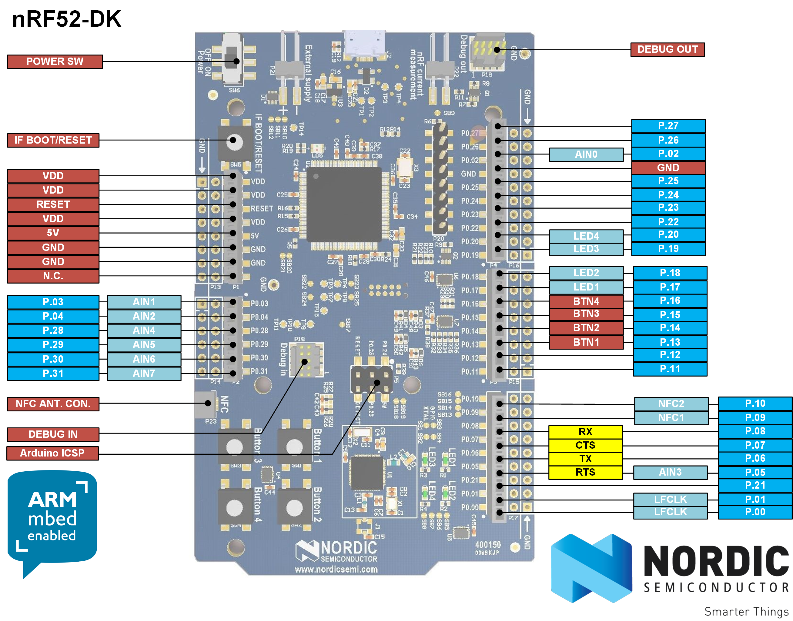
Looks as though TX is maybe P0.06. I'll try that.... -
Confirmed: Pin P0.06 works as Uarte TX on the nRF52 DK. :)
-
As final confirmation I did re-program the Ebyte module as an nRF52 DK, then connected its P0.06 to the FTDI RX, and, voilà , it worked as expected. @scalz Thanks for the idea! :)
One small caveat: On the Ebyte module, P0.06 doesn't appear on the silkscreen (there's a typo where it's shown as P0.07 instead, resulting in there being two P0.07's on the silkscreen), so just pick the most obvious pin based on the numerical progression (or else consult the datasheet), and it will work.
-
In lieu of my breakout board, which hasn't yet arrived, I've been attaching wires directly to the module so that I can do more than just sit and wait for the BoB delivery. I'm now doing it this way:
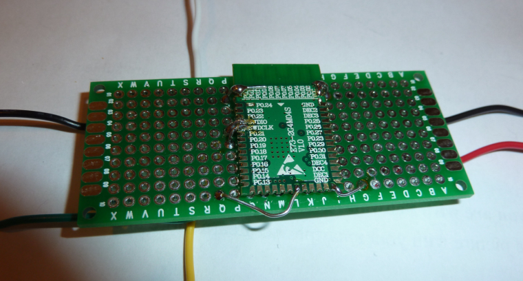
and although crude it's working much better than just soldering the wire to the module with no mechanical support. Doing it the way pictured, the connections stay connected and don't break loose. :) Ironically, by the time my breakout boards finally do arrive, I may have already learned everything I needed them for.I am curious: how are the rest of you handling this issue?
[Edit: One other alternative: once my 1.27mm pitch generic protoboards arrive, I expect they'll offer up cleaner connection possibilities. At the moment, I'm also waiting for them to arrive from Aliexpress....]
-
@scalz
Thanks for the explanation. I had been programming it as a "Generic nRF82832," and I don't know what that mapping is. However, I can just as easily pick one of the alternatives you listed, such as the D.K, to get a predictable pin mapping.@d00616
Your idea of having the pin mapping be selectable within the sketch sounds great! A+. I'm really looking forward to that and hope that you can do it soon. It sounds much easier for noobs like me than having to futz about with finding/changing/installing other files, and maybe also making it easier to share with and/or borrow from other makers.@NeverDie said in nRF5 Bluetooth action!:
Your idea of having the pin mapping be selectable within the sketch sounds great! A+. I'm really looking forward to that and hope that you can do it soon.
With merging this pull request the feature should be available: https://github.com/mysensors/ArduinoBoards/pull/13
Documentation can be found at https://github.com/mysensors/ArduinoHwNRF5
-
@NeverDie said in nRF5 Bluetooth action!:
Your idea of having the pin mapping be selectable within the sketch sounds great! A+. I'm really looking forward to that and hope that you can do it soon.
With merging this pull request the feature should be available: https://github.com/mysensors/ArduinoBoards/pull/13
Documentation can be found at https://github.com/mysensors/ArduinoHwNRF5
@d00616 said in nRF5 Bluetooth action!:
With merging this pull request the feature should be available: https://github.com/mysensors/ArduinoBoards/pull/13
Merged. Have fun with board definition in your sketch.
-
In lieu of my breakout board, which hasn't yet arrived, I've been attaching wires directly to the module so that I can do more than just sit and wait for the BoB delivery. I'm now doing it this way:
and although crude it's working much better than just soldering the wire to the module with no mechanical support. Doing it the way pictured, the connections stay connected and don't break loose. :) Ironically, by the time my breakout boards finally do arrive, I may have already learned everything I needed them for.I am curious: how are the rest of you handling this issue?
[Edit: One other alternative: once my 1.27mm pitch generic protoboards arrive, I expect they'll offer up cleaner connection possibilities. At the moment, I'm also waiting for them to arrive from Aliexpress....]
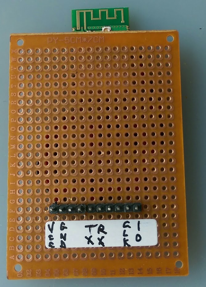
@NeverDie said in nRF5 Bluetooth action!:
I am curious: how are the rest of you handling this issue?
Not many solutions, I soldered wires directly to the modules too, I used thin&cheap wires from aliexpress. They are very convenient for this, easy to solder and very soft so not having any constraint on the solder joints when you manipulate them. Then I put module on the side of board with double sided tape and soldered other ends of the wires to a connector.
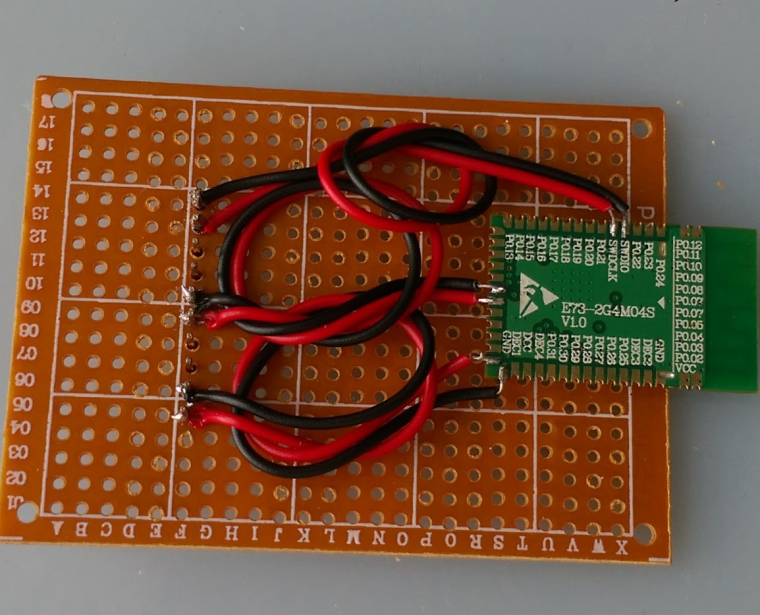
Then I flip everything and only look at the beautiful side of things :D
-
@d00616 said in nRF5 Bluetooth action!:
With merging this pull request the feature should be available: https://github.com/mysensors/ArduinoBoards/pull/13
Merged. Have fun with board definition in your sketch.
@d00616 said in nRF5 Bluetooth action!:
@d00616 said in nRF5 Bluetooth action!:
With merging this pull request the feature should be available: https://github.com/mysensors/ArduinoBoards/pull/13
Merged. Have fun with board definition in your sketch.
Thanks! By being "merged," does that mean it is now in the regular MySensors development release, and so I should reload a fresh copy of the MySensors development library?
Also, is this the way I should enable P0.21 as nReset (to enable hardware resets on P0.21), or should I instead be writing 0xFFFF directly to both the PSELRESET[0] and PSELRESET[1] registers to enable that?