nRF5 action!
-
Good news. It appears that DCDC is already implemented on the Ebyte nRF52832 and working automatically!
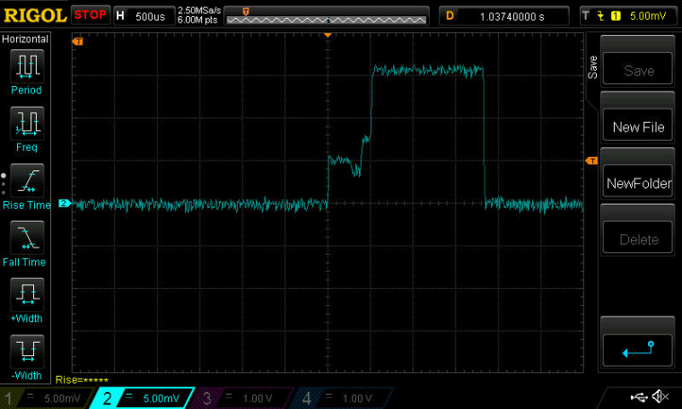
Just for grins, I decided to measure the Tx time and current draw from sending a 13 byte payload in a packet, and I was happily surprised to see how low the current draw was:
The yellow trace marks the start and stop of the packet transmission process from a software point of view, but the blue trace measures the current (as before 1mv=1ma). As you can see, the transmission current never seems to rise above 2.5ma. The only (?) explanation I can think of is that DCDC must be working. Right? Tx power is set to be 4dbm.
It would be great if someone else would confirm/refute the measurement.
@NeverDie said in nRF5 Bluetooth action!:
It would be great if someone else would confirm/refute the measurement.
I don't think it's possible, from the datasheet peak current is 7.7mA at +4dB with DCDC enabled with 3V power supply.
Current gain from 3V=>1.7V DCDC conversion is already included in this measurement so you should not be able to go lower.How did you make your measurement across the resistor ?
-
@NeverDie said in nRF5 Bluetooth action!:
It would be great if someone else would confirm/refute the measurement.
I don't think it's possible, from the datasheet peak current is 7.7mA at +4dB with DCDC enabled with 3V power supply.
Current gain from 3V=>1.7V DCDC conversion is already included in this measurement so you should not be able to go lower.How did you make your measurement across the resistor ?
@Nca78
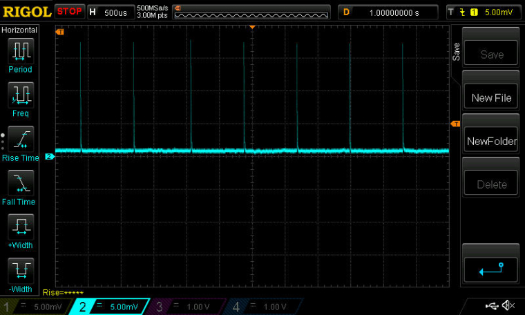
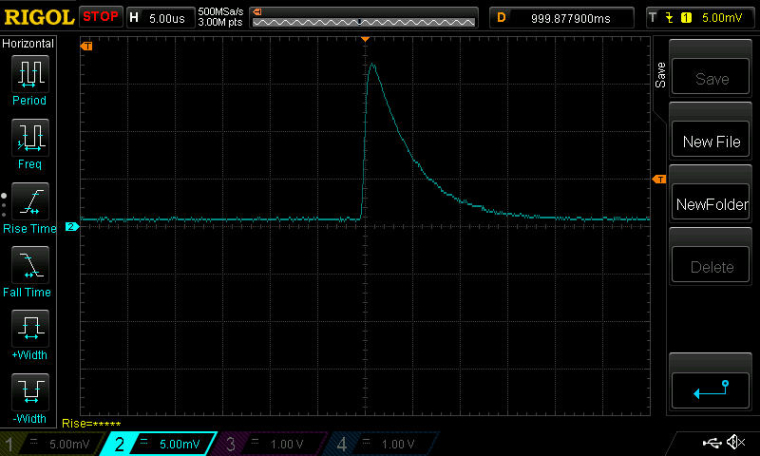
You're right. It didn't ring true, so I setup some different capture hardware, and this time the image is a lot crisper:
This time I powered it from a 3.3v supercap and with the 1 ohm resistor soldered securely onto a PCB, with the o-scope leads on either side of it.So, sadly, it doesn't look DCDC after all, because on this capture the peak is exceeding 20ma. :(
It's interesting how lengthy (and energy intensive) the phase is that's just prior to the transmission itself. I presume that's mainly just the PLL coming up to speed? It looks as though the actual current expended in the prelude exceeds that of the actual Tx proper!
I'm guessing that in the earlier scope capture, the probe must have slipped into 10x mode, because the shape is similar, just proportionately reduced by roughly that factor.
-
BTW, I assembled my third board now, and it sleeps at about 9.9ua. The first one sleeps at about 6ua, and the second at about 9ua. It would be interesting to know why the first board is so much less, but it seems that about 9-10ua is the more typical number. That also seems to agree with @d00616 's measurements.
-
Interestingly enough, you can put the radio into receive mode and then sleep the mcu with the radio still in receive mode. Here's a screenshot of current consumption while receiving, where I alternate between leaving the mcu active or sleeping it (each for duration of 500ms). In-between, I sleep everything (both radio and mcu) for 1 second:
-
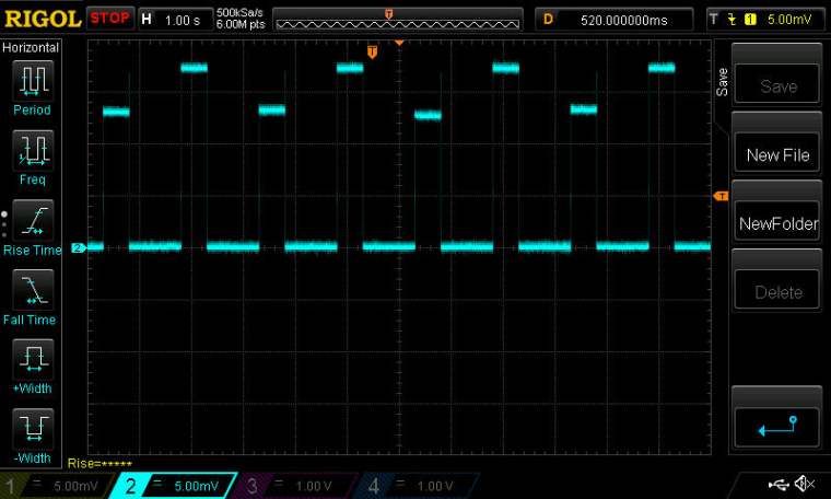
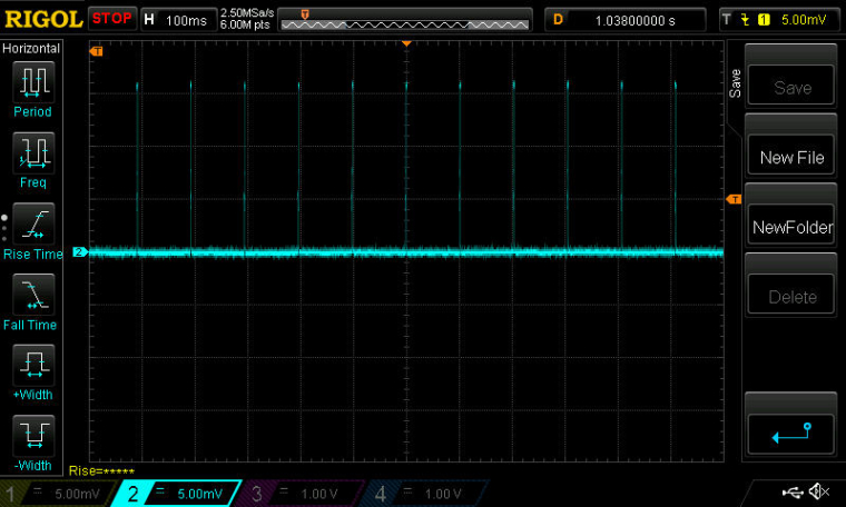
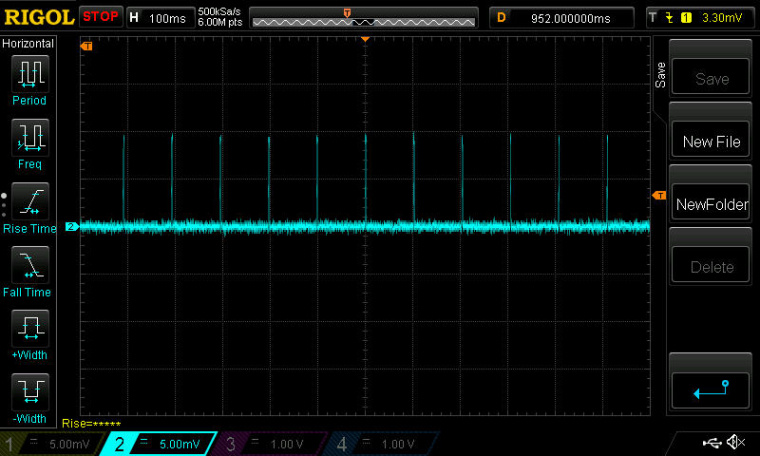
Here's the mode that I'm most interested in: Putting the radio into Rx for about 1ms per 100ms interval to listen for remote commands. The rest of the time everthing (both radio and mcu) are in deep sleep waiting for the RTC to wake them up.
Here's a close-up of the current drawn during that roughly 1ms interval:
I ran this just now, and my solar setup can easily handle this load during the daytime, even from deep indoors far from the windows. This was the scenario that really stressed the RFM69+atmega328p combo when I tried doing it using the RFM69's listen mode. I'll see tonight how the 10F supercap handles the load without any solar assist. :)
Because of the nRF52839's 2Mbps datarate, I can probably cut the listen window down substantially from 1ms to much less (much less than would be possible with an RFM69, due to its maximum of 300kbps datarate), but for ease of programming I'm starting with this.
-
Here's the mode that I'm most interested in: Putting the radio into Rx for about 1ms per 100ms interval to listen for remote commands. The rest of the time everthing (both radio and mcu) are in deep sleep waiting for the RTC to wake them up.
Here's a close-up of the current drawn during that roughly 1ms interval:
I ran this just now, and my solar setup can easily handle this load during the daytime, even from deep indoors far from the windows. This was the scenario that really stressed the RFM69+atmega328p combo when I tried doing it using the RFM69's listen mode. I'll see tonight how the 10F supercap handles the load without any solar assist. :)
Because of the nRF52839's 2Mbps datarate, I can probably cut the listen window down substantially from 1ms to much less (much less than would be possible with an RFM69, due to its maximum of 300kbps datarate), but for ease of programming I'm starting with this.
@NeverDie said in nRF5 Bluetooth action!:
Here's the mode that I'm most interested in: Putting the radio into Rx for about 1ms per 100ms interval to listen for remote commands. The rest of the time everthing (both radio and mcu) are in deep sleep waiting for the RTC to wake them up.
When you take a look into the PPI section, you are able to let the CPU sleep until a radio packet is received. With PPI, the listen mode can be activated and deactivated without CPU interaction.
The nRF5 MCUs are able to to a lot of things without waking up the CPU. That's a really cool feature.
-
@NeverDie said in nRF5 Bluetooth action!:
Here's the mode that I'm most interested in: Putting the radio into Rx for about 1ms per 100ms interval to listen for remote commands. The rest of the time everthing (both radio and mcu) are in deep sleep waiting for the RTC to wake them up.
When you take a look into the PPI section, you are able to let the CPU sleep until a radio packet is received. With PPI, the listen mode can be activated and deactivated without CPU interaction.
The nRF5 MCUs are able to to a lot of things without waking up the CPU. That's a really cool feature.
@d00616 said in nRF5 Bluetooth action!:
@NeverDie said in nRF5 Bluetooth action!:
Here's the mode that I'm most interested in: Putting the radio into Rx for about 1ms per 100ms interval to listen for remote commands. The rest of the time everthing (both radio and mcu) are in deep sleep waiting for the RTC to wake them up.
When you take a look into the PPI section, you are able to let the CPU sleep until a radio packet is received. With PPI, the listen mode can be activated and deactivated without CPU interaction.
The nRF5 MCUs are able to to a lot of things without waking up the CPU. That's a really cool feature.
Sounds like it has potential. Any demo code for this? The datasheet seems a bit sketchy.
-
@d00616 said in nRF5 Bluetooth action!:
@NeverDie said in nRF5 Bluetooth action!:
Here's the mode that I'm most interested in: Putting the radio into Rx for about 1ms per 100ms interval to listen for remote commands. The rest of the time everthing (both radio and mcu) are in deep sleep waiting for the RTC to wake them up.
When you take a look into the PPI section, you are able to let the CPU sleep until a radio packet is received. With PPI, the listen mode can be activated and deactivated without CPU interaction.
The nRF5 MCUs are able to to a lot of things without waking up the CPU. That's a really cool feature.
Sounds like it has potential. Any demo code for this? The datasheet seems a bit sketchy.
@NeverDie said in nRF5 Bluetooth action!:
@d00616 said in nRF5 Bluetooth action!:
@NeverDie said in nRF5 Bluetooth action!:
Here's the mode that I'm most interested in: Putting the radio into Rx for about 1ms per 100ms interval to listen for remote commands. The rest of the time everthing (both radio and mcu) are in deep sleep waiting for the RTC to wake them up.
When you take a look into the PPI section, you are able to let the CPU sleep until a radio packet is received. With PPI, the listen mode can be activated and deactivated without CPU interaction.
The nRF5 MCUs are able to to a lot of things without waking up the CPU. That's a really cool feature.Sounds like it has potential. Any demo code for this? The datasheet seems a bit sketchy.
These are some snippets of the radio code. There are fully useable PPI and some predefined. For fully useable PPI into the EEP register, you put the address of an EVENT register and in the TEP register, you put the pointer to an TASK register.
   /** Configure PPI (Programmable peripheral interconnect) */
    // Start timer on END event
    NRF_PPI->CH[NRF5_ESB_PPI_TIMER_START].EEP = (uint32_t)&NRF_RADIO->EVENTS_END;
    NRF_PPI->CH[NRF5_ESB_PPI_TIMER_START].TEP = (uint32_t)&NRF5_RADIO_TIMER->TASKS_START;
    // Disable Radio after CC[0]
    NRF_PPI->CH[NRF5_ESB_PPI_TIMER_RADIO_DISABLE].EEP = (uint32_t)&NRF5_RADIO_TIMER->EVENTS_COMPARE[0];
    NRF_PPI->CH[NRF5_ESB_PPI_TIMER_RADIO_DISABLE].TEP = (uint32_t)&NRF_RADIO->TASKS_DISABLE;
    ...
    // Set PPI
     NRF_PPI->CHENSET = NRF5_ESB_PPI_BITS;
    ...
  // Clear PPI
    NRF_PPI->CHENCLR = NRF5_ESB_PPI_BITS;
Then you have to enable or disable the register. It could be necessary to reset the events. You can use the NRF_RESET_EVENT macro to do this job.
NRF_RESET_EVENT(NRF5_RADIO_TIMER->EVENTS_COMPARE[0]); -
I have a brute force version of "listen mode" working using just the libraries, but I have to re-initialize the radio after each cycle because it appears to lose its settings every time I sleep it.
Anyway, finding a way to add DCDC mode to these modules will probably have the biggest near-term impact on current consumption. That said, I'm sure plenty of energy savings can also be found by honing the code.
-
Comparing Figures 169 and 170 in the nRF52832 datasheet, it looks as though simply adding two inductors in series between DCC and DEC4 should be all that's needed to provide the needed hardware support for DC/DC. Looks as though the 10uH inductor also needs to be able to support a minimum of 50ma, according to the BOM (Table 145).
So, is it as simple as that together with enabling register DCDCEN? Or, is there anything more to it?
-
Yes. This is like that. I use 2 inductors (better) in serie. Why more complicated ;)
-
Actually, even just sleeping the MCU with a simple command like:
sleep(100);is apparently enough to require a re-init of the radio afterward. Not sure why that would be.
@NeverDie said in nRF5 Bluetooth action!:
Actually, even just sleeping the MCU with a simple command like:
sleep(100);is apparently enough to require a re-init of the radio afterward. Not sure why that would be.
sleep() deinitializes the transport with transportDisable(). This results in power down the radio.
At the moment I review the ESB code. I think the nRF5 is 12-13µs after an nRF24 in RX mode and 432µs before an nRF24 in TX. This can result in unstable connections when debug messages are disabled.
-
Sort-of working. Here's a screen shot with the DC/DC modification. Compare to the earlier one above:
Probably non-optimal placement of the inductors: between the DCC and DEC4 pins on my breakout board for the nRF52832.This is reason enough to do an new version of the breakout for the Ebyte module to improve the inductor positioning.
Here's the enable code:
NRF_POWER->DCDCEN=1; //enable the DCDC voltage regulator as the default.If it's this easy, I'm just surprised that the module makers haven't included it. The difference in build cost is de minimus, but the difference in delivered value is huge.
Also, it sounds like I'll have to write a variant of sleep that sleeps just the MPU while leaving the radio in receive mode. That's an easy win to improve the current consumption.
-
Good news! I went back and re-rechecked using an un-modified Ebyte module, and, indeed, this time I'm sure that the DCDC inductors are already on it! What follows is the proof. Here is the current drawn when the above DCDCEN is enabled on an unmodified Ebyte module: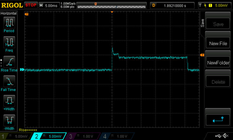
Now, here is the current drawn with the exact same script on the exact same unmodified Ebyte module, but with the DCDCEN line of code commented out: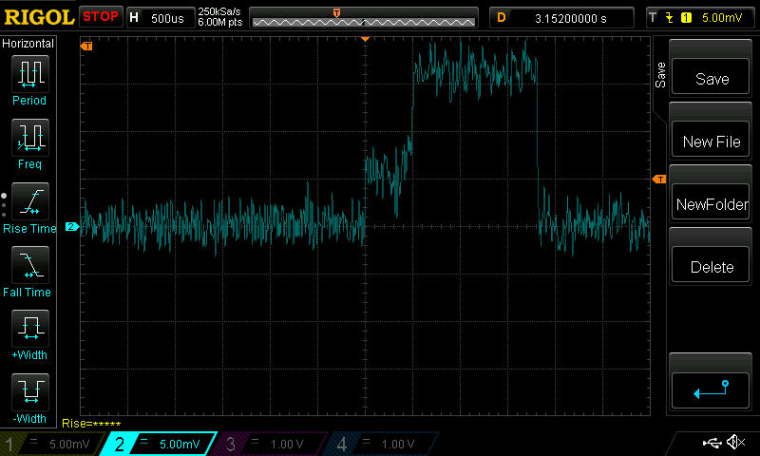
QED.
As you can see, the savings in current consumption are considerable with the DCDC enabled![Edit: although looking at it again, the timescale seems way off. Argh. Something still isn't right.] -
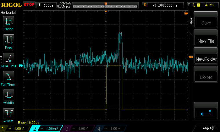
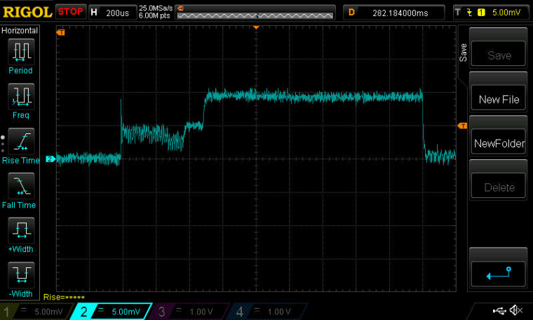
Scratch the preceeding post. I redid it more carefully this time, and I believe it confirms that the Ebyte module does not have the two inductors required for DC/DC mode.
Here is the current drawn by an unmodified Ebyte nRF52832 module which is programmed to be receiving for about 1.5ms every 100ms:
-
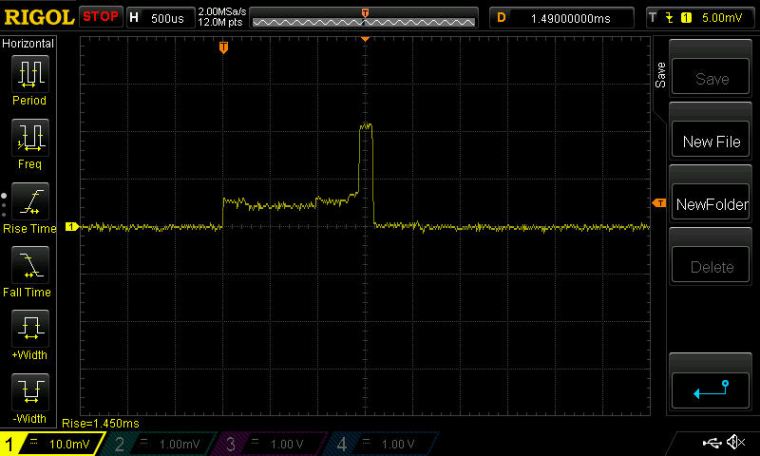
Here is what happens with exactly the same hardware (no inductors yet added), but with DCDCEN enabled:
It basically seems caught in a boot loop. -
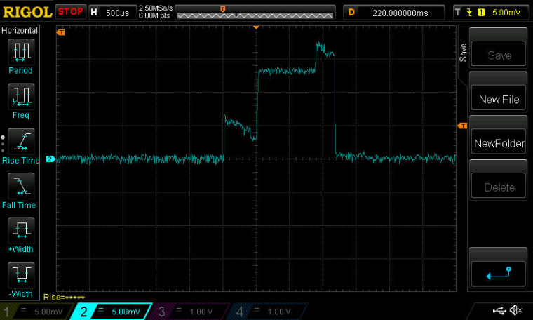
Now, adding the two inductors between DCC and DEC4, and re-measuring, we get:
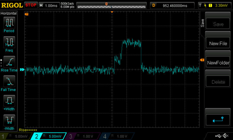
No less importantly, it does receive and decode packets!
Conclusion: Ebyte nRF52832 modules don't come with the DC/DC inductors already installed. However, they can be added, resulting in some current reduction.
-
I've baked these findings into a new breakout board for the Ebyte nRF52832:
https://www.openhardware.io/view/471
The new breakout board will enable the module to work in DC/DC mode. -
I may have found a clue as to why the reset pin (pin0.21) on the nRF52832 isn't working.
On the nRF52832 DK, I read the following register values:
PSELRESET[0]=21
PSELRESET[1]=21which is as expected. However, on the Ebyte nRF52832 module, I read those register values as:
PSELRESET[0]=4294967295
PSELRESET[1]=4294967295which makes no sense. The values match, but they don't correspond to a pin number that can represent RESET.
These two registers are described in the nRF52832 datasheet.