nRF5 action!
-
Whenever I use:
#include <MySensors.h>on the nRF52832, there is around a 10 second delay between the end of "void startup()" and the beginning of "loop()". Why is that, and what is the MySensors library doing during that interval?
-
@NeverDie said in nRF5 Bluetooth action!:
If your goal is to minimize the RX-on time, then you can trigger the RX start and stop by a timer for your minimal window where the frame must be start. Then use the bitcounter top stop the timer in case a packet is received. A shortcut to the end is disabling the RX mode. You can wakeup the CPU with the END event.P.S.: you can reduce the RX/TX time by enabling fast ramp up in MODECNF0 if you haven't to care about nRF51 compatibility.
@d00616 said in nRF5 Bluetooth action!:
P.S.: you can reduce the RX/TX time by enabling fast ramp up in MODECNF0 if you haven't to care about nRF51 compatibility.
Thanks for the tip. I tried it both ways. The first scope capture below is taken without MODECNF0 enabled on bit 0, and the second is with it enabled on bit 0.
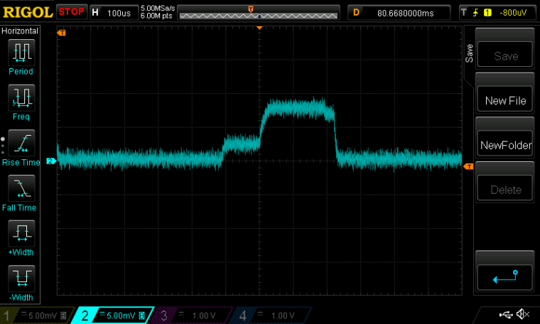
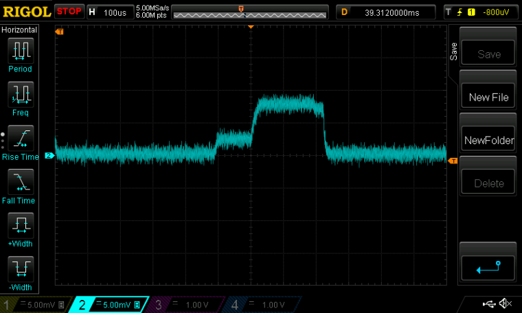
I don't really see any difference. Do you?
Scale: 1mv=1ma. Scope captures of current drawn.Maybe @jokgi can comment? His bio says he's a Senior Field Application Engineer at Nordic Semiconductor.
Maybe he sees (or knows) something that's not apparent about the fast ramp enable bit? -
Whenever I use:
#include <MySensors.h>on the nRF52832, there is around a 10 second delay between the end of "void startup()" and the beginning of "loop()". Why is that, and what is the MySensors library doing during that interval?
@NeverDie said in nRF5 Bluetooth action!:
Whenever I use:
#include <MySensors.h>on the nRF52832, there is around a 10 second delay between the end of "void startup()" and the beginning of "loop()". Why is that, and what is the MySensors library doing during that interval?
As an alternative, you can define '#define MY_CORE_ONLY' and use ' transportInit(); transportSetAddress(MY_NODE_ID);' to initialize the radio. This dosn't work at the moment with the nRF5. I'm currently looking what the reason is. All radio registers are equal when it's initialized after MySensors normal and my setup(). It's not able to send or receive packages.
Maybe someone has an idea about the reason. Here is my code for nRF5 and other with nRF24.
// Undefine to work in gateway mode #define MY_CORE_ONLY #define MY_NODE_ID (0) // Enable debug #define MY_DEBUG #define MY_DEBUG_VERBOSE_RF24 #define MY_DEBUG_VERBOSE_NRF5_ESB // Enable and select radio type attached #ifndef ARDUINO_ARCH_NRF5 #define MY_RADIO_NRF24 #else #define MY_RADIO_NRF5_ESB #include <nrf.h> #endif //#define MY_RADIO_RFM69 //#define MY_RADIO_RFM95 //#define MY_OTA_LOG_SENDER_FEATURE //#define MY_OTA_LOG_RECEIVER_FEATURE #ifndef MY_CORE_ONLY #define MY_GATEWAY_SERIAL #endif #include <MySensors.h> void state() { #ifdef ARDUINO_ARCH_NRF5 Serial.println("----------------------------------"); Serial.print("NRF_RADIO->STATE "); Serial.println(NRF_RADIO->STATE, HEX); Serial.print("NRF_RADIO->EVENTS_READY "); Serial.println(NRF_RADIO->EVENTS_READY, HEX); Serial.print("NRF_RADIO->EVENTS_ADDRESS "); Serial.println(NRF_RADIO->EVENTS_ADDRESS, HEX); Serial.print("NRF_RADIO->EVENTS_PAYLOAD "); Serial.println(NRF_RADIO->EVENTS_PAYLOAD, HEX); Serial.print("NRF_RADIO->EVENTS_END "); Serial.println(NRF_RADIO->EVENTS_END, HEX); Serial.print("NRF_RADIO->EVENTS_DISABLED "); Serial.println(NRF_RADIO->EVENTS_DISABLED, HEX); Serial.print("NRF_RADIO->EVENTS_DEVMATCH "); Serial.println(NRF_RADIO->EVENTS_DEVMATCH, HEX); Serial.print("NRF_RADIO->EVENTS_DEVMISS "); Serial.println(NRF_RADIO->EVENTS_DEVMISS, HEX); Serial.print("NRF_RADIO->EVENTS_RSSIEND "); Serial.println(NRF_RADIO->EVENTS_RSSIEND, HEX); Serial.print("NRF_RADIO->EVENTS_BCMATCH "); Serial.println(NRF_RADIO->EVENTS_BCMATCH, HEX); Serial.print("NRF_RADIO->CRCSTATUS "); Serial.println(NRF_RADIO->CRCSTATUS, HEX); Serial.print("NRF_RADIO->RXMATCH "); Serial.println(NRF_RADIO->RXMATCH, HEX); Serial.print("NRF_RADIO->RXCRC "); Serial.println(NRF_RADIO->RXCRC, HEX); Serial.print("NRF_RADIO->DAI "); Serial.println(NRF_RADIO->DAI, HEX); Serial.print("NRF_RADIO->PACKETPTR "); Serial.println(NRF_RADIO->PACKETPTR, HEX); Serial.print("NRF_RADIO->FREQUENCY "); Serial.println(NRF_RADIO->FREQUENCY, HEX); Serial.print("NRF_RADIO->TXPOWER "); Serial.println(NRF_RADIO->TXPOWER, HEX); Serial.print("NRF_RADIO->MODE "); Serial.println(NRF_RADIO->MODE, HEX); Serial.print("NRF_RADIO->PCNF0 "); Serial.println(NRF_RADIO->PCNF0, HEX); Serial.print("NRF_RADIO->PCNF1 "); Serial.println(NRF_RADIO->PCNF1, HEX); Serial.print("NRF_RADIO->BASE0 "); Serial.println(NRF_RADIO->BASE0, HEX); Serial.print("NRF_RADIO->BASE1 "); Serial.println(NRF_RADIO->BASE1, HEX); Serial.print("NRF_RADIO->PREFIX0 "); Serial.println(NRF_RADIO->PREFIX0, HEX); Serial.print("NRF_RADIO->PREFIX1 "); Serial.println(NRF_RADIO->PREFIX1, HEX); Serial.print("NRF_RADIO->TXADDRESS "); Serial.println(NRF_RADIO->TXADDRESS, HEX); Serial.print("NRF_RADIO->RXADDRESSES "); Serial.println(NRF_RADIO->RXADDRESSES, HEX); Serial.print("NRF_RADIO->CRCCNF "); Serial.println(NRF_RADIO->CRCCNF, HEX); Serial.print("NRF_RADIO->SHORTS "); Serial.println(NRF_RADIO->SHORTS, HEX); Serial.print("NRF5_RADIO_TIMER->MODE "); Serial.println(NRF5_RADIO_TIMER->MODE); Serial.print("NRF5_RADIO_TIMER->BITMODE "); Serial.println(NRF5_RADIO_TIMER->BITMODE); Serial.print("NRF5_RADIO_TIMER->SHORTS "); Serial.println(NRF5_RADIO_TIMER->SHORTS); Serial.print("NRF5_RADIO_TIMER->PRESCALER "); Serial.println(NRF5_RADIO_TIMER->PRESCALER); // Reset compare events #ifdef NRF51 for (uint8_t i=0;i<4;i++) { #else for (uint8_t i=0;i<6;i++) { #endif Serial.print("NRF5_RADIO_TIMER->EVENTS_COMPARE["); Serial.print(i); Serial.print("] "); Serial.println(NRF5_RADIO_TIMER->EVENTS_COMPARE[i]); } Serial.println("----------------------------------"); #endif } void setup() { Serial.begin(115200); #ifdef MY_CORE_ONLY transportInit(); delay(1000); transportSetAddress(MY_NODE_ID); #endif } void loop() { state(); #ifdef MY_CORE_ONLY // Check for packages if (transportAvailable()) { uint8_t buffer[256]; uint8_t num = transportReceive(&buffer); for (int i=0;i<num;i++) { if (buffer[i]<0x10) Serial.print("0"); Serial.print(buffer[i], HEX); Serial.print(" "); } Serial.println(); } #endif // Pause //sleep(1000); don't use this on SAMD. The device must be restored with reset doubleclick delay(1000); // Send data //transportSend(MY_NODE_ID, "abcd", 4, false); }@NeverDie said in nRF5 Bluetooth action!:
@d00616 said in nRF5 Bluetooth action!:
P.S.: you can reduce the RX/TX time by enabling fast ramp up in MODECNF0 if you haven't to care about nRF51 compatibility.
Thanks for the tip. I tried it both ways. The first scope capture below is taken without MODECNF0 enabled on bit 0, and the second is with it enabled on bit 0.
Have you checked the MODECNF0 register after ramp up? Maybe the register must be changed in a specific state?
-
Not sure why, but so far I haven't been able to get the radio to generate an interrupt (after it receives a packet) that directly wakes the MCU. So, as a workaround, I'm using PPI to have the radio toggle a GPIO output pin, which is directly shorted to a GPIO input pin. Changes in that input pin are able to trigger an interrupt which wakes the MCU. So, in this circuitous way, I'm able to get the radio to wake the MCU. It works, but with a propagation delay, and obviously I shouldn't have to be doing it so indirectly.
Has anyone else had any success yet in waking the MCU from sleep upon packet receipt by the radio?
Which interrupt register in the MCU is the interrupt generated by the radio tied to? Perhaps it needs to be premptively cleared. I think the next step is to check whether the radio's interrupt is even being received by the MCU.
-
@NeverDie said in nRF5 Bluetooth action!:
Whenever I use:
#include <MySensors.h>on the nRF52832, there is around a 10 second delay between the end of "void startup()" and the beginning of "loop()". Why is that, and what is the MySensors library doing during that interval?
As an alternative, you can define '#define MY_CORE_ONLY' and use ' transportInit(); transportSetAddress(MY_NODE_ID);' to initialize the radio. This dosn't work at the moment with the nRF5. I'm currently looking what the reason is. All radio registers are equal when it's initialized after MySensors normal and my setup(). It's not able to send or receive packages.
Maybe someone has an idea about the reason. Here is my code for nRF5 and other with nRF24.
// Undefine to work in gateway mode #define MY_CORE_ONLY #define MY_NODE_ID (0) // Enable debug #define MY_DEBUG #define MY_DEBUG_VERBOSE_RF24 #define MY_DEBUG_VERBOSE_NRF5_ESB // Enable and select radio type attached #ifndef ARDUINO_ARCH_NRF5 #define MY_RADIO_NRF24 #else #define MY_RADIO_NRF5_ESB #include <nrf.h> #endif //#define MY_RADIO_RFM69 //#define MY_RADIO_RFM95 //#define MY_OTA_LOG_SENDER_FEATURE //#define MY_OTA_LOG_RECEIVER_FEATURE #ifndef MY_CORE_ONLY #define MY_GATEWAY_SERIAL #endif #include <MySensors.h> void state() { #ifdef ARDUINO_ARCH_NRF5 Serial.println("----------------------------------"); Serial.print("NRF_RADIO->STATE "); Serial.println(NRF_RADIO->STATE, HEX); Serial.print("NRF_RADIO->EVENTS_READY "); Serial.println(NRF_RADIO->EVENTS_READY, HEX); Serial.print("NRF_RADIO->EVENTS_ADDRESS "); Serial.println(NRF_RADIO->EVENTS_ADDRESS, HEX); Serial.print("NRF_RADIO->EVENTS_PAYLOAD "); Serial.println(NRF_RADIO->EVENTS_PAYLOAD, HEX); Serial.print("NRF_RADIO->EVENTS_END "); Serial.println(NRF_RADIO->EVENTS_END, HEX); Serial.print("NRF_RADIO->EVENTS_DISABLED "); Serial.println(NRF_RADIO->EVENTS_DISABLED, HEX); Serial.print("NRF_RADIO->EVENTS_DEVMATCH "); Serial.println(NRF_RADIO->EVENTS_DEVMATCH, HEX); Serial.print("NRF_RADIO->EVENTS_DEVMISS "); Serial.println(NRF_RADIO->EVENTS_DEVMISS, HEX); Serial.print("NRF_RADIO->EVENTS_RSSIEND "); Serial.println(NRF_RADIO->EVENTS_RSSIEND, HEX); Serial.print("NRF_RADIO->EVENTS_BCMATCH "); Serial.println(NRF_RADIO->EVENTS_BCMATCH, HEX); Serial.print("NRF_RADIO->CRCSTATUS "); Serial.println(NRF_RADIO->CRCSTATUS, HEX); Serial.print("NRF_RADIO->RXMATCH "); Serial.println(NRF_RADIO->RXMATCH, HEX); Serial.print("NRF_RADIO->RXCRC "); Serial.println(NRF_RADIO->RXCRC, HEX); Serial.print("NRF_RADIO->DAI "); Serial.println(NRF_RADIO->DAI, HEX); Serial.print("NRF_RADIO->PACKETPTR "); Serial.println(NRF_RADIO->PACKETPTR, HEX); Serial.print("NRF_RADIO->FREQUENCY "); Serial.println(NRF_RADIO->FREQUENCY, HEX); Serial.print("NRF_RADIO->TXPOWER "); Serial.println(NRF_RADIO->TXPOWER, HEX); Serial.print("NRF_RADIO->MODE "); Serial.println(NRF_RADIO->MODE, HEX); Serial.print("NRF_RADIO->PCNF0 "); Serial.println(NRF_RADIO->PCNF0, HEX); Serial.print("NRF_RADIO->PCNF1 "); Serial.println(NRF_RADIO->PCNF1, HEX); Serial.print("NRF_RADIO->BASE0 "); Serial.println(NRF_RADIO->BASE0, HEX); Serial.print("NRF_RADIO->BASE1 "); Serial.println(NRF_RADIO->BASE1, HEX); Serial.print("NRF_RADIO->PREFIX0 "); Serial.println(NRF_RADIO->PREFIX0, HEX); Serial.print("NRF_RADIO->PREFIX1 "); Serial.println(NRF_RADIO->PREFIX1, HEX); Serial.print("NRF_RADIO->TXADDRESS "); Serial.println(NRF_RADIO->TXADDRESS, HEX); Serial.print("NRF_RADIO->RXADDRESSES "); Serial.println(NRF_RADIO->RXADDRESSES, HEX); Serial.print("NRF_RADIO->CRCCNF "); Serial.println(NRF_RADIO->CRCCNF, HEX); Serial.print("NRF_RADIO->SHORTS "); Serial.println(NRF_RADIO->SHORTS, HEX); Serial.print("NRF5_RADIO_TIMER->MODE "); Serial.println(NRF5_RADIO_TIMER->MODE); Serial.print("NRF5_RADIO_TIMER->BITMODE "); Serial.println(NRF5_RADIO_TIMER->BITMODE); Serial.print("NRF5_RADIO_TIMER->SHORTS "); Serial.println(NRF5_RADIO_TIMER->SHORTS); Serial.print("NRF5_RADIO_TIMER->PRESCALER "); Serial.println(NRF5_RADIO_TIMER->PRESCALER); // Reset compare events #ifdef NRF51 for (uint8_t i=0;i<4;i++) { #else for (uint8_t i=0;i<6;i++) { #endif Serial.print("NRF5_RADIO_TIMER->EVENTS_COMPARE["); Serial.print(i); Serial.print("] "); Serial.println(NRF5_RADIO_TIMER->EVENTS_COMPARE[i]); } Serial.println("----------------------------------"); #endif } void setup() { Serial.begin(115200); #ifdef MY_CORE_ONLY transportInit(); delay(1000); transportSetAddress(MY_NODE_ID); #endif } void loop() { state(); #ifdef MY_CORE_ONLY // Check for packages if (transportAvailable()) { uint8_t buffer[256]; uint8_t num = transportReceive(&buffer); for (int i=0;i<num;i++) { if (buffer[i]<0x10) Serial.print("0"); Serial.print(buffer[i], HEX); Serial.print(" "); } Serial.println(); } #endif // Pause //sleep(1000); don't use this on SAMD. The device must be restored with reset doubleclick delay(1000); // Send data //transportSend(MY_NODE_ID, "abcd", 4, false); }@NeverDie said in nRF5 Bluetooth action!:
@d00616 said in nRF5 Bluetooth action!:
P.S.: you can reduce the RX/TX time by enabling fast ramp up in MODECNF0 if you haven't to care about nRF51 compatibility.
Thanks for the tip. I tried it both ways. The first scope capture below is taken without MODECNF0 enabled on bit 0, and the second is with it enabled on bit 0.
Have you checked the MODECNF0 register after ramp up? Maybe the register must be changed in a specific state?
@d00616 said in nRF5 Bluetooth action!:
Maybe someone has an idea about the reason. Here is my code for nRF5 and other with nRF24.
Now, I have the NRF5_ESB working under MY_CORE_ONLY condition. The HFCLK is not initialized. I do some code changes to allow using the radio in core only mode.
-
@d00616 said in nRF5 Bluetooth action!:
Maybe someone has an idea about the reason. Here is my code for nRF5 and other with nRF24.
Now, I have the NRF5_ESB working under MY_CORE_ONLY condition. The HFCLK is not initialized. I do some code changes to allow using the radio in core only mode.
@d00616 said in nRF5 Bluetooth action!:
@d00616 said in nRF5 Bluetooth action!:
Maybe someone has an idea about the reason. Here is my code for nRF5 and other with nRF24.
Now, I have the NRF5_ESB working under MY_CORE_ONLY condition. The HFCLK is not initialized. I do some code changes to allow using the radio in core only mode.
I'm not sure what that means. Can you clarify what is working and what isn't, especially with regards to interrupts? If the code isn't yet ready, I'll just stick with the GPIO pins solution (above) and revisit this topic again at some future date when its further along.
-
Actually, there's another reason for wanting to avoid using the GPIO pins to intermediate waking up the MCU: earlier measurements in this thread showed that using the GPIO's in anything other than a "disconnected" state noticeably increases the current draw while sleeping.
-
@d00616 said in nRF5 Bluetooth action!:
Maybe someone has an idea about the reason. Here is my code for nRF5 and other with nRF24.
Now, I have the NRF5_ESB working under MY_CORE_ONLY condition. The HFCLK is not initialized. I do some code changes to allow using the radio in core only mode.
@d00616 said in nRF5 Bluetooth action!:
The HFCLK is not initialized.
Not sure if it helps you at all, but to save extra energy I'm using the PPI to turn-on HFCLK before the Rx "listen-mode" begins, and then turn it off after the receiver is subsequently put to sleep:
  //Note: radio is assumed to be sleeping by this point, and with high frequency crystal oscillator turned off.
  NRF_PPI->CH[0].EEP = (uint32_t)&NRF_RTC0->EVENTS_OVRFLW;  //when COUNTER overflows.
  NRF_PPI->CH[0].TEP = (uint32_t)&NRF_CLOCK->TASKS_HFCLKSTART;  //turn-on the HF crystal oscillator

  NRF_PPI->CH[1].EEP = (uint32_t)&NRF_CLOCK->EVENTS_HFCLKSTARTED;  //After HF Clock started.
  NRF_PPI->CH[1].TEP = (uint32_t)&NRF_RADIO->TASKS_RXEN;  //turn on the radio receiver

  NRF_PPI->CH[2].EEP = (uint32_t)&NRF_RADIO->EVENTS_READY;  //After event READY, radio shall be in state RXIDLE.
  NRF_PPI->CH[2].TEP = (uint32_t)&NRF_RADIO->TASKS_START;  //Move from RXIDLE mode into RX mode.

  NRF_PPI->CH[3].EEP = (uint32_t)&NRF_RTC0->EVENTS_COMPARE[0];  // If time to turn off the radio receiver
  NRF_PPI->CH[3].TEP = (uint32_t)&NRF_RADIO->TASKS_STOP; //Move radio from RX mode back into RXIDLE mode

  NRF_PPI->CH[4].EEP = (uint32_t)&NRF_RTC0->EVENTS_COMPARE[1];  // If enough time has passed
  NRF_PPI->CH[4].TEP = (uint32_t)&NRF_RADIO->TASKS_DISABLE; //Sleep the radio
  NRF_PPI->FORK[4].TEP = (uint32_t)&NRF_CLOCK->TASKS_HFCLKSTOP; //Turn-off the high frequency crystal oscillator

  NRF_PPI->CH[5].EEP = (uint32_t)&NRF_RTC0->EVENTS_COMPARE[2];  // If 100ms has passed
  NRF_PPI->CH[5].TEP = (uint32_t)&NRF_RTC0->TASKS_TRIGOVRFLW; //Set COUNTER so that it will overflow in 16 ticks.

  NRF_PPI->CH[6].EEP = (uint32_t)&NRF_RADIO->EVENTS_END;  //packet received.
  NRF_PPI->CH[6].TEP = (uint32_t)&NRF_GPIOTE->TASKS_OUT[1]; //Make pin P0.18. be LOW (turn on the LED).

  NRF_PPI->CH[7].EEP = (uint32_t)&NRF_GPIOTE->EVENTS_IN[0];  //P0.16 pin change occured.
  NRF_PPI->CH[7].TEP = (uint32_t)&NRF_GPIOTE->TASKS_OUT[2]; //Make pin P0.17. be LOW (turn on the LED).

  NRF_PPI->CHENSET=B11111111; //enable Channels 7,6,5,4,3,2,1,and 0.
It works. :)
-
Can you see any reason as to why the radio isn't waking the MCU after it receives a packet? Here's the entire sketch:
#include <nrf.h>
//#include <MySensors.h>
#include <RH_NRF51.h>

// Singleton instance of the radio driver
RH_NRF51 nrf51;

bool toggle=true;
uint32_t packetCounter=0;
uint8_t myBuffer[20];  //required buffer for transmitting packet
uint8_t my_default_network_address[] = {0xE7, 0xE7, 0xE7, 0xE7, 0xE7};

bool mySetNetworkAddress(uint8_t* address, uint8_t len)
{
    if (len < 3 || len > 5)
  return false;

    // First byte is the prefix, remainder are base
    NRF_RADIO->PREFIX0    = ((address[0] << RADIO_PREFIX0_AP0_Pos) & RADIO_PREFIX0_AP0_Msk);
    uint32_t base;
    memcpy(&base, address+1, len-1);
    NRF_RADIO->BASE0 = base;

    NRF_RADIO->PCNF1 =  (
  (((sizeof(myBuffer)) << RADIO_PCNF1_MAXLEN_Pos)  & RADIO_PCNF1_MAXLEN_Msk)  // maximum length of payload
  | (((0UL)        << RADIO_PCNF1_STATLEN_Pos) & RADIO_PCNF1_STATLEN_Msk) // expand the payload with 0 bytes
  | (((len-1)      << RADIO_PCNF1_BALEN_Pos)   & RADIO_PCNF1_BALEN_Msk)); // base address length in number of bytes.

    return true;
}

void myHwSleepPrepare(unsigned long ms)
{
  // Idle serial device
  NRF_UART0->TASKS_STOPRX = 1;
  NRF_UART0->TASKS_STOPTX = 1;
  NRF_UART0->TASKS_SUSPEND = 1;

  //NRF_CLOCK->TASKS_HFCLKSTOP = 1;

  // Enable low power sleep mode
  NRF_POWER->TASKS_LOWPWR = 1;
}

// Sleep in System ON mode
inline void doTheSleep()
{
  __WFE();
  __SEV();
  __WFE();
}

void myHwSleepEnd(unsigned long ms)
{
  // Start HFCLK
  //if (nrf5_pwr_hfclk) {
  if (false) {
    NRF_CLOCK->EVENTS_HFCLKSTARTED = 0;
    NRF_CLOCK->TASKS_HFCLKSTART = 1;
    while (NRF_CLOCK->EVENTS_HFCLKSTARTED == 0)
      ;
    // Enable low latency sleep mode
    NRF_POWER->TASKS_CONSTLAT = 1;
  }

   // Start serial device
//#ifndef MY_DISABLED_SERIAL
  NRF_UART0->TASKS_STARTRX = 1;
  NRF_UART0->TASKS_STARTTX = 1;
//#endif
}

void myHwSleep(unsigned long ms)
{
  myHwSleepPrepare(ms);
  doTheSleep();
  //now sleeping
  myHwSleepEnd(ms);

}


void setup() {
  Serial.begin(250000);
  Serial.println();
  Serial.println("Starting...");
  Serial.flush();

  NRF_POWER->DCDCEN=1;  //enable the DCDC voltage regulator as the default.

  // Configure RTC
  NRF_RTC0->TASKS_STOP = 1;  //stop the RTC counter so that it can be configured without incident

  // Enable interrupt
  //NVIC_SetPriority(GPIOTE_IRQn, 15);
  //NVIC_ClearPendingIRQ(GPIOTE_IRQn);
  //NVIC_EnableIRQ(GPIOTE_IRQn);

  NVIC_SetPriority(RADIO_IRQn, 15);
  NVIC_ClearPendingIRQ(RADIO_IRQn);
  NVIC_EnableIRQ(RADIO_IRQn);
  NRF_RADIO->INTENSET = B1000;  //interrupt MCU if a packet is received.
  while (NRF_RADIO->INTENSET != B1000) {}  //wait until confirmed

  //NRF_GPIOTE->INTENSET = 1;  //interrupt MCU if change detected on pin P0.16.
  //while (NRF_GPIOTE->INTENSET != 1) {}  //wait until confirmed

  Serial.print("LFCLKSTAT=0X");
  Serial.print(NRF_CLOCK->LFCLKSTAT,HEX);
  Serial.print("=B");
  Serial.println(NRF_CLOCK->LFCLKSTAT,BIN);
  Serial.flush();

  NRF_RADIO->FREQUENCY=123;
  NRF_RADIO->MODE=1;  //set 2Mbps datarate.
  NRF_RADIO->MODECNF0=1;  //enable fast ramp-up of radio from DISABLED state.

  if (!nrf51.init())
    Serial.println("init failed");
  mySetNetworkAddress(my_default_network_address, sizeof(my_default_network_address));

  if ((NRF_CLOCK->LFCLKSTAT)>>2) {//if LF clock is running
    NRF_CLOCK->TASKS_LFCLKSTOP=1;  //stop the clock
    while ((NRF_CLOCK->LFCLKSTAT)& 1)  {}  //busy-wait until LF clock has stopped running
    Serial.println("LF clock is stopped.");
  }

  Serial.print("LFCLKSTAT=0x");
  Serial.print(NRF_CLOCK->LFCLKSTAT,HEX);
  Serial.print("=B");
  Serial.println(NRF_CLOCK->LFCLKSTAT,BIN);
  Serial.flush();

  NRF_CLOCK->LFCLKSRC=1;  //use the crystal oscillator.
  while (!(NRF_CLOCK->LFCLKSRC=1)) {}  //

  Serial.println("Crystal oscillator is now the LF choice.");
  Serial.print("LFCLKSTAT=0x");
  Serial.print(NRF_CLOCK->LFCLKSTAT,HEX);
  Serial.print("=B");
  Serial.println(NRF_CLOCK->LFCLKSTAT,BIN);
  Serial.flush();

  NRF_CLOCK->TASKS_LFCLKSTART=1;  //start the crystal oscillator clock


  while (!(NRF_CLOCK->EVENTS_LFCLKSTARTED)) {}  //busy-wait until the clock is confirmed started.
  Serial.println("Low Frequency crystal oscillator started.");
  Serial.flush();


  Serial.print("LFCLKSTAT=0x");
  Serial.print(NRF_CLOCK->LFCLKSTAT,HEX);
  Serial.print("=B");
  Serial.println(NRF_CLOCK->LFCLKSTAT,BIN);

  Serial.print("LFCLKSRC=0x");
  Serial.print(NRF_CLOCK->LFCLKSRC,HEX);
  Serial.print("=B");
  Serial.println(NRF_CLOCK->LFCLKSRC,BIN);

  Serial.print("Present PRESCALER=");
  Serial.println(NRF_RTC0->PRESCALER);

  Serial.print("LFCLKSTAT=0x");
  Serial.print(NRF_CLOCK->LFCLKSTAT,HEX);
  Serial.print("=B");
  Serial.println(NRF_CLOCK->LFCLKSTAT,BIN);
  NRF_RTC0->PRESCALER=0;  //32768 frequency
  while (NRF_RTC0->PRESCALER!=0)  {}  //busy-wait until pre-scaler changes
  Serial.print("New PRESCALER=");
  Serial.println(NRF_RTC0->PRESCALER);

  Serial.println();
  Serial.println("Finished setup.");
  Serial.flush();

  //Radio enters RXIDLE soon after COUNTER overflows.
  NRF_RTC0->CC[0] = 24;  //the time to exit RX state.
  NRF_RTC0->CC[1] = 25;  //the time to put radio to sleep from RXIDLE
  NRF_RTC0->CC[2] = 3300;  //the time to restart the cycle

  NRF_RTC0->EVENTS_COMPARE[0] = 0;  //Clear the event flag.
  NRF_RTC0->EVENTS_COMPARE[1] = 0;  //Clear the event flag.
  NRF_RTC0->EVENTS_COMPARE[2] = 0;  //Clear the event flag.

  NRF_RADIO->TASKS_DISABLE=1;  //sleep the radio
  while (NRF_RADIO->STATE) {}; //wait until radio is DISABLED (i.e. STATE=0);

  //Configure GPIOTE
  NRF_GPIOTE->CONFIG[0]=0x31001;  // Toggle Event; Pin P0.16; Event Mode
                                  //So, any pin change on P0.16 will trigger an event.
                                   //On the Nordic nRF52 DK, Pin 0.16 is a button.

  NRF_GPIOTE->CONFIG[1]=0x131203;  //Initial setting: HIGH; Toggle Task; Pin P0.18; Task Mode
                                   //On the Nordic nRF52 DK, Pin 0.18 is an LED.
                                   //Note: initial setting of HIGH means that the LED will be initially OFF.

  NRF_GPIOTE->CONFIG[2]=0x131103;  //Initial setting: HIGH; Toggle Task; Pin P0.17; Task Mode
                                   //On the Nordic nRF52 DK, Pin P0.17 is an LED.
                                   //Note: initial setting of HIGH means that the LED will be initially OFF.


  //Note: radio is assumed to be sleeping by this point, and with high frequency crystal oscillator turned off.
  NRF_PPI->CH[0].EEP = (uint32_t)&NRF_RTC0->EVENTS_OVRFLW;  //when COUNTER overflows.
  NRF_PPI->CH[0].TEP = (uint32_t)&NRF_CLOCK->TASKS_HFCLKSTART;  //turn on the HF crystal oscillator

  NRF_PPI->CH[1].EEP = (uint32_t)&NRF_CLOCK->EVENTS_HFCLKSTARTED;  //After HF Clock started.
  NRF_PPI->CH[1].TEP = (uint32_t)&NRF_RADIO->TASKS_RXEN;  //turn on the radio receiver
  //NRF_PPI->FORK[1].TEP = (uint32_t)&NRF_GPIOTE->TASKS_OUT[0]; //Make pin P0.18. be HIGH


  NRF_PPI->CH[2].EEP = (uint32_t)&NRF_RADIO->EVENTS_READY;  //After event READY, radio shall be in state RXIDLE.
  NRF_PPI->CH[2].TEP = (uint32_t)&NRF_RADIO->TASKS_START;  //Move from RXIDLE mode into RX mode.

  NRF_PPI->CH[3].EEP = (uint32_t)&NRF_RTC0->EVENTS_COMPARE[0];  // If time to turn off the radio receiver
  NRF_PPI->CH[3].TEP = (uint32_t)&NRF_RADIO->TASKS_STOP; //Move radio from RX mode back into RXIDLE mode

  NRF_PPI->CH[4].EEP = (uint32_t)&NRF_RTC0->EVENTS_COMPARE[1];  // If enough time has passed
  NRF_PPI->CH[4].TEP = (uint32_t)&NRF_RADIO->TASKS_DISABLE; //Sleep the radio
  NRF_PPI->FORK[4].TEP = (uint32_t)&NRF_CLOCK->TASKS_HFCLKSTOP; //Turn off the high frequency crystal oscillator

  NRF_PPI->CH[5].EEP = (uint32_t)&NRF_RTC0->EVENTS_COMPARE[2];  // If 100ms has passed
  NRF_PPI->CH[5].TEP = (uint32_t)&NRF_RTC0->TASKS_TRIGOVRFLW; //Set COUNTER so that it will overflow in 16 ticks.

  NRF_PPI->CH[6].EEP = (uint32_t)&NRF_RADIO->EVENTS_END;  //packet received.
  NRF_PPI->CH[6].TEP = (uint32_t)&NRF_GPIOTE->TASKS_OUT[1]; //Make pin P0.18. be LOW (turn on the LED).

  NRF_PPI->CH[7].EEP = (uint32_t)&NRF_GPIOTE->EVENTS_IN[0];  //P0.16 pin change occured.
  NRF_PPI->CH[7].TEP = (uint32_t)&NRF_GPIOTE->TASKS_OUT[2]; //Make pin P0.17. be LOW (turn on the LED).

  NRF_PPI->CHENSET=B11111111; //enable Channels 7,6,5,4,3,2,1,and 0.

  NRF_CLOCK->TASKS_LFCLKSTART=1;  //start the crystal oscillator clock

  while (!(NRF_CLOCK->EVENTS_LFCLKSTARTED)) {}  //busy-wait until the clock is confirmed started.
  Serial.println("Crystal oscillator started.");
  Serial.flush();

  NRF_RTC0->EVTENSET=0x70003;  //enable routing of RTC TICK, OVRFLW, and comparison events to PPI for the comparisons
  while (NRF_RTC0->EVTEN!= (0x70003)) {};  //wait until EVTENSET setting is confirmed.

  NRF_RTC0->EVENTS_TICK=0;  //clear TICKS flag
  NRF_RTC0->EVENTS_OVRFLW=0;  //clear overflow flag
  NRF_RADIO->EVENTS_END=0;  //clear payload received flag.

  NRF_CLOCK->TASKS_HFCLKSTOP=1;  //Turn off the high frequency crystal oscillator.
  NRF_RTC0->TASKS_TRIGOVRFLW=1;  //prepare COUNTER so that an overflow will ensue in 16 ticks.
  while (NRF_RTC0->COUNTER!=0xFFFFF0) {} //wait until COUNTER is primed to overflow.
  NRF_RTC0->TASKS_START=1;  //  Resume the RTC, which had been paused.
  while ((NRF_RTC0->EVENTS_TICK==0)) {}  //wait until the radio is confirmed to be started.
}
uint32_t loopCounter=0;
void loop() {


  Serial.print("time=");
  Serial.print(millis());
  Serial.print(", packetCounter=");
  Serial.println(packetCounter);

  Serial.flush();

  myHwSleep(500000000);  //sleep 100ms.  Already offset in setup by 1ms from wake-up of PPI.
}


// * Reset events and read back on nRF52
//* http://infocenter.nordicsemi.com/pdf/nRF52_Series_Migration_v1.0.pdf

#if __CORTEX_M == 0x04
#define NRF5_RESET_EVENT(event)                                                 \
        event = 0;                                                                   \
        (void)event
#else
#define NRF5_RESET_EVENT(event) event = 0
#endif


// This must be in one line
extern "C" { void RADIO_IRQHandler(void) {packetCounter++; NRF5_RESET_EVENT(NRF_RADIO->EVENTS_END); NRF_RADIO->EVENTS_END=0; }}
The PPI does toggle an LED each time it receives a packet, but unfortunately the CPU remains asleep. Nonetheless, it does seem to follow your prescription for the ISR.
-
@NeverDie
What if you activate a pin change interrupt/wake at the pin the PPI toggles?
Or connect it to another pin with pin change wake?@Uhrheber said in nRF5 Bluetooth action!:
@NeverDie
What if you activate a pin change interrupt/wake at the pin the PPI toggles?
Or connect it to another pin with pin change wake?Yes, I have tested that as a workaround. It "works", but using GPIO pins increases the current drain.
-
Well, I guess it's almost moot now, because I found and tested a better workaround. I re-wrote the PPI code so that after packet receipt, the PPI triggers an RTC0 overflow. It is that which is then used to wake-up the MCU. No GPIO pins need be involved, so no propagation delays and no increase in current drawn. It works.
I still think the radio ISR code (above) should have worked, but fortunately that's no longer holding me back now that I have a good enough workaround. :)
-
However, there's one fly in the ointment remaining. It turns out that some other timer is sometimes waking up the CPU:
time=15798, Radio STATE=0, COUNTER=0x49, packetCounter=22
time=15900, Radio STATE=0, COUNTER=0x49, packetCounter=23
time=16001, Radio STATE=0, COUNTER=0x49, packetCounter=24
time=16103, Radio STATE=0, COUNTER=0x49, packetCounter=25
time=16204, Radio STATE=0, COUNTER=0x49, packetCounter=26
time=16306, Radio STATE=0, COUNTER=0x49, packetCounter=27
time=512000, Radio STATE=0, COUNTER=0x2035, packetCounter=27
time=1024000, Radio STATE=0, COUNTER=0x269, packetCounter=27
time=1536000, Radio STATE=0, COUNTER=0x1803, packetCounter=27
time=2048000, Radio STATE=3, COUNTER=0x36, packetCounter=27
time=2560000, Radio STATE=0, COUNTER=0x1570, packetCounter=27
time=3072000, Radio STATE=0, COUNTER=0x3104, packetCounter=27
time=3584000, Radio STATE=0, COUNTER=0x1337, packetCounter=27
time=4096000, Radio STATE=0, COUNTER=0x2871, packetCounter=27
time=4608000, Radio STATE=0, COUNTER=0x1104, packetCounter=27
time=5120000, Radio STATE=0, COUNTER=0x2638, packetCounter=27
All the lines labelled packetCounter=27 (after the first one that is) are a result of this. Looking at the time, they appear to happen on the rollover of some other timer (?)--apparently the one that is responsible for keeping track of millis(). I can filter them out after-the-fact, but I'd rather they not be waking up the CPU for no reason, as that is just a waste of energy.
-
Can you see any reason as to why the radio isn't waking the MCU after it receives a packet? Here's the entire sketch:
#include <nrf.h>
//#include <MySensors.h>
#include <RH_NRF51.h>

// Singleton instance of the radio driver
RH_NRF51 nrf51;

bool toggle=true;
uint32_t packetCounter=0;
uint8_t myBuffer[20];  //required buffer for transmitting packet
uint8_t my_default_network_address[] = {0xE7, 0xE7, 0xE7, 0xE7, 0xE7};

bool mySetNetworkAddress(uint8_t* address, uint8_t len)
{
    if (len < 3 || len > 5)
  return false;

    // First byte is the prefix, remainder are base
    NRF_RADIO->PREFIX0    = ((address[0] << RADIO_PREFIX0_AP0_Pos) & RADIO_PREFIX0_AP0_Msk);
    uint32_t base;
    memcpy(&base, address+1, len-1);
    NRF_RADIO->BASE0 = base;

    NRF_RADIO->PCNF1 =  (
  (((sizeof(myBuffer)) << RADIO_PCNF1_MAXLEN_Pos)  & RADIO_PCNF1_MAXLEN_Msk)  // maximum length of payload
  | (((0UL)        << RADIO_PCNF1_STATLEN_Pos) & RADIO_PCNF1_STATLEN_Msk) // expand the payload with 0 bytes
  | (((len-1)      << RADIO_PCNF1_BALEN_Pos)   & RADIO_PCNF1_BALEN_Msk)); // base address length in number of bytes.

    return true;
}

void myHwSleepPrepare(unsigned long ms)
{
  // Idle serial device
  NRF_UART0->TASKS_STOPRX = 1;
  NRF_UART0->TASKS_STOPTX = 1;
  NRF_UART0->TASKS_SUSPEND = 1;

  //NRF_CLOCK->TASKS_HFCLKSTOP = 1;

  // Enable low power sleep mode
  NRF_POWER->TASKS_LOWPWR = 1;
}

// Sleep in System ON mode
inline void doTheSleep()
{
  __WFE();
  __SEV();
  __WFE();
}

void myHwSleepEnd(unsigned long ms)
{
  // Start HFCLK
  //if (nrf5_pwr_hfclk) {
  if (false) {
    NRF_CLOCK->EVENTS_HFCLKSTARTED = 0;
    NRF_CLOCK->TASKS_HFCLKSTART = 1;
    while (NRF_CLOCK->EVENTS_HFCLKSTARTED == 0)
      ;
    // Enable low latency sleep mode
    NRF_POWER->TASKS_CONSTLAT = 1;
  }

   // Start serial device
//#ifndef MY_DISABLED_SERIAL
  NRF_UART0->TASKS_STARTRX = 1;
  NRF_UART0->TASKS_STARTTX = 1;
//#endif
}

void myHwSleep(unsigned long ms)
{
  myHwSleepPrepare(ms);
  doTheSleep();
  //now sleeping
  myHwSleepEnd(ms);

}


void setup() {
  Serial.begin(250000);
  Serial.println();
  Serial.println("Starting...");
  Serial.flush();

  NRF_POWER->DCDCEN=1;  //enable the DCDC voltage regulator as the default.

  // Configure RTC
  NRF_RTC0->TASKS_STOP = 1;  //stop the RTC counter so that it can be configured without incident

  // Enable interrupt
  //NVIC_SetPriority(GPIOTE_IRQn, 15);
  //NVIC_ClearPendingIRQ(GPIOTE_IRQn);
  //NVIC_EnableIRQ(GPIOTE_IRQn);

  NVIC_SetPriority(RADIO_IRQn, 15);
  NVIC_ClearPendingIRQ(RADIO_IRQn);
  NVIC_EnableIRQ(RADIO_IRQn);
  NRF_RADIO->INTENSET = B1000;  //interrupt MCU if a packet is received.
  while (NRF_RADIO->INTENSET != B1000) {}  //wait until confirmed

  //NRF_GPIOTE->INTENSET = 1;  //interrupt MCU if change detected on pin P0.16.
  //while (NRF_GPIOTE->INTENSET != 1) {}  //wait until confirmed

  Serial.print("LFCLKSTAT=0X");
  Serial.print(NRF_CLOCK->LFCLKSTAT,HEX);
  Serial.print("=B");
  Serial.println(NRF_CLOCK->LFCLKSTAT,BIN);
  Serial.flush();

  NRF_RADIO->FREQUENCY=123;
  NRF_RADIO->MODE=1;  //set 2Mbps datarate.
  NRF_RADIO->MODECNF0=1;  //enable fast ramp-up of radio from DISABLED state.

  if (!nrf51.init())
    Serial.println("init failed");
  mySetNetworkAddress(my_default_network_address, sizeof(my_default_network_address));

  if ((NRF_CLOCK->LFCLKSTAT)>>2) {//if LF clock is running
    NRF_CLOCK->TASKS_LFCLKSTOP=1;  //stop the clock
    while ((NRF_CLOCK->LFCLKSTAT)& 1)  {}  //busy-wait until LF clock has stopped running
    Serial.println("LF clock is stopped.");
  }

  Serial.print("LFCLKSTAT=0x");
  Serial.print(NRF_CLOCK->LFCLKSTAT,HEX);
  Serial.print("=B");
  Serial.println(NRF_CLOCK->LFCLKSTAT,BIN);
  Serial.flush();

  NRF_CLOCK->LFCLKSRC=1;  //use the crystal oscillator.
  while (!(NRF_CLOCK->LFCLKSRC=1)) {}  //

  Serial.println("Crystal oscillator is now the LF choice.");
  Serial.print("LFCLKSTAT=0x");
  Serial.print(NRF_CLOCK->LFCLKSTAT,HEX);
  Serial.print("=B");
  Serial.println(NRF_CLOCK->LFCLKSTAT,BIN);
  Serial.flush();

  NRF_CLOCK->TASKS_LFCLKSTART=1;  //start the crystal oscillator clock


  while (!(NRF_CLOCK->EVENTS_LFCLKSTARTED)) {}  //busy-wait until the clock is confirmed started.
  Serial.println("Low Frequency crystal oscillator started.");
  Serial.flush();


  Serial.print("LFCLKSTAT=0x");
  Serial.print(NRF_CLOCK->LFCLKSTAT,HEX);
  Serial.print("=B");
  Serial.println(NRF_CLOCK->LFCLKSTAT,BIN);

  Serial.print("LFCLKSRC=0x");
  Serial.print(NRF_CLOCK->LFCLKSRC,HEX);
  Serial.print("=B");
  Serial.println(NRF_CLOCK->LFCLKSRC,BIN);

  Serial.print("Present PRESCALER=");
  Serial.println(NRF_RTC0->PRESCALER);

  Serial.print("LFCLKSTAT=0x");
  Serial.print(NRF_CLOCK->LFCLKSTAT,HEX);
  Serial.print("=B");
  Serial.println(NRF_CLOCK->LFCLKSTAT,BIN);
  NRF_RTC0->PRESCALER=0;  //32768 frequency
  while (NRF_RTC0->PRESCALER!=0)  {}  //busy-wait until pre-scaler changes
  Serial.print("New PRESCALER=");
  Serial.println(NRF_RTC0->PRESCALER);

  Serial.println();
  Serial.println("Finished setup.");
  Serial.flush();

  //Radio enters RXIDLE soon after COUNTER overflows.
  NRF_RTC0->CC[0] = 24;  //the time to exit RX state.
  NRF_RTC0->CC[1] = 25;  //the time to put radio to sleep from RXIDLE
  NRF_RTC0->CC[2] = 3300;  //the time to restart the cycle

  NRF_RTC0->EVENTS_COMPARE[0] = 0;  //Clear the event flag.
  NRF_RTC0->EVENTS_COMPARE[1] = 0;  //Clear the event flag.
  NRF_RTC0->EVENTS_COMPARE[2] = 0;  //Clear the event flag.

  NRF_RADIO->TASKS_DISABLE=1;  //sleep the radio
  while (NRF_RADIO->STATE) {}; //wait until radio is DISABLED (i.e. STATE=0);

  //Configure GPIOTE
  NRF_GPIOTE->CONFIG[0]=0x31001;  // Toggle Event; Pin P0.16; Event Mode
                                  //So, any pin change on P0.16 will trigger an event.
                                   //On the Nordic nRF52 DK, Pin 0.16 is a button.

  NRF_GPIOTE->CONFIG[1]=0x131203;  //Initial setting: HIGH; Toggle Task; Pin P0.18; Task Mode
                                   //On the Nordic nRF52 DK, Pin 0.18 is an LED.
                                   //Note: initial setting of HIGH means that the LED will be initially OFF.

  NRF_GPIOTE->CONFIG[2]=0x131103;  //Initial setting: HIGH; Toggle Task; Pin P0.17; Task Mode
                                   //On the Nordic nRF52 DK, Pin P0.17 is an LED.
                                   //Note: initial setting of HIGH means that the LED will be initially OFF.


  //Note: radio is assumed to be sleeping by this point, and with high frequency crystal oscillator turned off.
  NRF_PPI->CH[0].EEP = (uint32_t)&NRF_RTC0->EVENTS_OVRFLW;  //when COUNTER overflows.
  NRF_PPI->CH[0].TEP = (uint32_t)&NRF_CLOCK->TASKS_HFCLKSTART;  //turn on the HF crystal oscillator

  NRF_PPI->CH[1].EEP = (uint32_t)&NRF_CLOCK->EVENTS_HFCLKSTARTED;  //After HF Clock started.
  NRF_PPI->CH[1].TEP = (uint32_t)&NRF_RADIO->TASKS_RXEN;  //turn on the radio receiver
  //NRF_PPI->FORK[1].TEP = (uint32_t)&NRF_GPIOTE->TASKS_OUT[0]; //Make pin P0.18. be HIGH


  NRF_PPI->CH[2].EEP = (uint32_t)&NRF_RADIO->EVENTS_READY;  //After event READY, radio shall be in state RXIDLE.
  NRF_PPI->CH[2].TEP = (uint32_t)&NRF_RADIO->TASKS_START;  //Move from RXIDLE mode into RX mode.

  NRF_PPI->CH[3].EEP = (uint32_t)&NRF_RTC0->EVENTS_COMPARE[0];  // If time to turn off the radio receiver
  NRF_PPI->CH[3].TEP = (uint32_t)&NRF_RADIO->TASKS_STOP; //Move radio from RX mode back into RXIDLE mode

  NRF_PPI->CH[4].EEP = (uint32_t)&NRF_RTC0->EVENTS_COMPARE[1];  // If enough time has passed
  NRF_PPI->CH[4].TEP = (uint32_t)&NRF_RADIO->TASKS_DISABLE; //Sleep the radio
  NRF_PPI->FORK[4].TEP = (uint32_t)&NRF_CLOCK->TASKS_HFCLKSTOP; //Turn off the high frequency crystal oscillator

  NRF_PPI->CH[5].EEP = (uint32_t)&NRF_RTC0->EVENTS_COMPARE[2];  // If 100ms has passed
  NRF_PPI->CH[5].TEP = (uint32_t)&NRF_RTC0->TASKS_TRIGOVRFLW; //Set COUNTER so that it will overflow in 16 ticks.

  NRF_PPI->CH[6].EEP = (uint32_t)&NRF_RADIO->EVENTS_END;  //packet received.
  NRF_PPI->CH[6].TEP = (uint32_t)&NRF_GPIOTE->TASKS_OUT[1]; //Make pin P0.18. be LOW (turn on the LED).

  NRF_PPI->CH[7].EEP = (uint32_t)&NRF_GPIOTE->EVENTS_IN[0];  //P0.16 pin change occured.
  NRF_PPI->CH[7].TEP = (uint32_t)&NRF_GPIOTE->TASKS_OUT[2]; //Make pin P0.17. be LOW (turn on the LED).

  NRF_PPI->CHENSET=B11111111; //enable Channels 7,6,5,4,3,2,1,and 0.

  NRF_CLOCK->TASKS_LFCLKSTART=1;  //start the crystal oscillator clock

  while (!(NRF_CLOCK->EVENTS_LFCLKSTARTED)) {}  //busy-wait until the clock is confirmed started.
  Serial.println("Crystal oscillator started.");
  Serial.flush();

  NRF_RTC0->EVTENSET=0x70003;  //enable routing of RTC TICK, OVRFLW, and comparison events to PPI for the comparisons
  while (NRF_RTC0->EVTEN!= (0x70003)) {};  //wait until EVTENSET setting is confirmed.

  NRF_RTC0->EVENTS_TICK=0;  //clear TICKS flag
  NRF_RTC0->EVENTS_OVRFLW=0;  //clear overflow flag
  NRF_RADIO->EVENTS_END=0;  //clear payload received flag.

  NRF_CLOCK->TASKS_HFCLKSTOP=1;  //Turn off the high frequency crystal oscillator.
  NRF_RTC0->TASKS_TRIGOVRFLW=1;  //prepare COUNTER so that an overflow will ensue in 16 ticks.
  while (NRF_RTC0->COUNTER!=0xFFFFF0) {} //wait until COUNTER is primed to overflow.
  NRF_RTC0->TASKS_START=1;  //  Resume the RTC, which had been paused.
  while ((NRF_RTC0->EVENTS_TICK==0)) {}  //wait until the radio is confirmed to be started.
}
uint32_t loopCounter=0;
void loop() {


  Serial.print("time=");
  Serial.print(millis());
  Serial.print(", packetCounter=");
  Serial.println(packetCounter);

  Serial.flush();

  myHwSleep(500000000);  //sleep 100ms.  Already offset in setup by 1ms from wake-up of PPI.
}


// * Reset events and read back on nRF52
//* http://infocenter.nordicsemi.com/pdf/nRF52_Series_Migration_v1.0.pdf

#if __CORTEX_M == 0x04
#define NRF5_RESET_EVENT(event)                                                 \
        event = 0;                                                                   \
        (void)event
#else
#define NRF5_RESET_EVENT(event) event = 0
#endif


// This must be in one line
extern "C" { void RADIO_IRQHandler(void) {packetCounter++; NRF5_RESET_EVENT(NRF_RADIO->EVENTS_END); NRF_RADIO->EVENTS_END=0; }}
The PPI does toggle an LED each time it receives a packet, but unfortunately the CPU remains asleep. Nonetheless, it does seem to follow your prescription for the ISR.
@NeverDie said in nRF5 Bluetooth action!:
@d00616
Can you see any reason as to why the radio isn't waking the MCU after it receives a packet? Here's the entire sketch:I have no Idea why. The code is looking fine.
-
FWIW, I noticed on the oscilliscope that turning on-and-off the HFCLK ten times a second produces a fair amount of ringing. If I simply leave HFCLK turned on, most of the ringing is eliminated.
[Edit: So, if doing this as part of an aggressive energy saving approach (for instance, turning OFF HFCLK after RX mode and later turning it on again before initiating a new RX), what sort of extra circuitry beyond the two inductors for the DCDC might be needed? I don't know that the ringing is causing any actual problems, but it doesn't look proper on a scope. For now, I'm just flagging it so that folks are aware of it as a possible issue. ]
To better quantify the issue, I measured sleep currents (now using sleep routines that are a fork from what's in mysensors.h), and with the High Frequency clock turned OFF, the sleep current is measured at 2.2ua using a uCurrent Gold. However, the same setup, but with the High Frequency clock left ON, the sleep current is measured at 596ua using the same a uCurrent Gold.
So, clearly, for a battery/supercap application, leaving the High Frequency clock running all the time is not an especially good option.
-
However, there's one fly in the ointment remaining. It turns out that some other timer is sometimes waking up the CPU:
time=15798, Radio STATE=0, COUNTER=0x49, packetCounter=22
time=15900, Radio STATE=0, COUNTER=0x49, packetCounter=23
time=16001, Radio STATE=0, COUNTER=0x49, packetCounter=24
time=16103, Radio STATE=0, COUNTER=0x49, packetCounter=25
time=16204, Radio STATE=0, COUNTER=0x49, packetCounter=26
time=16306, Radio STATE=0, COUNTER=0x49, packetCounter=27
time=512000, Radio STATE=0, COUNTER=0x2035, packetCounter=27
time=1024000, Radio STATE=0, COUNTER=0x269, packetCounter=27
time=1536000, Radio STATE=0, COUNTER=0x1803, packetCounter=27
time=2048000, Radio STATE=3, COUNTER=0x36, packetCounter=27
time=2560000, Radio STATE=0, COUNTER=0x1570, packetCounter=27
time=3072000, Radio STATE=0, COUNTER=0x3104, packetCounter=27
time=3584000, Radio STATE=0, COUNTER=0x1337, packetCounter=27
time=4096000, Radio STATE=0, COUNTER=0x2871, packetCounter=27
time=4608000, Radio STATE=0, COUNTER=0x1104, packetCounter=27
time=5120000, Radio STATE=0, COUNTER=0x2638, packetCounter=27
All the lines labelled packetCounter=27 (after the first one that is) are a result of this. Looking at the time, they appear to happen on the rollover of some other timer (?)--apparently the one that is responsible for keeping track of millis(). I can filter them out after-the-fact, but I'd rather they not be waking up the CPU for no reason, as that is just a waste of energy.
This post is deleted! -
@NeverDie
I am puzzled with your 596ua?
I thought you were under 10ua with the mysensors sleep some time ago?
Mine only measures 4-5ua when in sleep?@rmtucker said in nRF5 Bluetooth action!:
I am puzzled with your 596ua?
I thought you were under 10ua with the mysensors sleep some time ago?There's no contradiction. It's a different scenario. The MySensors hwSleep function turns off the High Frequency oscillator when sleeping and turns it back on when it wakes up. So, it's perfectly fine for sleeping your device, having it wake up to send something, and then go back to sleep.
The present scenario that I'm working on though is where the MCU sleeps and the PPI manages a "listen mode" where the PPI wakes up the radio once every 100ms for a roughly 200us window of time to listen for an incoming packet. Then it goes back to sleep if nothing is received. On the other hand, if a packet is received, it wakes up the MCU so that the packet can be read and dealt with. Presently I have the PPI turn off the high-frequency oscillator each time after it has finished RX in the listen-mode cycle. Before entering RX again to listen for a new packet, it first ramps up the high frequency oscillator. According to the datasheet, the high frequency crystal oscillator must be operating in order for the radio to either transmit or receive. i.e. it can't simply run off the high frequency RC oscillator the way the MCU can.
My measurements show that while the High Frequency oscillator is running, it consumes about 596ua.
-
Did anyone managed to get two NRF52832 to connect to each other with the arduino IDE and communicate?
Also why does I2C initializes only after an SWD programmed gets connected?
Wierd phenomenon when I use an I2C oled display with that chip and program it with an st link V2 after it displays alright when it's booted if the SWD programmer is connected but as soon as you disconnect it everything else works but the I2C display...