Controlling Blinds.com RF Dooya Motors with Arduino and Vera
-
Please help me,
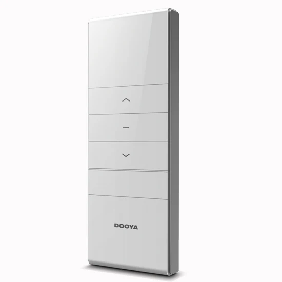
My remote is dooya. And sniff code:
10000011 01000010 01001001 11100001 00110011 pause
10000011 01000010 01001001 11100001 01010101 up
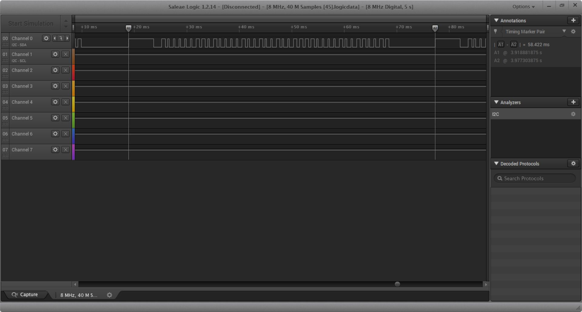
10000011 01000010 01001001 11100001 00111100 downI had use USB Saleae Analyzer sniff code.
But not work, :(
-
Please help me,
My remote is dooya. And sniff code:
10000011 01000010 01001001 11100001 00110011 pause
10000011 01000010 01001001 11100001 01010101 up
10000011 01000010 01001001 11100001 00111100 downI had use USB Saleae Analyzer sniff code.
But not work, :(
-
Please help me,
My remote is dooya. And sniff code:
10000011 01000010 01001001 11100001 00110011 pause
10000011 01000010 01001001 11100001 01010101 up
10000011 01000010 01001001 11100001 00111100 downI had use USB Saleae Analyzer sniff code.
But not work, :(
@かいと The pattern for the control may have changed...? Because you have a recording of the remote I would try to record what you are sending with your transmitter and compare the waveform of the two devices. They should be identical. That is how I ended up figuring out the exact timing needed for my motors.
-
Hi guys,
I realise that this is quite an old thread, but i found it a useful source of info when looking for a solution for my 433MHz problem, so I thought I'd share some of my findings...We have a holiday home in Spain and it has some external 'awnings' that extend over the windows to provide shade from the sun. In Spain these are called Toldos. They operate using tubular motors controlled using 433MHz remote controls – one remote for each awning, three in total. I'd tried all the regular methods to sniff the 433MHz protocol, but none of the standard Arduino libraries would even acknowledge that the remote was sending out any sort of signal. Other remotes, such as garage door openers, PIR detectors etc work fine with my sniffer, so the hardware/software I was using is good.
I eventually resorted to using my sound card and Audacity software to capture the transmissions from the remote controls and this work surprisingly well (I'd tried every digital approach you can imagine up to this point, including a logic analyser, and was reluctant to try the analogue approach but wish I’d trued it earlier).
What I discovered is that when I press either the UP or the Down buttons on the remote, it transmits a timing pulse followed by 40 bits of data. At first I thought that this sequence was repeated 8 times, but I eventually realised that one 40-bit code was used for the first 4 repetitions of the data, followed by a different code for the next 4 repetitions. I later realised that whenever one of these buttons is pressed, the initial 40 bit code is transmitted continuously then the other code is transmitted 4 times when the button is released. When the button is pressed quickly I just get the 'Pressed' code 4 times followed by the 'Released' code 4 times.
The Stop button works slightly differently - only one code is used and this is transmitted at least 4 times and will continue to be transmitted as long as the button is pressed. (in other words, the Stop button has a 'Pressed' code, but not a 'Released' code).It's actually the 'Pressed' code for each button that controls the awnings. The 'Released' code doesn't seem to serve any function with my awnings.
These 'Released' codes really confused me to begin with, as I when I checked two different bursts of data from the same button using Audacity, I was getting different results. This was obviously because on one occasion I’d picked one of the ‘Pressed’ codes to analyse, but on the second occasion I’d inadvertently analysed a ‘Released’ code. At first I’d thought the analogue capture process was unreliable, but then I thought that maybe some sort of rolling code system was being used. I eventually realised what was going on, but not until I'd spent quite a bit of time cursing the remote control and the PC.
I was able to replicate the transmitted code fairly accuracy using a version of @peashooter's code (thanks!) and this worked well
I’m repeating the ‘Pressed’ code 4 times and it seems to work very reliably.As well as being able to control the awnings using an Arduino/ESP8266 transmitter, I also wanted to be able to use the existing handheld remotes, so to be able to understand the current position of each awning I needed a way of receiving the commands from the remotes and using them to keep track of each individual awning. This bought me back to the original problem of not being able to find a way to listen to the 433MHz messages from the remotes using any of the current Arduino libraries.
In started delving into the idea of modifying the RC-Switch library, now that I knew the timing characteristics of the signals. At that point I stumbled across this small library:
https://github.com/bjwelker/Raspi-RolloIt has an Arduino sketch that is written to identify the codes that are being transmitted by remote controllers for blinds, so that these codes can then be used to control the blinds using a Raspberry Pi.
When I ran the Arduino sketch it immediately produced results from my Awning remotes – If only I’d found this earlier!
The results it gives are in a “Quad Bit” format, but when I modified the code to print out the raw received codes they were identical to the results I’d obtained from Audacity.
I’m not interested in using a Pi to transmit the codes to the blinds, and this wasn’t needed anyway, as using @peashooter's code I already had a transmission solution. I’m now in the process of fine-tuning the code that tracks each blind’s position based on the commands that are sent from either the hand-held remotes or my transmitter. The position is simply based on time between the start and stop transmissions and the known time that it takes to fully extend each awning.The primary reason for wanting to control the awnings is that when it gets windy, I want to be able to automatically retract them. I’m using data from a weather station to monitor the wind speed and if it meets the criteria (very strong winds for a short period, or not quite so strong winds for a slightly longer period, then the awnings will be retracted (assuming that they’re extended of course). I’m also automatically retracting them when it gets dark, as it’s easy to forget to do this and a bit cumbersome to walk around and do all three awnings using the separate hand-held remote controls.
Here’s some pictures of one of the remotes:
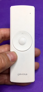
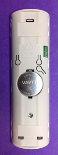

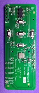
The brand name on the remote is Gaviota and the circuit board says “Designed by D Team” “DC104/105” “V2.1” and “No.DA288”.
Here are what the awnings look like:
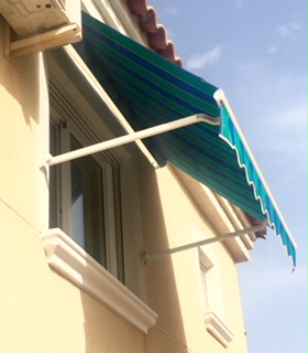
I have no idea what the brand name is on the tubular motors, as they’re hidden inside the mechanism.
Hopefully this saves someone at least some of the pain that I’ve been through to get to this point.Pete.
-
I recently figured out how to control my Blinds.com motorized cellular shades (http://www.blinds.com/control/product/productID,97658) with my Vera 3. The blinds have Dooya DV24CE motors (which use a 433 MHz RF for remote control) built into them but I couldn't find any already built RF transmitter that integrated directly with the Vera. I had recently started building Arduino sensors with Henrik's amazing MySensors Arduino Sensor Plugin (http://www.mysensors.org) so I decided to try to build my own. Thanks to many helpful resources on the internet I was able to control my blinds for less than $20 in Arduino parts.
Here is a link to a YouTube video with an overview of the process: http://youtu.be/EorIqw-9eJw
Here is a pdf with more info on the process if you are interested in doing it yourself:
Controlling Blinds.com RF Dooya Motors with Arduino and Vera.pdfArduino Code MySensors Version 2.x:
https://gist.github.com/petewill/ac31b186291743e046f83497de0ffa87And the Arduino Code (OLD CODE):
BlindsVera.ino2020-12-06: Edited to add updated code
@petewill
Great guide.
I stumbled upon this when I realised that my Debel awning was using a Dooya motor and remote.I did not use your cool system with the soundcard to sniff the RF codes, but instead used my RTL-SDR usb receiver, since I already had it laying around 😀
After finding the codes I programmed an Arduino with it and connected it to my OpenHAB installation. Now the awning can be controlled with the OpenHAB app, and my wife just loves it 😀
Just wanted to point it out for others looking for RF codes for Debel awnings.
-
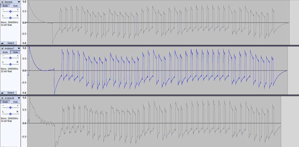
I recognize this is an old post, but I've not found any newer discussion and I have hit a roadblock. I've followed all of the very helpful posts to build a sniffer and decode it as tools like RCSwitch wouldn't work. I even used @PeteKnight 's tip to notice there was a different code sent initially when a button was pressed. I've tried sending both versions, emulating the initial (timing?) signal at the start. I tweaked the high and low delays and I think I've got a rf signal that is extremely close to the one from the remote. Here are the two different sources in audacity for comparison.
//Define Variables
#define GND 3
#define VCC 4
#define DATA 5 //Data pin for RF Transmitter
#define ZERO_HIGH 307 //Delay for the high part of a 0 in microseconds
#define ZERO_LOW 750 //Delay for the low part of a 0 in microseconds
#define ONE_HIGH 648 //Delay for the high part of a 1 in microseconds
#define ONE_LOW 409 //Delay for the low part of a 1 in microseconds

int startUp = 1;

unsigned char standardBits1 = 0b00001111; //integer value of the 28 bit standard sequence referenced above. "0b" prefix is for *******
unsigned char standardBits2 = 0b01111100;
unsigned char standardBits3 = 0b01100100;
unsigned char standardBits4 = 0b00000001;
unsigned char standardBits5 = 0b00011110;


void setup() {
  pinMode(GND,OUTPUT);
  pinMode(VCC,OUTPUT);
  pinMode(DATA,INPUT);
  digitalWrite(GND,LOW);
  digitalWrite(VCC,HIGH);

   Serial.begin(9600);

}

void loop() {
 unsigned char i;
      delay(3000);
    if(startUp ==1){
    for(i=0;i<10;i++) {
      delay(1000);
      digitalWrite(DATA, HIGH);
      delayMicroseconds(5000);
      digitalWrite(DATA, LOW);
      delayMicroseconds(1500);

      eightBits(standardBits1);
      eightBits(standardBits2);
      eightBits(standardBits3);
      eightBits(standardBits4);
      eightBits(standardBits5);
      startUp = 0;
    }
 }
}
      void eightBits(unsigned char bits){

          unsigned char k;
          int delayTime;
          for(k=0;k<8;k++) {
            int highTime;
            int lowTime;
            delayTime = ((bits>>(7-k)) & 1 ? 1 : 0);

            if (delayTime == 1){
              highTime = ONE_HIGH;
              lowTime = ONE_LOW;
            }
            else {
              highTime = ZERO_HIGH;
              lowTime = ZERO_LOW;
            }
              digitalWrite(DATA, HIGH);
              delayMicroseconds(highTime);
              digitalWrite(DATA, LOW);
              delayMicroseconds(lowTime);
        }

}
Here are all the codes I was able to extract from audacity for one of the blinds.
Down1: 00001111 01111100 01100100 00000001 00111100
Up1: 00001111 01111100 01100100 00000001 00011110
Stop1: 00001111 01111100 01100100 00000001 01010101
Start1: 00001111 01111100 01100100 00000001 00010001
Does anyone have an idea of what I might still be missing in getting this work? -
I recognize this is an old post, but I've not found any newer discussion and I have hit a roadblock. I've followed all of the very helpful posts to build a sniffer and decode it as tools like RCSwitch wouldn't work. I even used @PeteKnight 's tip to notice there was a different code sent initially when a button was pressed. I've tried sending both versions, emulating the initial (timing?) signal at the start. I tweaked the high and low delays and I think I've got a rf signal that is extremely close to the one from the remote. Here are the two different sources in audacity for comparison.
//Define Variables
#define GND 3
#define VCC 4
#define DATA 5 //Data pin for RF Transmitter
#define ZERO_HIGH 307 //Delay for the high part of a 0 in microseconds
#define ZERO_LOW 750 //Delay for the low part of a 0 in microseconds
#define ONE_HIGH 648 //Delay for the high part of a 1 in microseconds
#define ONE_LOW 409 //Delay for the low part of a 1 in microseconds

int startUp = 1;

unsigned char standardBits1 = 0b00001111; //integer value of the 28 bit standard sequence referenced above. "0b" prefix is for *******
unsigned char standardBits2 = 0b01111100;
unsigned char standardBits3 = 0b01100100;
unsigned char standardBits4 = 0b00000001;
unsigned char standardBits5 = 0b00011110;


void setup() {
  pinMode(GND,OUTPUT);
  pinMode(VCC,OUTPUT);
  pinMode(DATA,INPUT);
  digitalWrite(GND,LOW);
  digitalWrite(VCC,HIGH);

   Serial.begin(9600);

}

void loop() {
 unsigned char i;
      delay(3000);
    if(startUp ==1){
    for(i=0;i<10;i++) {
      delay(1000);
      digitalWrite(DATA, HIGH);
      delayMicroseconds(5000);
      digitalWrite(DATA, LOW);
      delayMicroseconds(1500);

      eightBits(standardBits1);
      eightBits(standardBits2);
      eightBits(standardBits3);
      eightBits(standardBits4);
      eightBits(standardBits5);
      startUp = 0;
    }
 }
}
      void eightBits(unsigned char bits){

          unsigned char k;
          int delayTime;
          for(k=0;k<8;k++) {
            int highTime;
            int lowTime;
            delayTime = ((bits>>(7-k)) & 1 ? 1 : 0);

            if (delayTime == 1){
              highTime = ONE_HIGH;
              lowTime = ONE_LOW;
            }
            else {
              highTime = ZERO_HIGH;
              lowTime = ZERO_LOW;
            }
              digitalWrite(DATA, HIGH);
              delayMicroseconds(highTime);
              digitalWrite(DATA, LOW);
              delayMicroseconds(lowTime);
        }

}
Here are all the codes I was able to extract from audacity for one of the blinds.
Down1: 00001111 01111100 01100100 00000001 00111100
Up1: 00001111 01111100 01100100 00000001 00011110
Stop1: 00001111 01111100 01100100 00000001 01010101
Start1: 00001111 01111100 01100100 00000001 00010001
Does anyone have an idea of what I might still be missing in getting this work?@ssuckow I can't see the image but when I did this I started in small steps. Your first goal is to send a successful signal without all the MySensors code. I just created a standalone program with all my code in the setup so when it ran it would send a raise, stop or lower signal. Once you do that you can integrate it with MySensors much easier. It sounds like you have mostly done this based on your description above but I'm not sure. Also, are you sure the hardware is wired correctly? Is the 433Mhz device is getting enough power to send the signal to the blinds?
-
I recognize this is an old post, but I've not found any newer discussion and I have hit a roadblock. I've followed all of the very helpful posts to build a sniffer and decode it as tools like RCSwitch wouldn't work. I even used @PeteKnight 's tip to notice there was a different code sent initially when a button was pressed. I've tried sending both versions, emulating the initial (timing?) signal at the start. I tweaked the high and low delays and I think I've got a rf signal that is extremely close to the one from the remote. Here are the two different sources in audacity for comparison.
//Define Variables
#define GND 3
#define VCC 4
#define DATA 5 //Data pin for RF Transmitter
#define ZERO_HIGH 307 //Delay for the high part of a 0 in microseconds
#define ZERO_LOW 750 //Delay for the low part of a 0 in microseconds
#define ONE_HIGH 648 //Delay for the high part of a 1 in microseconds
#define ONE_LOW 409 //Delay for the low part of a 1 in microseconds

int startUp = 1;

unsigned char standardBits1 = 0b00001111; //integer value of the 28 bit standard sequence referenced above. "0b" prefix is for *******
unsigned char standardBits2 = 0b01111100;
unsigned char standardBits3 = 0b01100100;
unsigned char standardBits4 = 0b00000001;
unsigned char standardBits5 = 0b00011110;


void setup() {
  pinMode(GND,OUTPUT);
  pinMode(VCC,OUTPUT);
  pinMode(DATA,INPUT);
  digitalWrite(GND,LOW);
  digitalWrite(VCC,HIGH);

   Serial.begin(9600);

}

void loop() {
 unsigned char i;
      delay(3000);
    if(startUp ==1){
    for(i=0;i<10;i++) {
      delay(1000);
      digitalWrite(DATA, HIGH);
      delayMicroseconds(5000);
      digitalWrite(DATA, LOW);
      delayMicroseconds(1500);

      eightBits(standardBits1);
      eightBits(standardBits2);
      eightBits(standardBits3);
      eightBits(standardBits4);
      eightBits(standardBits5);
      startUp = 0;
    }
 }
}
      void eightBits(unsigned char bits){

          unsigned char k;
          int delayTime;
          for(k=0;k<8;k++) {
            int highTime;
            int lowTime;
            delayTime = ((bits>>(7-k)) & 1 ? 1 : 0);

            if (delayTime == 1){
              highTime = ONE_HIGH;
              lowTime = ONE_LOW;
            }
            else {
              highTime = ZERO_HIGH;
              lowTime = ZERO_LOW;
            }
              digitalWrite(DATA, HIGH);
              delayMicroseconds(highTime);
              digitalWrite(DATA, LOW);
              delayMicroseconds(lowTime);
        }

}
Here are all the codes I was able to extract from audacity for one of the blinds.
Down1: 00001111 01111100 01100100 00000001 00111100
Up1: 00001111 01111100 01100100 00000001 00011110
Stop1: 00001111 01111100 01100100 00000001 01010101
Start1: 00001111 01111100 01100100 00000001 00010001
Does anyone have an idea of what I might still be missing in getting this work? -
@ssuckow I can't see the image but when I did this I started in small steps. Your first goal is to send a successful signal without all the MySensors code. I just created a standalone program with all my code in the setup so when it ran it would send a raise, stop or lower signal. Once you do that you can integrate it with MySensors much easier. It sounds like you have mostly done this based on your description above but I'm not sure. Also, are you sure the hardware is wired correctly? Is the 433Mhz device is getting enough power to send the signal to the blinds?
-
@ssuckow said in Controlling Blinds.com RF Dooya Motors with Arduino and Vera:
pinMode(DATA,INPUT);Why data pin is input? I think it should be output.
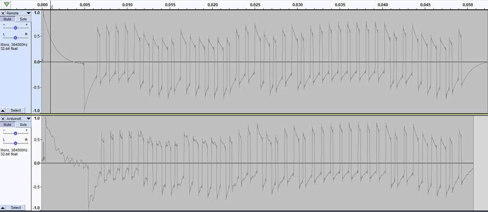
@doteq You are correct. That was a holdover from when I was trying to sniff. I tweaked that and this image shows the updated version as Arduino7. Apparently it worked with it defined as input (as receiver connected to audacity was picking it up), but their was a lot more noise. Now, the signal looks very much like the source remote. However, It still doesn't move the blinds. :disappointed:
-
From the code it looks like you're switching on the receiver by enabling the gnd and vcc pins with an output of the microcontroller. Do you have additional transistors to do so, or just with the output pins directly? In the last case I would recommend to connect it to gnd and vcc directly, to make sure enough current is available.
-
@doteq You are correct. That was a holdover from when I was trying to sniff. I tweaked that and this image shows the updated version as Arduino7. Apparently it worked with it defined as input (as receiver connected to audacity was picking it up), but their was a lot more noise. Now, the signal looks very much like the source remote. However, It still doesn't move the blinds. :disappointed:
@ssuckow what you’ve posted seems to be a good match for the original.
I’m wondering, based on your other comments, if your blinds need the message repeating several times (with my blinds it’s 4 times) or if the initial message is a sort of ‘stand by to receive a command’ instruction that needs to then be followed by the command message (maybe multiple times?).
Try quickly stabbing at the remote control button whilst recording in Audacity and look at the bigger picture. This might give you a bigger picture of the complete command set that the remote is sending when a button is pressed.Pete.
-
@PeteKnight I'm also trying to control my Gaviota awnings with no success, my remote is not from Gaviota but a white label one (It says it uses rolling codes - it's the MX96 https://cloud.motorline.pt/download/manuais/eletronica/mx95-96-97_pt.pdf). I've tried decoding the codes with a cheap RF receiver hooked up with an ESP32 with espHome. I can get some codes sometimes, if I keep my finger pressed for a long time, but none of them work and they do not seam consistent. Since I do not have a raspberry I cannot run that code from Raspi-Rollo.
How did you use audacity to decode the codes? Would you mind sharing the codes you got so I can see if they work here? I have 2 awnings, and I can select which one I control on the remote, does that mean that they are using different codes?
Thanks
@mmartins if you re-read what I wrote, you’ll see that the Raspi-Rollo software has an Arduino sketch to identity the codes. I ran this on a NodeMCU, so it should work on an ESP32.
If you need to use Audacity then the process is well documented in the links earlier in this topic.I have three blinds and they all use independent remotes and each blind has its own codes.
I’m not sure how my codes will help with yours, but here are the codes for one of my blinds:Up
1011101000110000111011101001000100010001Stop
1011101000110000111011101001000101010101Down
1011101000110000111011101001000100110011If your blinds do actually use rolling codes the I don’t think you’ll be able to control them the same way that I do.
Pete.
-
I recently figured out how to control my Blinds.com motorized cellular shades (http://www.blinds.com/control/product/productID,97658) with my Vera 3. The blinds have Dooya DV24CE motors (which use a 433 MHz RF for remote control) built into them but I couldn't find any already built RF transmitter that integrated directly with the Vera. I had recently started building Arduino sensors with Henrik's amazing MySensors Arduino Sensor Plugin (http://www.mysensors.org) so I decided to try to build my own. Thanks to many helpful resources on the internet I was able to control my blinds for less than $20 in Arduino parts.
Here is a link to a YouTube video with an overview of the process: http://youtu.be/EorIqw-9eJw
Here is a pdf with more info on the process if you are interested in doing it yourself:
Controlling Blinds.com RF Dooya Motors with Arduino and Vera.pdfArduino Code MySensors Version 2.x:
https://gist.github.com/petewill/ac31b186291743e046f83497de0ffa87And the Arduino Code (OLD CODE):
BlindsVera.ino2020-12-06: Edited to add updated code
This post is deleted! -
I recently figured out how to control my Blinds.com motorized cellular shades (http://www.blinds.com/control/product/productID,97658) with my Vera 3. The blinds have Dooya DV24CE motors (which use a 433 MHz RF for remote control) built into them but I couldn't find any already built RF transmitter that integrated directly with the Vera. I had recently started building Arduino sensors with Henrik's amazing MySensors Arduino Sensor Plugin (http://www.mysensors.org) so I decided to try to build my own. Thanks to many helpful resources on the internet I was able to control my blinds for less than $20 in Arduino parts.
Here is a link to a YouTube video with an overview of the process: http://youtu.be/EorIqw-9eJw
Here is a pdf with more info on the process if you are interested in doing it yourself:
Controlling Blinds.com RF Dooya Motors with Arduino and Vera.pdfArduino Code MySensors Version 2.x:
https://gist.github.com/petewill/ac31b186291743e046f83497de0ffa87And the Arduino Code (OLD CODE):
BlindsVera.ino2020-12-06: Edited to add updated code
This post is deleted!