HC-SR501 on batteries
-
@dbemowsk You asked a question and I got you the answer. It took me less than 5 minutes to find out which chipdoes that breakboard use, and find the two datasheets in google.
Thanks for explaning to me the reason for the different voltage specs, but that was not necessary.
You're welcome by the way.
@manutremo I didn't mean to sound like I didn't appreciate the help. Sorry if I came off that way. I was merely making light of the fact that I mentioned removing the diode and regulator in my OP. Thanks for the help.
-
@Yveaux So basically you are running it with 5 batteries? I was hoping to keep it down to 2xAA batteries if possible. I know some have said that the noise from some buck-boost converters can really affect the accuracy, are there any good ones that would work reasonably well for something like this? I see many go down to as low as 1.8v to boost to 3.3v.
@dbemowsk said in HC-SR501 on batteries:
@Yveaux So basically you are running it with 5 batteries?
No, just 3. See my sketches in this thread: https://forum.mysensors.org/topic/6511/hc-sr501-3-3v-randomly-sends-tripped-when-radio-is-on/22
This way you won't need a converter at all.
-
@dbemowsk said in HC-SR501 on batteries:
@Yveaux So basically you are running it with 5 batteries?
No, just 3. See my sketches in this thread: https://forum.mysensors.org/topic/6511/hc-sr501-3-3v-randomly-sends-tripped-when-radio-is-on/22
This way you won't need a converter at all.
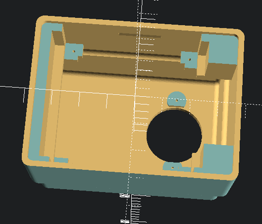
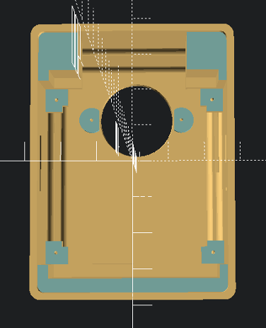
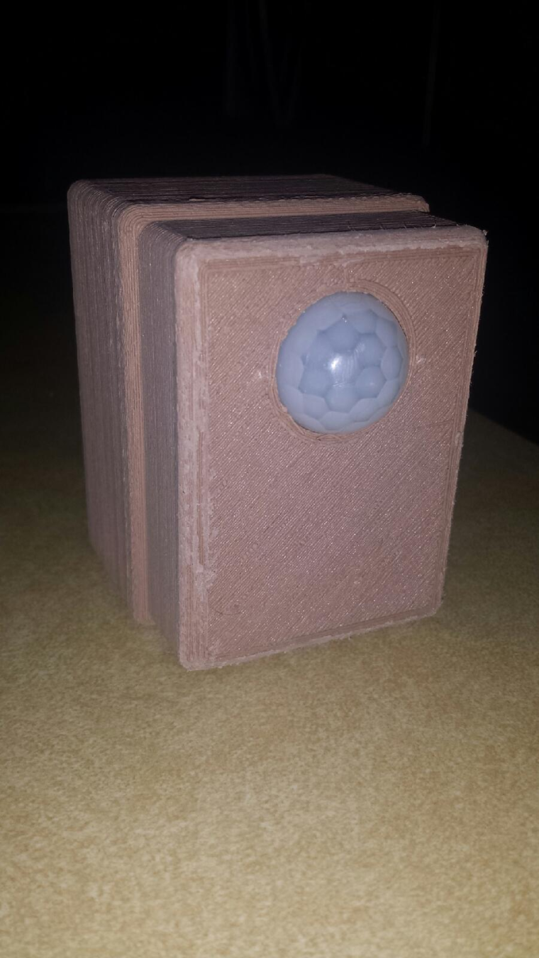
@Yveaux I like that idea. The wall mount enclosure that I am planning on testing things with is an offshoot of my temp/humidity sensor enclosure. Here are some of the cad pics that I did in OpenSCAD.
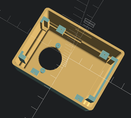
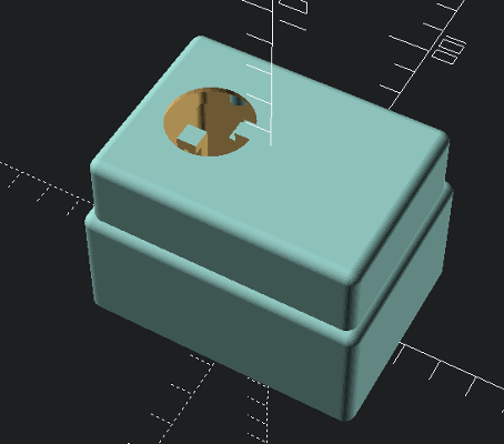
This has the supports for holding a 2xAA battery case. I do not have any 3xAA battery cases, but I could get some and modify the design to fit it. I completely overhauled the OpenSCAD design for the temp/humidity sensor last week, so making slight changes in the case design should be fairly easy. For anyone interested, here is the OpenSCAD code for the drawings you see.//Humidity sensor project box // //Created by: Dan Bemowski //Email : dbemowsk[at]phpwebscripting.com //Website : https://dan.bemowski.info // //This is version 3 of my humidity sensor project box. Though originally designed as a wall mount //box for a temperature and humidity sensor, this can be used for any number of things. This new //version of the box also has nice rounded corners unlike the square corners of the previous version. //This OpenSCAD file is highly configurable. By changing a few variables you can change the size of //the box while not changing the PCB mounting tabs or the slots for holding the battery case. // //Some parts of the box are optional and can be turned on or off by setting their draw variables to //true or false. // // draw_vent_holes - allows you to optionally include the vented holes in the top of the box // draw_wire_slots - This in conjunction with a couple other variables lets you create a box // cover that has slots to allow wires to exit the box. The wire slots // currently can only be put on the 2 short sides which is where the battery // case holder is, so the battery case cannot be used if wire slots are added. // draw_battery_case - Allows you to add a slot for holding a battery case. Currently the only // battery case used for the project is a 2 x AA battery case, but with a few // changes can be made to fit other types of battery cases/holders. $fn = 36; //A simple fudge factor for previewing fudge = 0.01; //This variable tells which parts of the box are rendered. Options - cover, wall_plate, all render_parts = "cover"; //These variables are for creating the main box //------------------------------------------------------------------------------------------------- //This is the height of the vented top part of the box vent_top_h = 20; inner_vent_lip = 5; vent_edge_start = 1; vent_holes_x = 14; vent_holes_y = 10; main_box_x = 77; main_box_y = 57; main_box_h = 35; box_wall_t = 2; box_top_t = 4; vented_top_x = main_box_x-(box_wall_t*2); vented_top_y = main_box_y-(box_wall_t*2); radio_relief_x = 35; radio_relief_y = 2; radio_relief_h = 10; rounded_edge_r = 3; inner_rounded_edge_r = rounded_edge_r-(box_wall_t/2); //Tell whether or not to include the vents in the top of the box draw_vent_holes = false; //------------------------------------------------------------------------------------------------- //These variables are for creating the wall plate //------------------------------------------------------------------------------------------------- wall_plate_lip_play = 0.25; //This is to give the wall plate a tiny bit of recess for the edge to //fit inside the bottom of the box to allow it to sit on the lip wall_plate_base_x = main_box_x-(box_wall_t*2)-(wall_plate_lip_play*2); wall_plate_base_y = main_box_y-(box_wall_t*2)-(wall_plate_lip_play*2); wall_plate_base_t = 2; //How thick the main bottom plate should be not including the lip thickness wall_plate_base_lip_w = box_wall_t+wall_plate_lip_play; wall_plate_base_lip_t = 1; //Thickness of the bottom lip wall_plate_snap_upright_w = 16; wall_plate_snap_upright_h = 10; wall_plate_snap_upright_t = 3; wall_plate_snap_latch_w = 2; //Since we are rotating the snap latch 45 degrees, we need to figure out the corner //to corner length (hypotenuse) of 1/2 of the rotated latch wall_plate_snap_latch_center = sqrt(pow(2,wall_plate_snap_latch_w)+pow(2,wall_plate_snap_latch_w)); mount_screw_hole_d = 4; mount_screw_head_d = 8; mount_screw_x_edge_dist = 15; //------------------------------------------------------------------------------------------------- //These variables are for creating the wire slots if used //------------------------------------------------------------------------------------------------- wire_hole_d = 2.75; num_slots_left = 2; num_slots_right = 3; draw_wire_slots = false; //------------------------------------------------------------------------------------------------- //These variables are for creating the battery case. The battery case //that I used initially holds 2-AA batteries and has a power switch (sw). //This is the view with the power switch facing down (bottom side) // ------------------------------- // | s | |\ // | w | battery 1 | \ ____X // | |__________________________ | | |\ // | | | | | \ //wires ---| | battery 2 | | Y Z // ---| | | | // \-------------------------------\ | // \ \ | // \_______________________________\| //------------------------------------------------------------------------------------------------- //Battery case size batt_case_x = 68.75; batt_case_y = 34; batt_case_t = 18.4; //Battery case edge play. Adjust this if the battery case fits too loose or tight in the box batt_case_edge_play = 0.5; //How far the power wires are from the edge edge_y_to_wires = 6; //This is the minimum edge depth for the battery case holder batt_holder_min_edge_d = 6; //Battery holder lip width batt_holder_lip_w = 3; //this is the amount of space needed for the wires to bend out of the edge of the battery box to //go into the main box for connection to the circuit board. min_wire_relief = 2; //Here we are going to do a test calculation to figure out if the defined battery case size can //fit within the boundaries of the outer box. We'll show an error if the case won't fit if (batt_case_x > (main_box_x-(box_wall_t*2)-min_wire_relief)) { echo ("-------------------------------------------------------------------"); echo ("| ERROR: The battery case X dimention is to long for the box size |"); echo ("-------------------------------------------------------------------"); } //Tell whether or not we want to include the battery case holder in the final render of the box draw_battery_case = true; //If we are adding wire slots, we cannot draw the battery case, regardless of the variable above battery_case = (draw_wire_slots) ? false : draw_battery_case; //------------------------------------------------------------------------------------------------- //These variables are for creating the PCB mounting tabs //------------------------------------------------------------------------------------------------- pcb_x = 48.75; pcb_y = 50; pcb_mount_holes_x = 45.6; pcb_mount_holes_y = 46.6; pcb_mount_hole_x_to_tab_edge = 3.5; pcb_screw_hole_d = 1; pcb_inner_edge_to_mount_hole = 1.75; pcb_outer_edge_to_mount_hole = 2; box_edge_x_to_mount_tab = 15; pcb_mount_tab_h = 23; //Where the mount tabs start from the bottom of the box pcb_mount_tab_t = 3; //Mounting tab thickness pcb_mount_tab_w = 7; //Mounting tab width //------------------------------------------------------------------------------------------------- //These variables are for creating the motion sensor mounting posts //------------------------------------------------------------------------------------------------- ms_eye_d = 23; ms_mounting_screw_w = 29; ms_screw_post_h = 3.5; ms_screw_post_d = 5; ms_screw_hole_d = 1; ms_board_l = 32.7; ms_board_w = 24; //------------------------------------------------------------------------------------------------- module wall_plate() { //Create the base platform with mounting holes difference() { union() { translate([0, 0, -wall_plate_base_lip_t]) cube([wall_plate_base_x+(wall_plate_base_lip_w*2), wall_plate_base_y+(wall_plate_base_lip_w*2), wall_plate_base_lip_t]); minkowski() { translate([inner_rounded_edge_r+wall_plate_base_lip_w, inner_rounded_edge_r+wall_plate_base_lip_w, 0]) cube([wall_plate_base_x-(inner_rounded_edge_r*2), wall_plate_base_y-(inner_rounded_edge_r*2), wall_plate_base_t]); cylinder(1/rounded_edge_r, inner_rounded_edge_r); } } translate([mount_screw_x_edge_dist, (wall_plate_base_y+(wall_plate_base_lip_w*2))/2, -wall_plate_base_lip_t-fudge]) cylinder(wall_plate_base_t+(fudge*2),d=mount_screw_hole_d); translate([(wall_plate_base_x+(wall_plate_base_lip_w*2))-mount_screw_x_edge_dist, (wall_plate_base_y+(wall_plate_base_lip_w*2))/2, -wall_plate_base_lip_t-fudge]) cylinder(wall_plate_base_t+(fudge*2), d=mount_screw_hole_d); translate([mount_screw_x_edge_dist, (wall_plate_base_y+(wall_plate_base_lip_w*2))/2, wall_plate_base_lip_t]) cylinder(wall_plate_base_t, d=mount_screw_head_d); translate([(wall_plate_base_x+(wall_plate_base_lip_w*2))-mount_screw_x_edge_dist, (wall_plate_base_y+(wall_plate_base_lip_w*2))/2, wall_plate_base_lip_t]) cylinder(wall_plate_base_t, d=mount_screw_head_d); } //Create the snap tab uprights difference() { translate([((wall_plate_base_x+(wall_plate_base_lip_w*2))/2)-(wall_plate_snap_upright_w/2), wall_plate_base_lip_w, 0]) cube([wall_plate_snap_upright_w, wall_plate_base_y, wall_plate_snap_upright_h]); translate([((wall_plate_base_x+(wall_plate_base_lip_w*2))/2)-(wall_plate_snap_upright_w/2)-fudge, wall_plate_base_lip_w+wall_plate_snap_upright_t, 0]) cube([wall_plate_snap_upright_w+(fudge*2), wall_plate_base_y-(wall_plate_snap_upright_t*2), wall_plate_snap_upright_h+fudge]); } //Create the latches latches(); } module latches() { //Create the latches translate([((wall_plate_base_x+(wall_plate_base_lip_w*2))/2)-(wall_plate_snap_upright_w/2)-fudge, wall_plate_base_lip_w, wall_plate_snap_upright_h-wall_plate_snap_latch_center]) rotate([45, 0, 0]) cube([wall_plate_snap_upright_w, wall_plate_snap_latch_w, wall_plate_snap_latch_w]); translate([((wall_plate_base_x+(wall_plate_base_lip_w*2))/2)-(wall_plate_snap_upright_w/2)-fudge, wall_plate_base_y+wall_plate_base_lip_w, wall_plate_snap_upright_h-wall_plate_snap_latch_center]) rotate([45, 0, 0]) cube([wall_plate_snap_upright_w, wall_plate_snap_latch_w, wall_plate_snap_latch_w]); } module cover() { //Create the main vented box difference() { //Create the outer box layers union() { minkowski() { translate([rounded_edge_r+box_wall_t, rounded_edge_r+box_wall_t, 0]) cube([vented_top_x-(rounded_edge_r*2), vented_top_y-(rounded_edge_r*2), main_box_h+vent_top_h-rounded_edge_r]); sphere(rounded_edge_r); } minkowski() { translate([rounded_edge_r, rounded_edge_r, 0]) cube([main_box_x-(rounded_edge_r*2), main_box_y-(rounded_edge_r*2), main_box_h-rounded_edge_r]); sphere(rounded_edge_r); } } //Cut off the bottom rounded edge translate([0, 0, -rounded_edge_r-fudge]) cube([main_box_x+fudge, main_box_y+fudge, rounded_edge_r+fudge]); //Hollow out the box inner_rounded_edge_r minkowski() { translate([inner_rounded_edge_r+box_wall_t*2, inner_rounded_edge_r+box_wall_t*2, -fudge]) cube([vented_top_x-(box_wall_t*2)-(inner_rounded_edge_r*2), vented_top_y-(box_wall_t*2)-(inner_rounded_edge_r*2), main_box_h+vent_top_h-box_top_t]); sphere(inner_rounded_edge_r); } minkowski() { translate([inner_rounded_edge_r+box_wall_t, inner_rounded_edge_r+box_wall_t, -fudge]) cube([main_box_x-(box_wall_t*2)-(inner_rounded_edge_r*2), main_box_y-(box_wall_t*2)-(inner_rounded_edge_r*2), main_box_h-inner_vent_lip-box_wall_t+(fudge*2)]); sphere(inner_rounded_edge_r); } //Create the hole for the motion sensor eye translate([(main_box_x/2)-((ms_board_w/2)+inner_vent_lip), (main_box_y/2), main_box_h+vent_top_h-box_top_t]) { cylinder(box_top_t+fudge, d1= ms_eye_d+2, d2=ms_eye_d); } //Create the latch reliefs latches(); //Add some reliefs for wires if (draw_wire_slots) { //Calculate the left slots for(i=[1:num_slots_left]) { y=i*(main_box_y/(num_slots_left+1)); translate([-fudge, y, wall_plate_base_t+(wire_hole_d/2)]) rotate([0, 90, 0]) cylinder(box_wall_t+(fudge*2), d=wire_hole_d); translate([(box_wall_t/2), y, 0]) cube([box_wall_t+(fudge*2), wire_hole_d, wall_plate_base_t+inner_rounded_edge_r+wire_hole_d], center=true); } //Calculate the right slots for(i=[1:num_slots_right]) { y=i*(main_box_y/(num_slots_right+1)); translate([wall_plate_base_x+wall_plate_base_lip_w+0.24, y, wall_plate_base_t+(wire_hole_d/2)]) rotate([0, 90, 0]) cylinder(box_wall_t+(fudge*2), d=wire_hole_d); translate([(box_wall_t/2)+wall_plate_base_x+wall_plate_base_lip_w+0.25, y, 0]) cube([box_wall_t+(fudge*2), wire_hole_d, wall_plate_base_t+inner_rounded_edge_r+wire_hole_d], center=true); } } if (draw_vent_holes) { //Add the horizontal vent slots to the top layer echo (vented_top_x-(box_wall_t+vent_edge_start)); for ( x = [(box_wall_t*2)+vent_edge_start : (vented_top_x-(box_wall_t+vent_edge_start))/vent_holes_x : vented_top_x-(box_wall_t+vent_edge_start)] ){ translate([x, box_wall_t-fudge, main_box_h-rounded_edge_r-inner_vent_lip]) cube([box_wall_t, vented_top_y+(fudge*2), vent_top_h+inner_vent_lip+box_wall_t-(rounded_edge_r+(rounded_edge_r/2))]); } //Add the vertical vent slots to the top layer for ( y = [(box_wall_t*2)+vent_edge_start : (vented_top_y-(box_wall_t+vent_edge_start))/vent_holes_y : vented_top_y-(box_wall_t+vent_edge_start)] ){ translate([box_wall_t-fudge, y, main_box_h-rounded_edge_r-inner_vent_lip]) cube([vented_top_x+(fudge*2), box_wall_t, vent_top_h+inner_vent_lip+box_wall_t-(rounded_edge_r+(rounded_edge_r/2))]); } } //This is a slight relief in the side vents where the radio module sits //to prevent the radio from restin on the side of the vents. This makes //screwing the PCB on easier. translate([(box_wall_t*2)+vent_edge_start, box_wall_t+(box_wall_t/2), 26]) cube([radio_relief_x, radio_relief_y, radio_relief_h]); } //Create the mounting posts for the motion sensor PCB for(i=[0,1]) { translate([(main_box_x/2)-((ms_board_w/2)+inner_vent_lip), (main_box_y/2)-(ms_mounting_screw_w/2)+(ms_mounting_screw_w*i), main_box_h+vent_top_h-box_wall_t-ms_screw_post_h+(fudge*5)]) { difference() { cylinder(ms_screw_post_h, d=ms_screw_post_d); cylinder(ms_screw_post_h, d=ms_screw_hole_d); } } } //Create the battery case holder if (battery_case) { difference() { //This should be a cube the full length of the case with the width and height -- batt_holder_lip_w //determined by the battery case size translate([box_wall_t, (main_box_y/2)-((batt_case_y+(batt_case_edge_play*2)+(batt_holder_lip_w*2))/2), wall_plate_base_t]) cube([main_box_x-(box_wall_t*2), batt_case_y+(batt_case_edge_play*2)+(batt_holder_lip_w*2), batt_case_t+batt_case_edge_play+batt_holder_lip_w]); //This hollows out a space in the middle to be able to fit the circuit board in on it's tabs translate([box_wall_t+batt_holder_min_edge_d, (main_box_y/2)-((batt_case_y+(batt_case_edge_play*2)+(batt_holder_lip_w*2))/2)-(fudge/2), wall_plate_base_t-(fudge/2)]) cube([main_box_x-(box_wall_t*2)-(batt_holder_min_edge_d*2), batt_case_y+(batt_case_edge_play*2)+(batt_holder_lip_w*2)+fudge, batt_case_t+batt_case_edge_play+batt_holder_lip_w+fudge]); //This cuts out the slot for the battery case translate([box_wall_t+min_wire_relief, (main_box_y/2)-((batt_case_y+(batt_case_edge_play*2))/2), wall_plate_base_t-(fudge/2)]) cube([batt_case_x+batt_case_edge_play, batt_case_y+batt_case_edge_play, batt_case_t+batt_case_edge_play]); //Cut out a slot for the power wires edge_y_to_wires translate([box_wall_t, (main_box_y/2)-((batt_case_y+(batt_case_edge_play*2)+(batt_holder_lip_w*2))/2)+edge_y_to_wires, wall_plate_base_t-(fudge/2)]) cube([batt_holder_min_edge_d+fudge, batt_case_y+(batt_case_edge_play*2)+(batt_holder_lip_w*2)-(edge_y_to_wires*2), batt_case_t+batt_case_edge_play+batt_holder_lip_w+fudge]); } } //Create the mounting tabs for the PCB difference() { //Create one large platform to start with union() { translate([box_edge_x_to_mount_tab, box_wall_t, pcb_mount_tab_h]) cube([pcb_mount_holes_x+(pcb_mount_hole_x_to_tab_edge*2), main_box_y-(box_wall_t*2), pcb_mount_tab_t]); translate([box_edge_x_to_mount_tab+2, box_wall_t, pcb_mount_tab_h+pcb_mount_tab_t]) cube([pcb_mount_holes_x+(pcb_mount_hole_x_to_tab_edge*2)-4, main_box_y-(box_wall_t*2), pcb_mount_tab_t]); } //Cut out the center of the platform translate([box_edge_x_to_mount_tab+pcb_mount_hole_x_to_tab_edge+pcb_inner_edge_to_mount_hole, (main_box_y/2)-(pcb_mount_holes_y/2)+pcb_inner_edge_to_mount_hole, (pcb_mount_tab_h)*2-(fudge/2)]) cube([pcb_mount_holes_x-(pcb_inner_edge_to_mount_hole*2), pcb_mount_holes_y-(pcb_inner_edge_to_mount_hole*2), (pcb_mount_tab_t*2)+fudge]); //Now we'll cut out a section to the edge in the Y direction translate([box_edge_x_to_mount_tab+pcb_mount_tab_w, box_wall_t, pcb_mount_tab_h-(fudge/2)]) cube([pcb_mount_holes_x-((pcb_mount_tab_w-pcb_mount_hole_x_to_tab_edge)*2), main_box_y-box_wall_t, (pcb_mount_tab_t*2)+fudge]); //Now cut out the section in the X direction so all that is left is the 4 corner tabs translate([box_edge_x_to_mount_tab-fudge, (main_box_y/2)-(pcb_mount_holes_y/2)+(pcb_mount_tab_w-pcb_mount_hole_x_to_tab_edge), pcb_mount_tab_h-(fudge/2)]) cube([pcb_x+(pcb_mount_hole_x_to_tab_edge*2), pcb_mount_holes_y-((pcb_mount_tab_w-pcb_mount_hole_x_to_tab_edge)*2), (pcb_mount_tab_t*2)+fudge]); //Create the screw holes for(x=[0,1]) { for(y=[0,1]) { translate([box_edge_x_to_mount_tab+pcb_mount_hole_x_to_tab_edge+(x*pcb_mount_holes_x), (main_box_y/2)-(pcb_mount_holes_y/2)+(y*pcb_mount_holes_y), pcb_mount_tab_h-(fudge/2)]) cylinder(pcb_mount_tab_t+fudge, d=pcb_screw_hole_d); } } } } if (render_parts == "all") { translate([-(main_box_x/2), -main_box_y-10, 0]) cover(); translate([-(main_box_x/2), 10, wall_plate_base_lip_t]) wall_plate(); } else if (render_parts == "cover") { translate([-(main_box_x/2), -(main_box_y/2), 0]) cover(); } else if (render_parts == "wall_plate") { translate([-(main_box_x/2), -(main_box_y/2), wall_plate_base_lip_t]) wall_plate(); }For the temp/humidity sensor box, check out my thingiverse page. I have that and other things there.
https://www.thingiverse.com/dbemowsk/designs -
what about using li ion rechargable battery ? it has nominal voltage at 3.7V, max is around 4.2V and drops down to 2.5V ? I have a HC-SR501 module running on 1800mA battery and after more than two months it has 4.08V.
-
what about using li ion rechargable battery ? it has nominal voltage at 3.7V, max is around 4.2V and drops down to 2.5V ? I have a HC-SR501 module running on 1800mA battery and after more than two months it has 4.08V.
@rozpruwacz I am assuming that you are talking about something like an 18650 battery, correct? Are you using an nRF24L01+ radio? If so, the reading I have done on those is that the MAX input voltage on the chip is 3.6v which is below the nominal voltage of the battery. If you are running it at over 4v, I am surprised you haven't burned out the radio. I don't know if the circuit for those radio modules includes a zener diode , but if it does, that may be why you'd be able to run it at a slightly higher voltage.
Vera Plus running UI7 with MySensors, Sonoffs and 1-Wire devices
Visit my website for more Bits, Bytes and Ramblings from me: http://dan.bemowski.info/ -
@rozpruwacz I am assuming that you are talking about something like an 18650 battery, correct? Are you using an nRF24L01+ radio? If so, the reading I have done on those is that the MAX input voltage on the chip is 3.6v which is below the nominal voltage of the battery. If you are running it at over 4v, I am surprised you haven't burned out the radio. I don't know if the circuit for those radio modules includes a zener diode , but if it does, that may be why you'd be able to run it at a slightly higher voltage.
@dbemowsk yes, something like 18650. I'm using nRF24L01 with 3v LDO Voltage Regulator, forgot to mention that.
-
@dbemowsk yes, something like 18650. I'm using nRF24L01 with 3v LDO Voltage Regulator, forgot to mention that.
@rozpruwacz Which regulator if I might ask?
-
APE8865Y5-30-HF-3
-
I would use XC6206, it's extremely cheap, has a bit lower dropout voltage and more importantly consumes nearly nothing, less than 1/10 of the regulator above.
-
another advantage of using li ion battery is that it is easy to add charging circuit compatible with 5v usb interface or just have separate charger and spare battery.
-
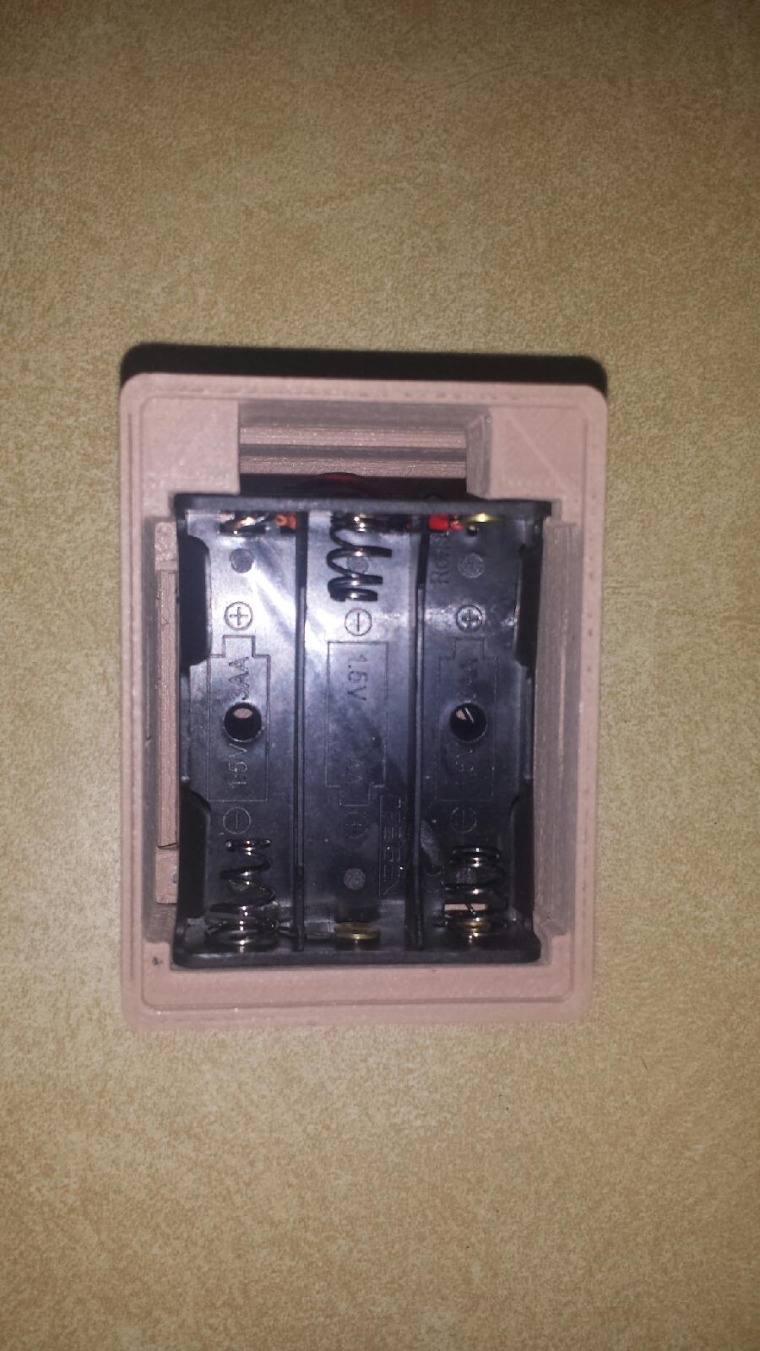
So I had ordered some 3-AAA battery holders and they arrived yesterday. I took one of them and added an orange wire which is my 3v tap, and then the red wire is the 4.5v line. I should have the circuit built today
I am in the process of printing a modified wall box to try this out. I have made the changes needed to fit the new battery holder, just making a few tweaks.
I have posted the new motion sensor box out on thingiverse for anyone interested.
https://www.thingiverse.com/thing:2612414 -
So I had ordered some 3-AAA battery holders and they arrived yesterday. I took one of them and added an orange wire which is my 3v tap, and then the red wire is the 4.5v line. I should have the circuit built today
I am in the process of printing a modified wall box to try this out. I have made the changes needed to fit the new battery holder, just making a few tweaks.
I have posted the new motion sensor box out on thingiverse for anyone interested.
https://www.thingiverse.com/thing:2612414
Hello! It looks like you're interested in this conversation, but you don't have an account yet.
Getting fed up of having to scroll through the same posts each visit? When you register for an account, you'll always come back to exactly where you were before, and choose to be notified of new replies (either via email, or push notification). You'll also be able to save bookmarks and upvote posts to show your appreciation to other community members.
With your input, this post could be even better 💗
Register Login