Skip to content
  • MySensors
  • OpenHardware.io
  • Categories
  • Recent
  • Tags
  • Popular
Skins
  • Light
  • Brite
  • Cerulean
  • Cosmo
  • Flatly
  • Journal
  • Litera
  • Lumen
  • Lux
  • Materia
  • Minty
  • Morph
  • Pulse
  • Sandstone
  • Simplex
  • Sketchy
  • Spacelab
  • United
  • Yeti
  • Zephyr
  • Dark
  • Cyborg
  • Darkly
  • Quartz
  • Slate
  • Solar
  • Superhero
  • Vapor

  • Default (No Skin)
  • No Skin
Collapse
Brand Logo
  1. Home
  2. General Discussion
  3. What did you build today (Pictures) ?

What did you build today (Pictures) ?

Scheduled Pinned Locked Moved General Discussion
1.1k Posts 105 Posters 202.1k Views 98 Watching
  • Oldest to Newest
  • Newest to Oldest
  • Most Votes
Reply
  • Reply as topic
Log in to reply
This topic has been deleted. Only users with topic management privileges can see it.
  • mfalkviddM Offline
    mfalkviddM Offline
    mfalkvidd
    Mod
    wrote on last edited by mfalkvidd
    #26

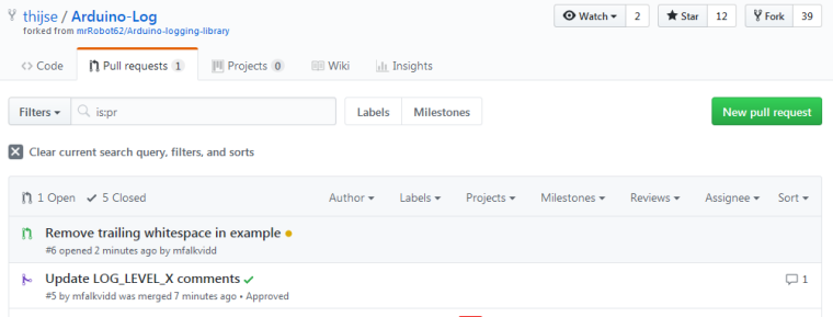
    Not really MySensors-related, but I found a nice logging library for Arduino that I'm using in a project. The library was orphaned some time ago, but now has a new maintainer. I assisted with an update of the documentation and some source code cleanup.
    0_1509023431067_upload-51ff881d-811a-461d-ab1a-7a6189debe28

    1 Reply Last reply
    2
    • NeverDieN Offline
      NeverDieN Offline
      NeverDie
      Hero Member
      wrote on last edited by NeverDie
      #27

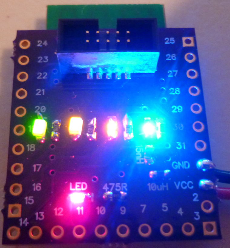
      I made an nRF52832 board today with 5 different colored LED's on it: red, green, yellow, orange, and blue. Mostly I think it may be useful while debugging code. All the LED's except for blue emit light all the way down to 1.8v source voltage, so it's good for battery powered operation also. The blue lights up all the way down to 2.4v, and I had to grapple with a 0403 LED to get that low of a voltage for a blue LED. In the end it was so tiny that I couldn't see the polarity of it, so I hit on the idea of running a blink program and seeing whether it would light up just before I soldered it in place. That worked. :)
      0_1509041337509_5led.jpg

      Also, this board channels its serial output over the 10-pin IDC connector, so I used the tool I posted yesterday to read it. Works great, and now I don't have a six pin FTDI connector cluttering up the PCB. :)

      1 Reply Last reply
      2
      • NeverDieN Offline
        NeverDieN Offline
        NeverDie
        Hero Member
        wrote on last edited by
        #28

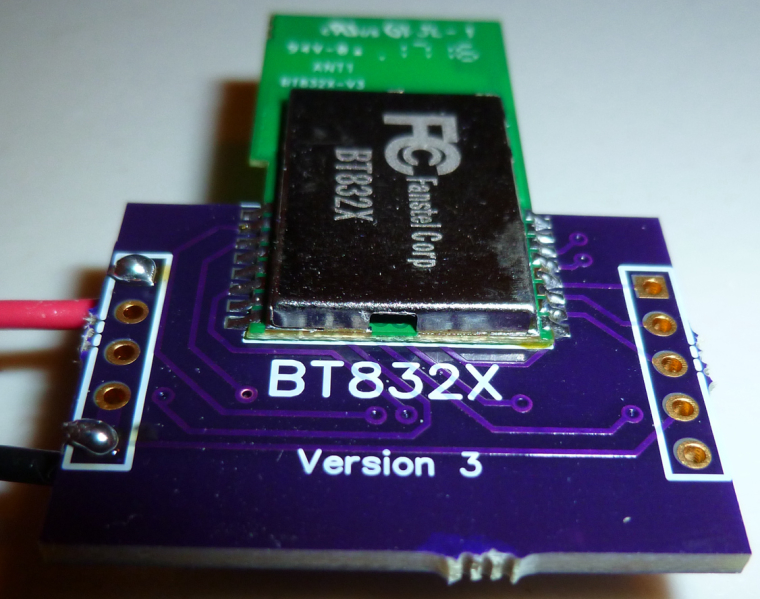
        Today my boards for the BT832X (that's an nRF52832 with both PA and LNA) arrived from OSH PARK, so I put one together to try it out:
        0_1509139587653_BT832X_1.jpg

        1 Reply Last reply
        1
        • S Offline
          S Offline
          sPENKMAN
          wrote on last edited by
          #29

          A (long) time ago I had my own Android app which talked xmlrpc to a Python script, which talked serial with my Arduino which in his turn talked 433 Mhz to our outlets turning lights on and off. All was dandy until Android 4 came along and something stopped working security wise and we were send back into the middle ages.

          Today I successfully got MySensors working enabling me to read temp/hum from a node and letting me send Elro signals into the air over 433Mhz from OpenHAB2. Now I can scale, extend and upgrade my sensors and actuators I can move forward and start improving our home.

          Arduino Uno r3, 433Mhz transmitter, DHT11 sensor

          1 Reply Last reply
          4
          • I Offline
            I Offline
            itbeyond
            wrote on last edited by
            #30

            Today I completed the installation of the first of my 4 channel 240V LED light dimmers. This is installed in the roof and supports 4 buttons to turn on/off/increase/decrease each channel. It uses an AC zero crossing detector circuit and can be configured for leading or trailing edge dimming.
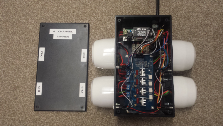
            0_1509325181814_2017-10-06 17.48.30.jpg

            1 Reply Last reply
            6
            • dbemowskD Offline
              dbemowskD Offline
              dbemowsk
              wrote on last edited by
              #31

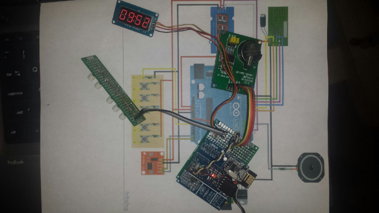
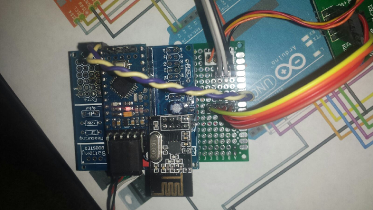
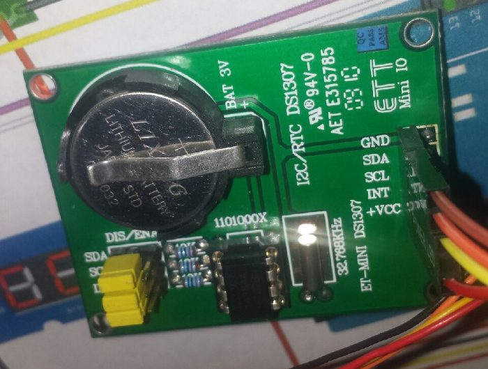
              Working on a smart clock project. Need to make some major code modifications to the example, but should work. I have a test sketch that just passes the time from the RTC to the display, so I know that is all working.

              0_1509332623272_upload-b119edce-2231-4ce0-9b9c-c5bd4ca629d5
              0_1509332689597_upload-2dbe753a-35af-4793-bf46-52669aed4bb0
              0_1509332950856_upload-a1744ea1-3830-4cf6-816b-f273431a596b

              Vera Plus running UI7 with MySensors, Sonoffs and 1-Wire devices
              Visit my website for more Bits, Bytes and Ramblings from me: http://dan.bemowski.info/

              1 Reply Last reply
              3
              • sundberg84S Offline
                sundberg84S Offline
                sundberg84
                Hardware Contributor
                wrote on last edited by
                #32

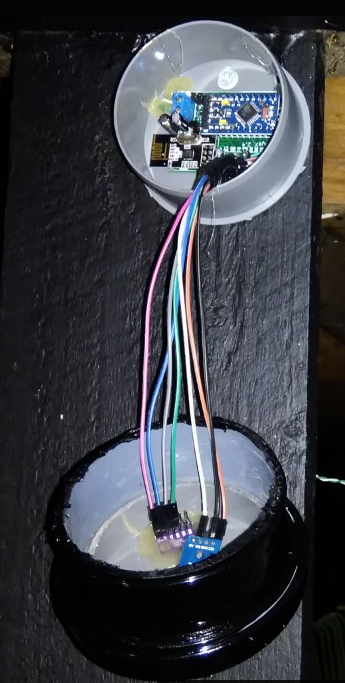
                Last night I made a enclosure to my new outdoor weather station/node. It is made from 2x 70mm sewer pipe end caps and a small sewer pipe to keep them together. Works surprisingly great and looks good.
                Now its painted black and drying - lets hope I can find any daylight this week and mount/deploy it.
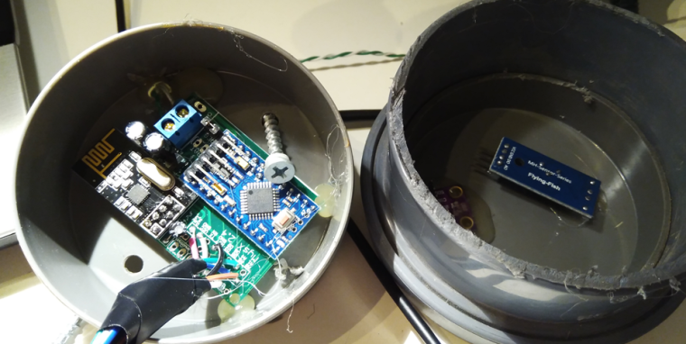
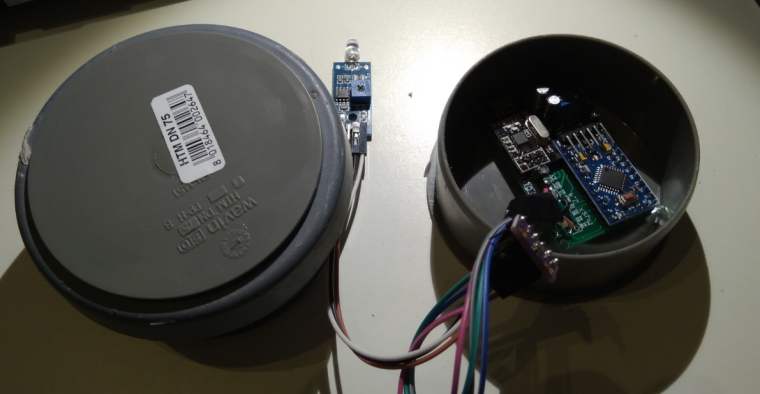
                0_1509350485595_upload-60220e56-06da-42b0-9171-f503ceb23d78
                0_1509350504395_upload-1b94da77-a353-4562-912b-5dd9ba426169

                Controller: Proxmox VM - Home Assistant
                MySensors GW: Arduino Uno - W5100 Ethernet, Gw Shield Nrf24l01+ 2,4Ghz
                MySensors GW: Arduino Uno - Gw Shield RFM69, 433mhz
                RFLink GW - Arduino Mega + RFLink Shield, 433mhz

                dbemowskD 1 Reply Last reply
                3
                • sundberg84S sundberg84

                  Last night I made a enclosure to my new outdoor weather station/node. It is made from 2x 70mm sewer pipe end caps and a small sewer pipe to keep them together. Works surprisingly great and looks good.
                  Now its painted black and drying - lets hope I can find any daylight this week and mount/deploy it.

                  0_1509350485595_upload-60220e56-06da-42b0-9171-f503ceb23d78
                  0_1509350504395_upload-1b94da77-a353-4562-912b-5dd9ba426169

                  dbemowskD Offline
                  dbemowskD Offline
                  dbemowsk
                  wrote on last edited by
                  #33

                  @sundberg84 If this is going to be out in the sun, I would think you'd want it white. Black is going to heat up your electronics quite a bit.

                  Vera Plus running UI7 with MySensors, Sonoffs and 1-Wire devices
                  Visit my website for more Bits, Bytes and Ramblings from me: http://dan.bemowski.info/

                  sundberg84S 1 Reply Last reply
                  0
                  • dbemowskD dbemowsk

                    @sundberg84 If this is going to be out in the sun, I would think you'd want it white. Black is going to heat up your electronics quite a bit.

                    sundberg84S Offline
                    sundberg84S Offline
                    sundberg84
                    Hardware Contributor
                    wrote on last edited by
                    #34

                    @dbemowsk - No worries, no sun! All below a roof so I get shade all the day. The roof is black so I need it to blend in as well.

                    Controller: Proxmox VM - Home Assistant
                    MySensors GW: Arduino Uno - W5100 Ethernet, Gw Shield Nrf24l01+ 2,4Ghz
                    MySensors GW: Arduino Uno - Gw Shield RFM69, 433mhz
                    RFLink GW - Arduino Mega + RFLink Shield, 433mhz

                    1 Reply Last reply
                    1
                    • S Offline
                      S Offline
                      SquareKinematics
                      wrote on last edited by
                      #35

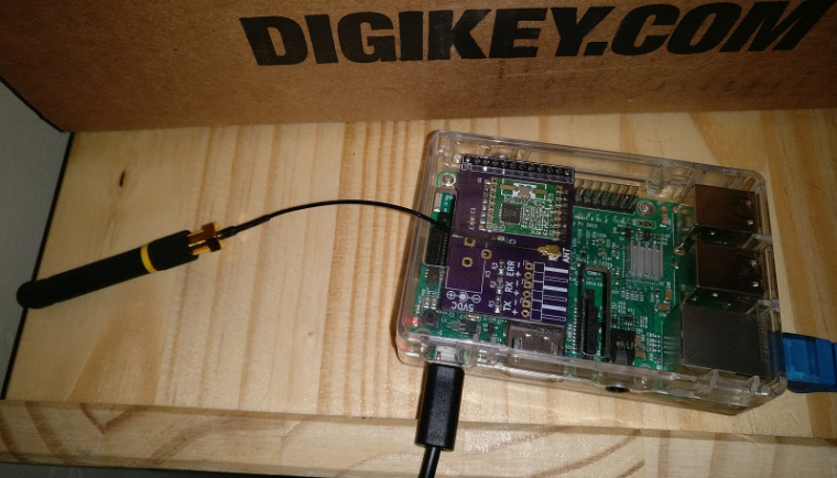
                      0_1509387688972_2017-10-30 11.14.08 - Copy.jpg

                      I soldered together the PCB I made for my RFM69 Pi Gateway. Next step is to put it in a nice enclosure

                      YveauxY 1 Reply Last reply
                      3
                      • S SquareKinematics

                        0_1509387688972_2017-10-30 11.14.08 - Copy.jpg

                        I soldered together the PCB I made for my RFM69 Pi Gateway. Next step is to put it in a nice enclosure

                        YveauxY Offline
                        YveauxY Offline
                        Yveaux
                        Mod
                        wrote on last edited by
                        #36

                        A set of Node-Red nodes to decode OpenTherm messages produced by thermostats and Central Heating systems: https://github.com/Yveaux/node-red-contrib-opentherm
                        It can e.g. replace the OpenTherm Monitor software from otgw by InfluxDB/Grafana :+1:

                        0_1509388666269_upload-a041d40e-fb40-4b6b-9c15-4bd8ec44d47f

                        Not a MySensors project, but nice anyway ;-)

                        http://yveaux.blogspot.nl

                        1 Reply Last reply
                        4
                        • NeverDieN Offline
                          NeverDieN Offline
                          NeverDie
                          Hero Member
                          wrote on last edited by NeverDie
                          #37

                          I did a quick port of my earlier project to make a breakout board for the BC832:
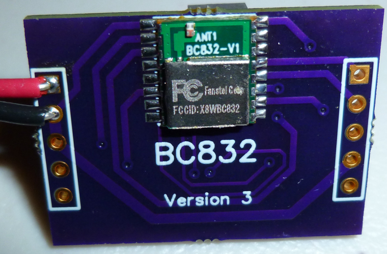
                          0_1509393019476_bc832.jpg
                          What's interesting about the BC832 is that it is a complete nRF52832 system: 32-bit ARM Cortex 4, wireless, flash, memory, RTC, and antenna, and the whole thing is smaller than a dime:
                          alt text
                          Of course, my ported breakout board, being as large as it is, doesn't do it justice. That's OK, though, because its main purpose is just to take the BC832 for a test drive.

                          1 Reply Last reply
                          2
                          • R Offline
                            R Offline
                            robosensor
                            wrote on last edited by
                            #38

                            Power (lower half) and external interfaces (upper half) PCB for my "entrance" MySensors node (unregulated voltage, +5V, +3.3V, doorbell detector, electronic door lock status, temperature, etc). I'm using conventional 220V=>6V transformers as main power supply and as simple 220V presence detector for doorbell.
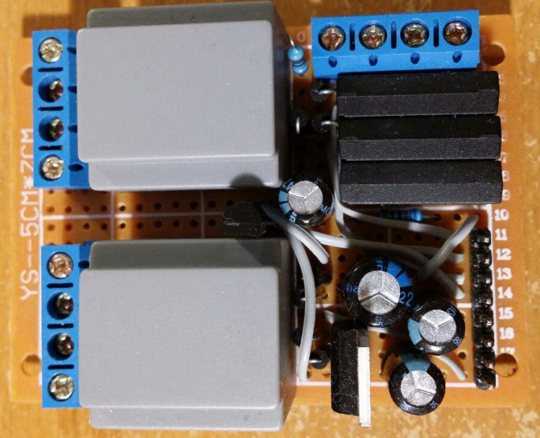
                            0_1509398995945_photo_2017-10-30_23-21-08.jpg

                            1 Reply Last reply
                            1
                            • sundberg84S Offline
                              sundberg84S Offline
                              sundberg84
                              Hardware Contributor
                              wrote on last edited by sundberg84
                              #39

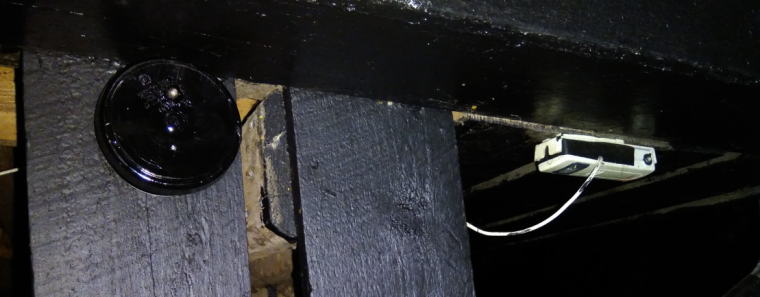
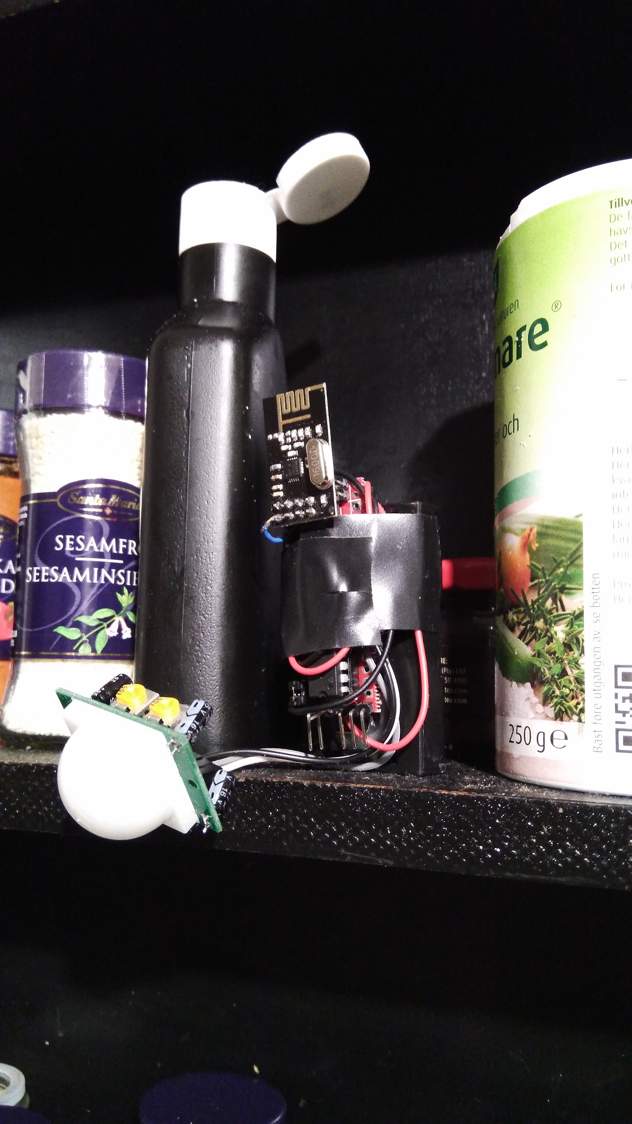
                              Let me present - How NOT to deploy a MySensors Node! Here is how you do: 1) Skrew everything solid to a wall 2) Power it up and make sure you have shorted a SDA / GND or VCC on your BMP sensor just because you dont doublecheck the colors 3)Forget to enable # My debug 4)Fetch your last BMP sensor but drop it on the lawn (pitch dark outside) 5) Spend 30min with a flashligh in 5dgr C searching for the sensor and try it out once you find it. 6) Nothing works so Un-screw everything and connect it to FTDI inside at your computer, reupload the sketch with debug. - Now everything works fine (with the first sensor) for some unknown reason. 7) Skrew everything back again! 8) Find out the BMP sensor is not working 9) Debug Serial (atleast I got to use my new logger) 10) Find out a short on the MysX connector due to bent wire.
                              0_1509477265850_upload-4cb4d2db-19b0-4c15-bb7c-85ae142145cc
                              New and old sensor - side by side.

                              0_1509477296115_upload-7e59bd8a-9c85-4db3-8a88-c86e21d1c7a4

                              Controller: Proxmox VM - Home Assistant
                              MySensors GW: Arduino Uno - W5100 Ethernet, Gw Shield Nrf24l01+ 2,4Ghz
                              MySensors GW: Arduino Uno - Gw Shield RFM69, 433mhz
                              RFLink GW - Arduino Mega + RFLink Shield, 433mhz

                              YveauxY NeverDieN 2 Replies Last reply
                              6
                              • sundberg84S sundberg84

                                Let me present - How NOT to deploy a MySensors Node! Here is how you do: 1) Skrew everything solid to a wall 2) Power it up and make sure you have shorted a SDA / GND or VCC on your BMP sensor just because you dont doublecheck the colors 3)Forget to enable # My debug 4)Fetch your last BMP sensor but drop it on the lawn (pitch dark outside) 5) Spend 30min with a flashligh in 5dgr C searching for the sensor and try it out once you find it. 6) Nothing works so Un-screw everything and connect it to FTDI inside at your computer, reupload the sketch with debug. - Now everything works fine (with the first sensor) for some unknown reason. 7) Skrew everything back again! 8) Find out the BMP sensor is not working 9) Debug Serial (atleast I got to use my new logger) 10) Find out a short on the MysX connector due to bent wire.

                                0_1509477265850_upload-4cb4d2db-19b0-4c15-bb7c-85ae142145cc
                                New and old sensor - side by side.

                                0_1509477296115_upload-7e59bd8a-9c85-4db3-8a88-c86e21d1c7a4

                                YveauxY Offline
                                YveauxY Offline
                                Yveaux
                                Mod
                                wrote on last edited by
                                #40

                                @sundberg84 poor guy... +1 for persistence though :smirk:

                                http://yveaux.blogspot.nl

                                1 Reply Last reply
                                3
                                • sundberg84S sundberg84

                                  Let me present - How NOT to deploy a MySensors Node! Here is how you do: 1) Skrew everything solid to a wall 2) Power it up and make sure you have shorted a SDA / GND or VCC on your BMP sensor just because you dont doublecheck the colors 3)Forget to enable # My debug 4)Fetch your last BMP sensor but drop it on the lawn (pitch dark outside) 5) Spend 30min with a flashligh in 5dgr C searching for the sensor and try it out once you find it. 6) Nothing works so Un-screw everything and connect it to FTDI inside at your computer, reupload the sketch with debug. - Now everything works fine (with the first sensor) for some unknown reason. 7) Skrew everything back again! 8) Find out the BMP sensor is not working 9) Debug Serial (atleast I got to use my new logger) 10) Find out a short on the MysX connector due to bent wire.

                                  0_1509477265850_upload-4cb4d2db-19b0-4c15-bb7c-85ae142145cc
                                  New and old sensor - side by side.

                                  0_1509477296115_upload-7e59bd8a-9c85-4db3-8a88-c86e21d1c7a4

                                  NeverDieN Offline
                                  NeverDieN Offline
                                  NeverDie
                                  Hero Member
                                  wrote on last edited by
                                  #41

                                  @sundberg84 Time for you to do a new PCB so you can get rid of all that wiring....

                                  sundberg84S 1 Reply Last reply
                                  1
                                  • NeverDieN NeverDie

                                    @sundberg84 Time for you to do a new PCB so you can get rid of all that wiring....

                                    sundberg84S Offline
                                    sundberg84S Offline
                                    sundberg84
                                    Hardware Contributor
                                    wrote on last edited by
                                    #42

                                    @NeverDie Im waiting for someone to create those MysX shields so I just can attach them to my EasyPCB.

                                    Controller: Proxmox VM - Home Assistant
                                    MySensors GW: Arduino Uno - W5100 Ethernet, Gw Shield Nrf24l01+ 2,4Ghz
                                    MySensors GW: Arduino Uno - Gw Shield RFM69, 433mhz
                                    RFLink GW - Arduino Mega + RFLink Shield, 433mhz

                                    NeverDieN 1 Reply Last reply
                                    1
                                    • sundberg84S sundberg84

                                      @NeverDie Im waiting for someone to create those MysX shields so I just can attach them to my EasyPCB.

                                      NeverDieN Offline
                                      NeverDieN Offline
                                      NeverDie
                                      Hero Member
                                      wrote on last edited by
                                      #43

                                      @sundberg84 Where is the definitive description of MysX? Perhaps I might have a go at making some shields with it, if I knew what it was.

                                      mfalkviddM 1 Reply Last reply
                                      0
                                      • NeverDieN NeverDie

                                        @sundberg84 Where is the definitive description of MysX? Perhaps I might have a go at making some shields with it, if I knew what it was.

                                        mfalkviddM Offline
                                        mfalkviddM Offline
                                        mfalkvidd
                                        Mod
                                        wrote on last edited by
                                        #44

                                        @NeverDie not sure if https://www.mysensors.org/hardware/mysx is definitive but it should be a good start

                                        NeverDieN 1 Reply Last reply
                                        1
                                        • mfalkviddM mfalkvidd

                                          @NeverDie not sure if https://www.mysensors.org/hardware/mysx is definitive but it should be a good start

                                          NeverDieN Offline
                                          NeverDieN Offline
                                          NeverDie
                                          Hero Member
                                          wrote on last edited by
                                          #45

                                          @mfalkvidd Wow, MYSX 2.6 is a 22 pin connector! That wouldn't be practical on a small shield (such as a pro mini size shield) I don't think.

                                          mfalkviddM 1 Reply Last reply
                                          0
                                          Reply
                                          • Reply as topic
                                          Log in to reply
                                          • Oldest to Newest
                                          • Newest to Oldest
                                          • Most Votes


                                          23

                                          Online

                                          11.7k

                                          Users

                                          11.2k

                                          Topics

                                          113.0k

                                          Posts


                                          Copyright 2019 TBD   |   Forum Guidelines   |   Privacy Policy   |   Terms of Service
                                          • Login

                                          • Don't have an account? Register

                                          • Login or register to search.
                                          • First post
                                            Last post
                                          0
                                          • MySensors
                                          • OpenHardware.io
                                          • Categories
                                          • Recent
                                          • Tags
                                          • Popular