What did you build today (Pictures) ?

-
A (long) time ago I had my own Android app which talked xmlrpc to a Python script, which talked serial with my Arduino which in his turn talked 433 Mhz to our outlets turning lights on and off. All was dandy until Android 4 came along and something stopped working security wise and we were send back into the middle ages.
Today I successfully got MySensors working enabling me to read temp/hum from a node and letting me send Elro signals into the air over 433Mhz from OpenHAB2. Now I can scale, extend and upgrade my sensors and actuators I can move forward and start improving our home.

-
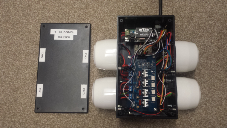
Today I completed the installation of the first of my 4 channel 240V LED light dimmers. This is installed in the roof and supports 4 buttons to turn on/off/increase/decrease each channel. It uses an AC zero crossing detector circuit and can be configured for leading or trailing edge dimming.
-
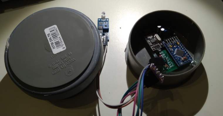
Last night I made a enclosure to my new outdoor weather station/node. It is made from 2x 70mm sewer pipe end caps and a small sewer pipe to keep them together. Works surprisingly great and looks good.
Now its painted black and drying - lets hope I can find any daylight this week and mount/deploy it.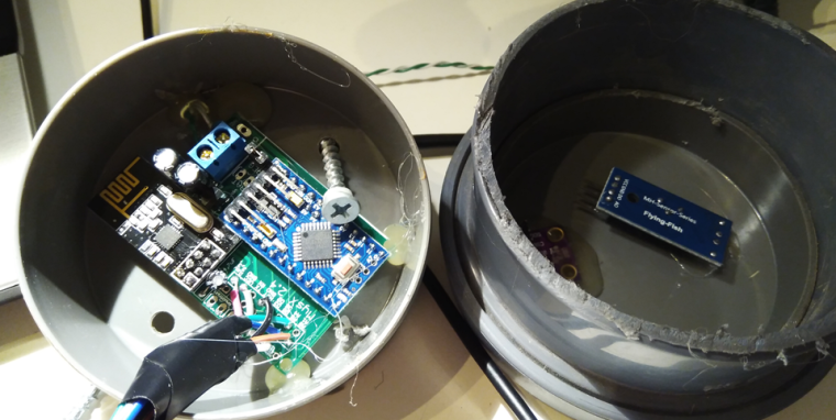
Controller: Proxmox VM - Home Assistant
MySensors GW: Arduino Uno - W5100 Ethernet, Gw Shield Nrf24l01+ 2,4Ghz
MySensors GW: Arduino Uno - Gw Shield RFM69, 433mhz
RFLink GW - Arduino Mega + RFLink Shield, 433mhz -
Last night I made a enclosure to my new outdoor weather station/node. It is made from 2x 70mm sewer pipe end caps and a small sewer pipe to keep them together. Works surprisingly great and looks good.
Now its painted black and drying - lets hope I can find any daylight this week and mount/deploy it.
@sundberg84 If this is going to be out in the sun, I would think you'd want it white. Black is going to heat up your electronics quite a bit.
Vera Plus running UI7 with MySensors, Sonoffs and 1-Wire devices
Visit my website for more Bits, Bytes and Ramblings from me: http://dan.bemowski.info/ -
@sundberg84 If this is going to be out in the sun, I would think you'd want it white. Black is going to heat up your electronics quite a bit.
@dbemowsk - No worries, no sun! All below a roof so I get shade all the day. The roof is black so I need it to blend in as well.
-
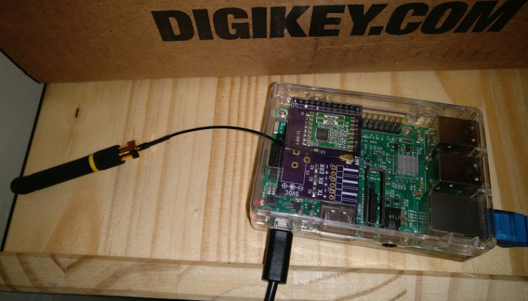
I soldered together the PCB I made for my RFM69 Pi Gateway. Next step is to put it in a nice enclosure
-
I soldered together the PCB I made for my RFM69 Pi Gateway. Next step is to put it in a nice enclosure
A set of Node-Red nodes to decode OpenTherm messages produced by thermostats and Central Heating systems: https://github.com/Yveaux/node-red-contrib-opentherm
It can e.g. replace the OpenTherm Monitor software from otgw by InfluxDB/Grafana :+1: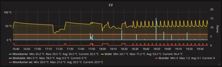
Not a MySensors project, but nice anyway ;-)
-
I did a quick port of my earlier project to make a breakout board for the BC832:
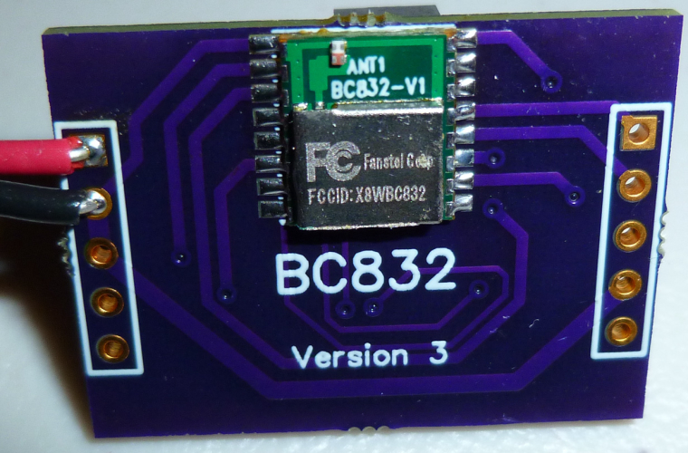
What's interesting about the BC832 is that it is a complete nRF52832 system: 32-bit ARM Cortex 4, wireless, flash, memory, RTC, and antenna, and the whole thing is smaller than a dime:

Of course, my ported breakout board, being as large as it is, doesn't do it justice. That's OK, though, because its main purpose is just to take the BC832 for a test drive. -
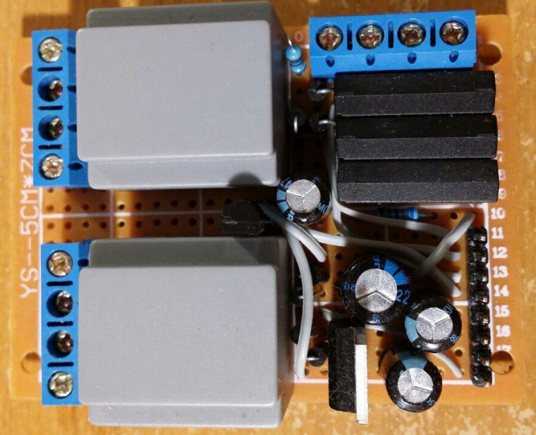
Power (lower half) and external interfaces (upper half) PCB for my "entrance" MySensors node (unregulated voltage, +5V, +3.3V, doorbell detector, electronic door lock status, temperature, etc). I'm using conventional 220V=>6V transformers as main power supply and as simple 220V presence detector for doorbell.
-
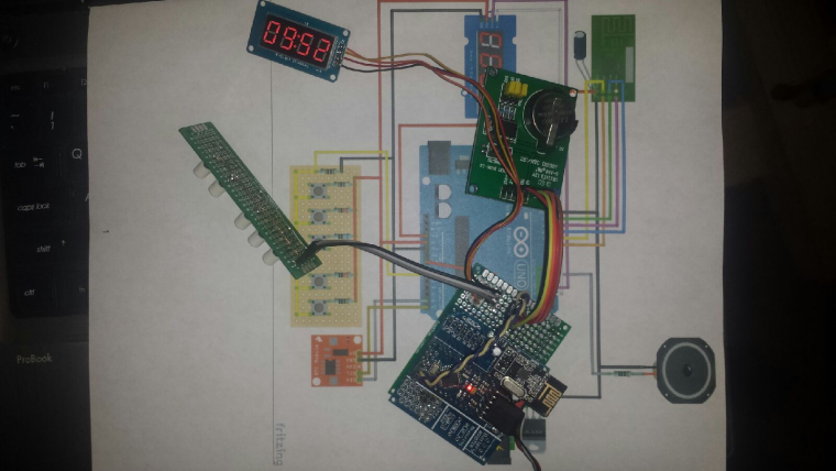
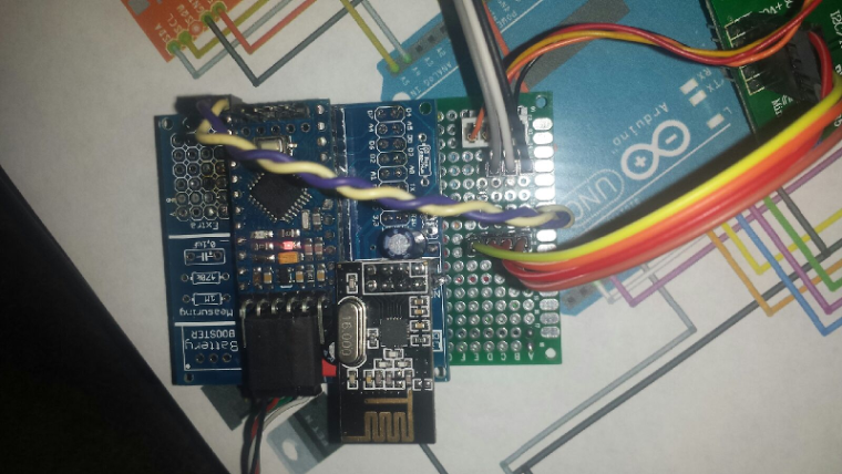
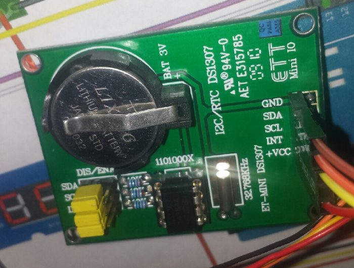
Let me present - How NOT to deploy a MySensors Node! Here is how you do: 1) Skrew everything solid to a wall 2) Power it up and make sure you have shorted a SDA / GND or VCC on your BMP sensor just because you dont doublecheck the colors 3)Forget to enable # My debug 4)Fetch your last BMP sensor but drop it on the lawn (pitch dark outside) 5) Spend 30min with a flashligh in 5dgr C searching for the sensor and try it out once you find it. 6) Nothing works so Un-screw everything and connect it to FTDI inside at your computer, reupload the sketch with debug. - Now everything works fine (with the first sensor) for some unknown reason. 7) Skrew everything back again! 8) Find out the BMP sensor is not working 9) Debug Serial (atleast I got to use my new logger) 10) Find out a short on the MysX connector due to bent wire.
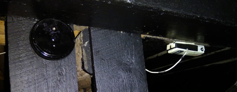
New and old sensor - side by side.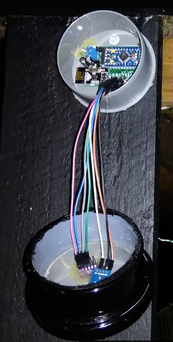
Controller: Proxmox VM - Home Assistant
MySensors GW: Arduino Uno - W5100 Ethernet, Gw Shield Nrf24l01+ 2,4Ghz
MySensors GW: Arduino Uno - Gw Shield RFM69, 433mhz
RFLink GW - Arduino Mega + RFLink Shield, 433mhz -
Let me present - How NOT to deploy a MySensors Node! Here is how you do: 1) Skrew everything solid to a wall 2) Power it up and make sure you have shorted a SDA / GND or VCC on your BMP sensor just because you dont doublecheck the colors 3)Forget to enable # My debug 4)Fetch your last BMP sensor but drop it on the lawn (pitch dark outside) 5) Spend 30min with a flashligh in 5dgr C searching for the sensor and try it out once you find it. 6) Nothing works so Un-screw everything and connect it to FTDI inside at your computer, reupload the sketch with debug. - Now everything works fine (with the first sensor) for some unknown reason. 7) Skrew everything back again! 8) Find out the BMP sensor is not working 9) Debug Serial (atleast I got to use my new logger) 10) Find out a short on the MysX connector due to bent wire.
New and old sensor - side by side. -
Let me present - How NOT to deploy a MySensors Node! Here is how you do: 1) Skrew everything solid to a wall 2) Power it up and make sure you have shorted a SDA / GND or VCC on your BMP sensor just because you dont doublecheck the colors 3)Forget to enable # My debug 4)Fetch your last BMP sensor but drop it on the lawn (pitch dark outside) 5) Spend 30min with a flashligh in 5dgr C searching for the sensor and try it out once you find it. 6) Nothing works so Un-screw everything and connect it to FTDI inside at your computer, reupload the sketch with debug. - Now everything works fine (with the first sensor) for some unknown reason. 7) Skrew everything back again! 8) Find out the BMP sensor is not working 9) Debug Serial (atleast I got to use my new logger) 10) Find out a short on the MysX connector due to bent wire.
New and old sensor - side by side.@sundberg84 Time for you to do a new PCB so you can get rid of all that wiring....
-
@sundberg84 Time for you to do a new PCB so you can get rid of all that wiring....
@NeverDie Im waiting for someone to create those MysX shields so I just can attach them to my EasyPCB.
Controller: Proxmox VM - Home Assistant
MySensors GW: Arduino Uno - W5100 Ethernet, Gw Shield Nrf24l01+ 2,4Ghz
MySensors GW: Arduino Uno - Gw Shield RFM69, 433mhz
RFLink GW - Arduino Mega + RFLink Shield, 433mhz -
@NeverDie Im waiting for someone to create those MysX shields so I just can attach them to my EasyPCB.
@sundberg84 Where is the definitive description of MysX? Perhaps I might have a go at making some shields with it, if I knew what it was.
-
@sundberg84 Where is the definitive description of MysX? Perhaps I might have a go at making some shields with it, if I knew what it was.
-
@NeverDie not sure if https://www.mysensors.org/hardware/mysx is definitive but it should be a good start
@mfalkvidd Wow, MYSX 2.6 is a 22 pin connector! That wouldn't be practical on a small shield (such as a pro mini size shield) I don't think.
-
@mfalkvidd Wow, MYSX 2.6 is a 22 pin connector! That wouldn't be practical on a small shield (such as a pro mini size shield) I don't think.
-
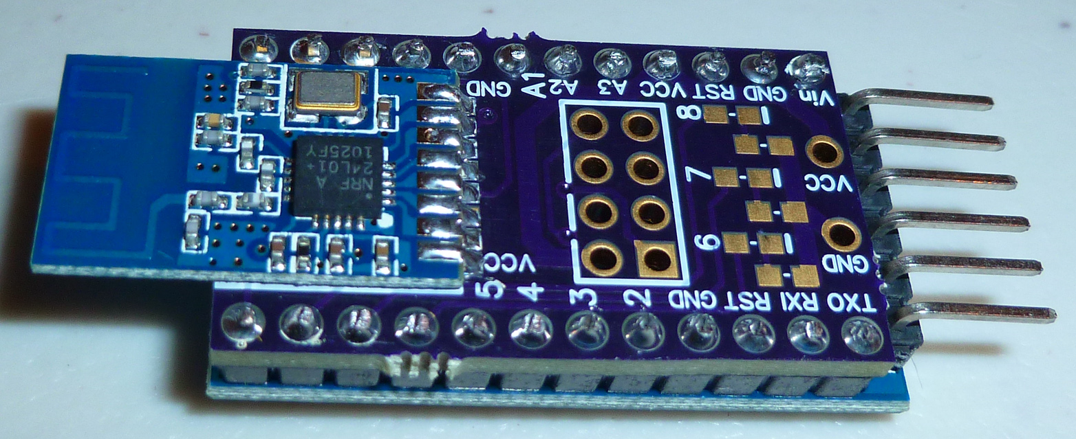
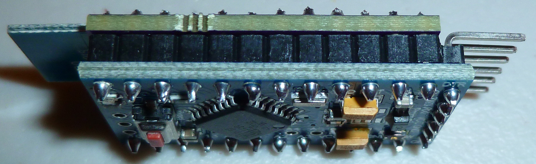
Put together this pro mini nRF24 shield for testing...