What did you build today (Pictures) ?
-
@neverdie You can also consider replicating the 1/4 wave against ground in the opposite direction perhaps?
-
@zboblamont said in What did you build today (Pictures) ?:
@neverdie You can also consider replicating the 1/4 wave against ground in the opposite direction perhaps?
I don't understand what you mean. Can you explain a bit more what that would be?
-
@neverdie Sure.
A quarter wave on an ideal Ground Plane mimics a half wave, the GP is sort of like a mirror in radio terms for the 1/4 above it....
Ergo two identical 1/4 waves, one attached to RF feed the other attached to ground, does the same thing, although in fact slightly better...
-
@zboblamont So, what you are advocating is a dipole antenna? i.e. something notionally similar to this:
https://www.openhardware.io/view/277/ESP8266-RFM69HW-gateway-with-dipole-antenna
At least, that is what it sounds like to me.
-
@neverdie Not advocating a dipole as such, only pointing to an alternative to your suggested ground plane at 90 degrees to the base of the antenna. Electrically, the second half of the dipole IS the ground plane, and vice versa.
With such physically small boards, it is virtually impossible to achieve the ideal ground plane unless the wavelength is very small, I suggested a duplicate helical tied to GND in the opposite direction to your antenna essentially accomplishes the same thing.
-
Interestingly, I just now checked, and it appears my LoRa leak detectors have even better range still. Maybe it's because GND completely encircles the PCB along all four edges. This may cause me to rethink the design of the gateway node, which up to now has been much smaller than the leak detectors....
-
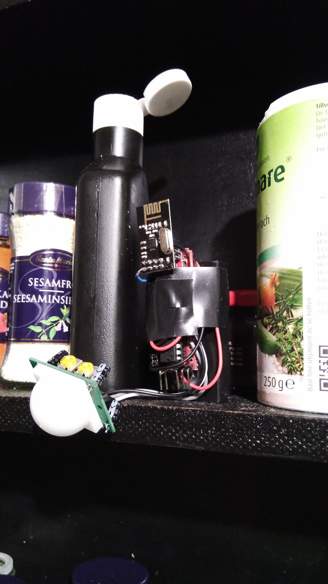
Today some maintenance on my GW.
Added a ground wire for debug and also corrected a buildmisstske and grounded the case.
And relocated (let's hope for the best) it to my new HA DIY board...
-
And there was the first failing sensor.... But was it because I changed the location on the gw? Nope... I had a temp/hum right beside the gw which I pushed so it fell on the floor...
Radio cap de-attashed and sensor died.
Easy fix and now back in operation.
-
@sundberg84 Sorry for the stupid question, but what holds your WEB/MAIL black box in place?
-
@sundberg84 said in What did you build today (Pictures) ?:
And there was the first failing sensor.... But was it because I changed the location on the gw? Nope... I had a temp/hum right beside the gw which I pushed so it fell on the floor...
You meant "the first FALLING sensor"
-
@neverdie said in What did you build today (Pictures) ?:
@sundberg84 Sorry for the stupid question, but what holds your WEB/MAIL black box in place?
Screws.
-
@sundberg84 +1 for the mySensors sticker!
-
My son and I finally finished his first MySensors project- a remote control for his room. He wasn't too interested but you have to start somewhere right...?
Question for you all... what are you doing (if anything) to vent the fumes from soldering? I haven't really been worried about it in the past but it makes me nervous with my son doing it with me.
Anyway, here are the pictures.
-
@petewill What up with the red, yellow, and blue wires on the pro mini?
Also, did you print the case with a volcano?
-
@petewill That's awesome. Did you work with him too on the design of the box? Great job.
-
@petewill I put a regular 120mm pc fan to blow the fumes sideways. Not perfect, but I think it is good enough for the short time I spend soldering.
-
@petewill is it battery powered? Can you share the code?
-
@petewill , @gohan I use the same as @mfalkvidd and its pretty much a PC fan with the wires to a 9v battery.... been thinking for a long time to make a more permanent sollution with a tubes from outside....
-
Today's test was to see if the regular reed switches can be closed by the magnetic field created by a 1A current.I got an opportunity to try out my recently USB power meter and adjustable load.
Since I am not sure how the reed switch is mounted inside the sensor, I tried different orientations but nothing triggered the sensor. I also tried 2A but that wasn't enough either.
I need a non-invasive way to know if (how much) current is flowing in a DC cable. I was hoping the reed switch would be an easy way. My next hope is something like a SCT-013, unless someone has suggestions for other sensors. Requirements: 6-48V DC. 0.5-10A. I only need to know if the circuit is consuming >0.5A, no need for an exact measurement.
-
@mfalkvidd Hall sensor?
-
@gohan SCT-013 is a hall-based sensor I think. I was looking for more specific that just the type of sensor.
-
@mfalkvidd said in What did you build today (Pictures) ?:
SCT-013 is a hall-based sensor I think.
No, it's only a current transformer, and you possibly need (at least) a burden resistor to measure the current. Ofcourse we already have a thread on it
-
@yveaux yes I've read that thread and I would choose one of the sct-013 variants that already contains a burden resistor.
-
@mfalkvidd Didn't you play with electromagnets when you were a kid? At least try coiling the wire and maybe putting a metal core inside it. Use a lot of coils. The more the better. Then maybe your reed-type switch would have a chance of seeing enough magnetism to trigger it.
-
@neverdie wouldn't that choke the current passing through the coil? He said he needs 6-48V DC. 0.5-10A
-
@NeverDie The wires are there in case I need to upload a new bootloader. This sensor one of the first ones I have done where the Arduino isn't easily removable and I wanted to try to make it a little easier in case I had to change it.
I used an original Prusa I3 MK2 to do the printing. This is in ABS (because I didn't have any white PLA) so the print is a little rougher than if it was done with PLA.@dbemowsk Thanks! No, my son didn't help with the case design (yet). It was from a previous project that I slightly modified. My son is 6 so he doesn't really have the attention span to do too much yet. I'm hoping that doing little parts of a project will be fun for him and eventually turn into full projects.
@mfalkvidd & @sundberg84 Thanks. I guess I need to rig something up if he is going to be helping me more often...
@gohan No, it's not battery powered. I didn't want to have to deal with changing batteries and there is a power outlet right near the location he wanted it. Here is the code:
/** The MySensors Arduino library handles the wireless radio link and protocol between your home built sensors/actuators and HA controller of choice. The sensors forms a self healing radio network with optional repeaters. Each repeater and gateway builds a routing tables in EEPROM which keeps track of the network topology allowing messages to be routed to nodes. Created by Henrik Ekblad <henrik.ekblad@mysensors.org> Copyright (C) 2013-2015 Sensnology AB Full contributor list: https://github.com/mysensors/Arduino/graphs/contributors Documentation: http://www.mysensors.org Support Forum: http://forum.mysensors.org This program is free software; you can redistribute it and/or modify it under the terms of the GNU General Public License version 2 as published by the Free Software Foundation. ******************************* REVISION HISTORY Version 1.0 - PeteWill */ #define SKETCH_NAME "Controller" #define SKETCH_VERSION "1.0" //Child (sensor) name that will be sent to gateway #define CONTROLLER_CHILD_NAME "Room Control" // Enable debug prints to serial monitor #define MY_DEBUG //MySensors debug messages #define LOCAL_DEBUG //Code specific debug messages // Enable and select radio type attached #define MY_RADIO_NRF24 //#define MY_RADIO_RFM69 #define MY_RF24_PA_LEVEL RF24_PA_HIGH //Options: RF24_PA_MIN, RF24_PA_LOW, RF24_PA_HIGH, RF24_PA_MAX #define MY_RF24_CHANNEL 76 #define MY_NODE_ID 1 //Manually set the node ID here. Comment out to auto assign #include <MySensors.h> #include <Bounce2.h> #define SCENE_CHILD_ID 0 #define BAUD_RATE 57600 #ifdef LOCAL_DEBUG #define dbg(...) Serial.print(__VA_ARGS__) #define dbgln(...) Serial.println(__VA_ARGS__) #else #define dbg(x) #define dbgln(x) #endif //Button Pins -- Arduino Digital I/O pin button is connected to #define BLIND_UP_PIN 5 #define BLIND_STOP_PIN 4 #define BLIND_DOWN_PIN 3 #define LIGHT_ON_PIN 8 #define LIGHT_OFF_PIN 7 #define EXTRA_BUTTON_PIN 6 #define LED_PIN A0 //Pin for the LED transistor #define FLASH_TIME 300 //Amount of time to flash the LED (in milliseconds) #define ARRAY_SIZE(x) (sizeof(x)/sizeof(x[0])) uint8_t ledOn = 0; uint32_t ledMillis; //Used for tracking the LED flash time //The sceneNum array corresponds with the buttonPins array so if a button pin is read, it will send the scene number to the gateway int sceneNum[] = {0, 1, 2, 3, 4, 5}; uint8_t buttonPins[] = { BLIND_UP_PIN, BLIND_STOP_PIN, BLIND_DOWN_PIN, LIGHT_ON_PIN, LIGHT_OFF_PIN, EXTRA_BUTTON_PIN }; //Debouncer is used for the buttons. Need to have the same number as the total buttons. Bounce debouncer[] = { Bounce(), Bounce(), Bounce(), Bounce(), Bounce(), Bounce() }; //used to keep track of previous values contact sensor values uint8_t buttonPrev[] = {1, 1, 1, 1, 1, 1}; MyMessage scene(SCENE_CHILD_ID, V_SCENE_ON); void before() { #ifdef LOCAL_DEBUG Serial.begin(BAUD_RATE); #endif } void presentation() { // Send the sketch version information to the gateway sendSketchInfo(SKETCH_NAME, SKETCH_VERSION); // Register all sensors to gw (they will be created as child devices) present(SCENE_CHILD_ID, S_SCENE_CONTROLLER, CONTROLLER_CHILD_NAME); } void setup() { //Set up Pins for (int i = 0; i < ARRAY_SIZE(buttonPins); i++) { // Setup the pins pinMode(buttonPins[i], INPUT_PULLUP); // After setting up the button, setup debouncer debouncer[i].attach(buttonPins[i]); debouncer[i].interval(100); dbg(F("Set up contact Pin: ")); dbgln(buttonPins[i]); } pinMode(LED_PIN, OUTPUT); } void loop() { uint32_t currentMillis = millis(); for (int i = 0; i < ARRAY_SIZE(buttonPins); i++) { debouncer[i].update(); // Get the update value uint8_t value = debouncer[i].read(); if (value != buttonPrev[i]) { dbg(F("Value is for sensor #")); dbg(buttonPins[i]); dbg(F(" is ")); dbgln(value); if (value == 0) { //Button is pressed send scene value send(scene.set(sceneNum[i])); ledOn = 1; ledMillis = currentMillis; } buttonPrev[i] = value; } } if (ledOn) { digitalWrite(LED_PIN, HIGH); if (currentMillis - ledMillis > FLASH_TIME) { ledOn = 0; digitalWrite(LED_PIN, LOW); } } }
-
@neverdie said in What did you build today (Pictures) ?:
@mfalkvidd Didn't you play with electromagnets when you were a kid? At least try coiling the wire and maybe putting a metal core inside it. Use a lot of coils. The more the better. Then maybe your reed-type switch would have a chance of seeing enough magnetism to trigger it.
Yes, but that would unfortunately completely defeat my purpose. The device should be easy to install (I can't expect the end-user to coil their cable) and work with cables that are designed for >10A which means they will be too thick to coil. I understand that I did not mention all aspects of the use case in my post though so thanks anyway.
-
@petewill said in What did you build today (Pictures) ?:
Question for you all... what are you doing (if anything) to vent the fumes from soldering? I haven't really been worried about it in the past but it makes me nervous with my son doing it with me.
I have a Hakko 493 clone, it has a carbon filter to absorb the smoke (or most of it) so it doesn't smell too much in the room when I need to solder for a long time and I can't open the windows. I don't have a link because I bought it in my local shop (it was cheaper than AliExpress + shipping), but you can easily find similar models or clones of the FA400 by searching "smoke absorber" on AliExpress.
-
@mfalkvidd
I had a similar requirement recently, which was determining when my CNC was finished. I decided to measure the current to decide that. It's 24VDC and might have a current as high as 6amp in a theoretical worst case, but as little as 0.5a when moving just one of the stepper motors. So, what I came up with was this, which I've tested and it works:
Basically, it uses six 5-watt 3 ohm resistors in parallel to create a 1/2-ohm sense resistor, which an arduino then measures the voltage drop across by just doing an analog read from an analog GPIO pin across a voltage divider. I don't really know your use-case, but maybe you could adapt it for your application? You can ignore the LoRa module, which in my case I use to send out a signal to a remote receiver inside my house that the CNC print job (in the garage) is done.
-
I made a MysX template for anyone who wants to create a MysX board to any EasyPCB in KiCadd.
Found here: https://github.com/sundberg84/HomeAutomation/tree/master/MysX template EasyPCB
-
@nca78 thanks! I'll check that out.
-
Today I made and assembled a board which instantiates the schematic I posted above two days ago on this thread:
Basically, it sends a wireless signal as soon as the CNC machine finishes its work.
-
My old Yamaha YSP-1100 soundbar just decided to die.
After some searching I found the problematic capacitor. A 22uF 600V had dropped to 6uF....
!
-
@hek How did you find the faulty capacitor?
-
@NeverDie, well, I started my trouble shooting with a lucky google search. For old devices like this, you are often not the first person experiencing a problem.
-
I had a good laugh when examining the other board. Is this a normal solution for remote-in?
-
-
@hek If this is for a sound bar, I know on some older stereos they had a remote signal out that you could tie into other components in the system. Maybe it's something like that.
-
@neverdie could you achieve something similar with a sonoff pow measuring the whole cnc power consumption?
-
@gohan I don't know, as I'm not familiar with Sonoff, or how sensitive it is.
-
It's a WiFi power meter with a relay to turn off the load, so you could set a rule on controller that if measured power goes below a certain amount it will notify something
-
It's a very good suggestion. If I wasn't already done, I'd try it. If it works, the Sonoff would be simpler and less effort.
-
Another hour on my... whatever it is.
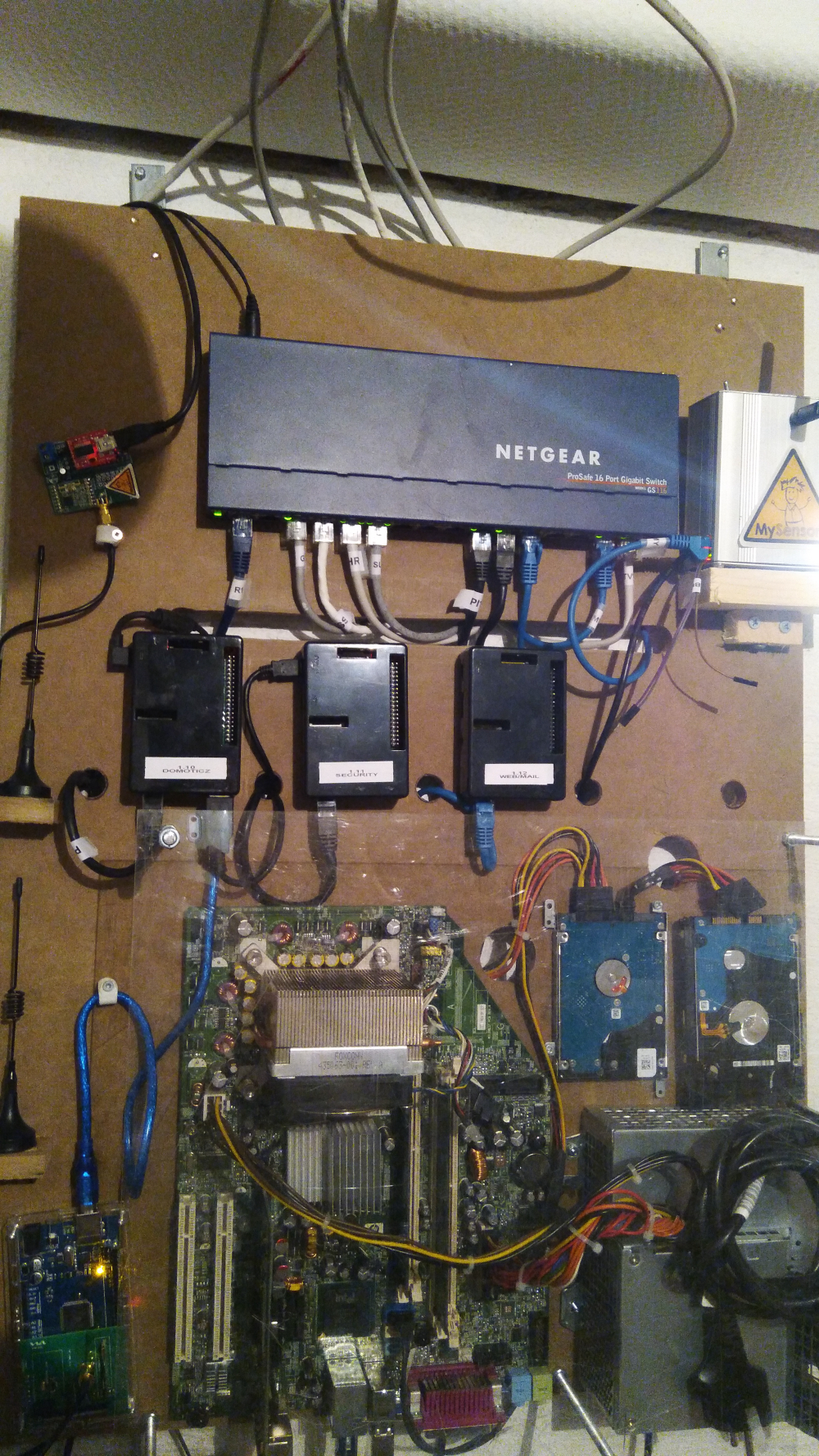
Anyone that can recommend a open source router (hardware) or cheap hardware for pfsense which isn't that big and draws that watt amount.
-
WHat do you need a PC for?
-
@gohan it's a pc with my intention to run pfsense (open source router) but it is old and draws to much power for my taste.
-
How much power does that pc draw?
Mine:
Asrock Q1900B-ITX + pico 12V to atx psu + PCIE Intel Nic 2/4 Gbit ports + SSD can run on 20W or less, but I believe the J1900 Celeron lacks AES for VPN if you care about it.HP DL 380 G7 2xL5640 hex core, 144GB Ram, 4xGbit Nics, SSD, 90W at idle (99.9% of time) and pfsense is only one of the VMs I constantly run, besides OH2, Ubiquity controller, Nextcloud. The ability to snapshot a development VM, or fork (clone) it is a killer feature for me.
Another DL 380 G7 in standby is drawing 15W.
Phu*ck I have some old shitty switches that draw 30-40W, not to mention security cameras, 300-500Wh during the night for all my crazy home automation&security.
-
@sundberg84 not cheap but 15W (at max load): https://www.aliexpress.com/item/Pfsense-Hardware-Qotom-Barebone-Mini-PC-Nano-itx-Core-i7-4500U-Fanless-Mini-Computer-X86-Router/32799048185.html
Cheaper alternatives:
https://www.aliexpress.com/store/product/2015-new-arrival-direct-selling-bay-trail-J1800-mini-pc-windows-8-1-Qotom-linux-2G/108231_32285025655.html max 10W
https://www.netgate.com/solutions/pfsense/sg-1000.html 2.5W idle
-
the little netgate looks cute, but wondering if it would be enough powerful (for streaming etc.)
@sundberg84
when you already have parts laying around, like ram, hdd etc, you could also use intel J3355 or J4205 cpus, maybe better than J1800. J3355 boards are not expensive. Then add a pcie NICs or a simple usb to gigabit..
I would choose micro atx board because often cheaper, same for ram (more compatible ref vs itx boards sometimes are restrictive), and it may be more flexible for pcie slot. That is, if size is not a concern.Or maybe a more powerful cpu, if you plan to factorize lot of things in VMs etc.
In both case it could also allow you to save power by decreasing number of rpis for example. But an interesting math would be pros&cons between features, power consumption saving, cost of a more expensive setup vs years for ROI about power savings (if that is the point)
Maybe we'll see new mini pc router in future with new sbc and mcus..
-
@sundberg84 you could have all the rpi's running on the pc hardware, and save a couple of pennies on the electricity bill..
I exchanged my HA rpi with an atom based machine, as it had 4Gb ram. Now I'm using docker to containerize the different parts of my setup (influxdb, grafana, domoticz, nodered, moquitto, etc.). Ok, it uses a bit more power, but not that much compared to the flexibility that I have now. So now I have a lot of "machines" for handling the different parts.. I can even spin up an experimental domoticz in seconds (I'm playing with mqtt for backbone in my HA setup, instead of mysensors serial protocol, and a lot of http calls to different parts of my system.
-
You take for granted everybody knows how to work with docker
-
I didn't know how to work with docker 2 months ago.. If I can learn it, others can do it too It's not that complicated after all
-
Some weeks ago I made a video with my children and i had this idea to do something with electronics... so mostly as a testproject I made a introduction video for EasyPCB. I kinda like it... but my English isnt the best in some places.
Easy/Newbie PCB for MySensors – 08:01
— Andreas Sundberg
-
I built a GPIO interface for the Raspberry PI using @GertSanders PCB (link)
I ordered the PCB via OSH Park, successfully soldered 2 and my setup is now much cleaner without these jumper cables.
For the second one, I soldered the NRF directly on the PCB (just because I wanted to gain some height), and everything works flawlessly.Big thank to @GertSanders for his PCB!
My gateway runs mysgw, Mosquitto and Node-Red.
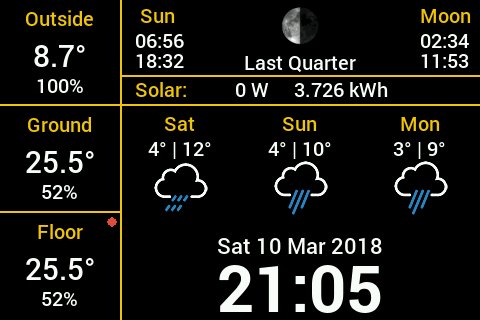
In the back is my Raspberry Dashboard displaying the weather, info from my solar installation and the sensors MQTT messages.
-
@sburlot Can't help but see your weather display in the background. What platform is that?
-
I made this LoRa shield for an Arduino Pro Mini:
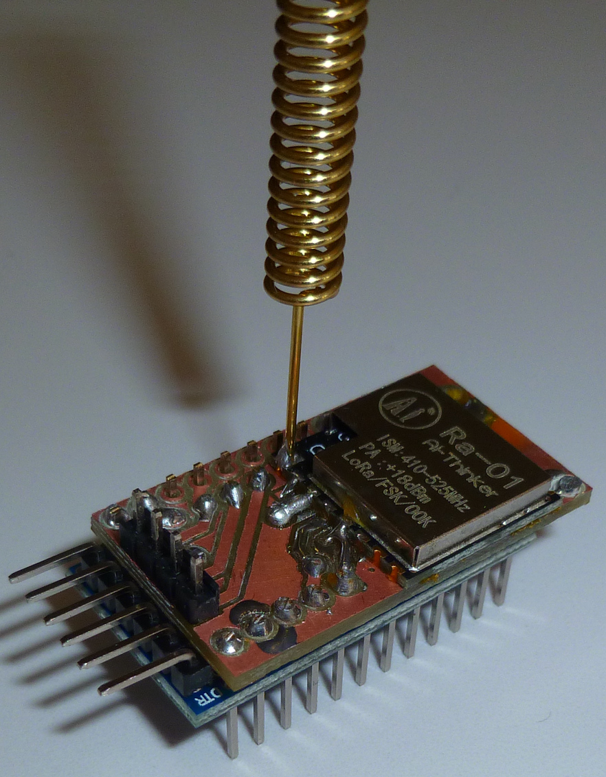
I like it because of the small form factor and because it preserves access to all of the Pro Mini pins. i.e. you can plug it in just like a Pro Mini.
I also gave it 4 header pins for an Si7021 TH sensor, which I haven't yet attached.
-
@dbemowsk
It's a Raspberry 3, with a cheap 480x320 screen, and a Python+PyGame script.Start of my script comes from this script
Temp+Humidity comes from mySensors SenseBender Micro via NodeRed/MQTT
Solar power comes from my inverter via a script (also MQTT)
Weather from WeatherUnderground
-
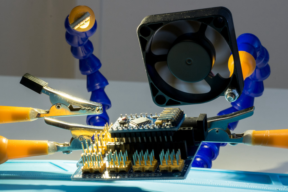
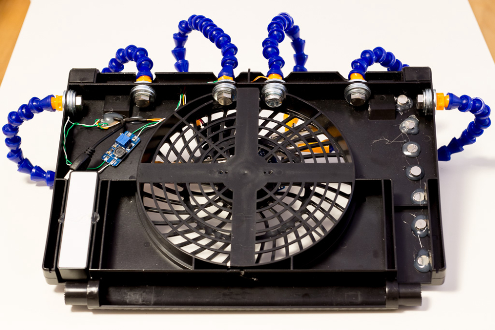
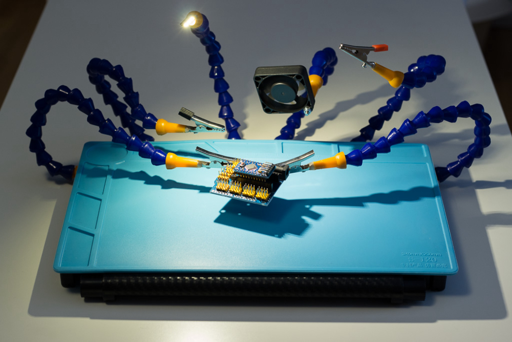
not built today, but someone mentioned fumes extractor, so this is what I built for soldering, light and fume extractor are powered by a small usb rechargeable powerbank. Fan has a active carbon filter behind it and works great for small to medium-ish projects I work on
-
@dakipro Very creative! Thanks for sharing. I've seen those flexible hose things before in other contexts, but I don't know the name. What is the term?
-
-
@neverdie Don't they use something like that on CNC machines for the coolant?
-
@dbemowsk Yup.
-
Thanks. About the cnc pipes, just check if they are US or EU threads, as I was initially planning to fasten them with nuts, but couldn't find any US type in scandinavia. So I had to improvise with A LOT washers and heavy screws as seen in the picture. For the base I used old laptop cooling holder (whatever the name is).
And it works surprisingly well for what I use it, I was expecting it to have a bouncing effect, but it is not that much noticeable.
Way better then that ebay crappy holder with big magnifying mirror that is just so flimsy and annoying.
I was planing to dedicate one hose as a solder feeder, but never bothered with it.Light is a touch-to-adjust type, very very practical , something like this
https://www.ebay.com/itm/5X-6-LED-Night-Light-Soshine-USB-Power-1W-5V-Touch-Dimmer-Warm-White-Light-B2L8/282772437504?epid=721587756&hash=item41d68cfa00:g:gZQAAOSw1cNaMlr5I also have a switch for a fan on the side, and a volt stepup as the fan works on 12V (9 or 10 is my setting).
I have glued the magnets on the right on the last photo, they are then actually on the left of the silicone mat where the "compartments" are
-
@dakipro What hose diameter do you recommend? I'm guessing larger diameters will be stiffer than smaller diameters, but that's only just my uninformed guess.
-
@dakipro that's really nice, I have bought pipes and clips, but didn't find a suitable base yet. Good idea to use a battery too, it avoids an additional cable.
-
Another EasyPCB video - a complete build of a 5v node with a radiotest and cleareeprom.
Complete build! - Easy/Newbie PCB (Nrf24l01+) for MySensors – 15:44
— Andreas Sundberg
-
@neverdie i think i have the larger ones, but with 3-4$ pricetag one can easily order both and use what works best (or even combine them for more flexibility). I originally planned on using only 4 pipes, but then I figured why not put them all, they will just lie around anyway. Now I have two clamps orientated horizontally and two vertically for easier mounting.
Battery bank is I winner I think, it is very very practical and holds several hours.
Even if it goes flat during the project, it is just to plug everything into the wall charger, as one would have to do anyway.
-
here is photo my usb gateway with STM32 power
it's a big difference with arduino nano
-
and that's a TV box turn into a mini pc more powerful than raspberry pi 3
and I installed linux with domoticez and imperihome EMMC Flash is fluid and fast
and toutsca works well8 x CPU: Amlogic S912 Octa core ARM Cortex-A53 CPU jusqu'à 2GHz (DVFS)
GPU: 750MHz + ARM Mali-820MP3 GPU Processeur
RAM: 3Go DDR3
ROM: 32Go EMMC Flash
Système d'exploitation: Android 6.0
Ethernet: 100M/1000M
WIFI: 2.4GHZ / 5.8GHZ 802.11a / b / g / n / Ac
Bluetooth: BT4.1
-
Not working on hardware at the moment, but I am still "building" things with mysensors.. Recently I have been moving all my homeautomation to docker containers, and also moving stuff towards using MQTT as a backbone transport.
Right now I have moved automation rules from domoticz to nodered, after which I have "killed" domoticz (the only reason why I had been keeping it alive, was because it handled some of my automation rules for turning tv / amplifier on when chromecast was active etc).
Together with my chromecast "surveilance python service" I get notifications on MQTT when any of my two chromecasts starts an app / pause/ play etc. The python program also has a MQTT listener, so I can send pause/play etc. to my chromecasts over mqtt. And even throw a stream to it over mqtt.
Today I made a universal control endpoint, so I can send pause/play etc. to a single mqtt topic, and then nodered directs it to the active chromecast, or to my dvd player if that is the active in the current scene.
In the end everything should play together with a dashboard that I have made in angular5 (rewriting it at the moment to use MQTT instead of various http calls)
The plan is that the dashboard is on a wallmounted tablet, acting as a simple dashboard / weather station, where one can control basic things in the livingroom (start streaming of specific Radio / TV channels among other things).
The nodered project can be found here, if anyone would like to have a look..
-
@tbowmo
Quite cool, what is your reason behind to move away from Domoticz and go all in on node-red?
-
I guess because you can do pretty much everything you want instead of being bound to what Domoticz can do
-
I have been using influxdb/grafana for the last year or so, for logging data and presenting it, so no need to use domoticz for that. Over a year ago I injected nodered into the stream, so it sits between mysensors and domoticz, and was used to route things around (And make some fake sensors for domoticz).
For the dashboard part I have been developing my own solution. First it was running within domoticz as a customized dashboard, but I moved it to Angular instead, with a strong dependency towards domoticz, as I could query that to get sensor values. Lately I had moved on to use MQTT for the dashboard (and internal node-red data routing). There I can get persistent data (retain) that keeps the latest data on a given topic. Then my need for domoticz went away there..
The last thing I then used domoticz for, was the automation rules for turning on / off my tv when the chromecast was activated, and control a couple of LED strips according to the state of the chromecast (playing / paused etc). With that moved to nodered, then domoticz could be turned off.
The complete software stack is a bit larger, than with domoticz for everything, but it is much more flexible, than what I could achieve with domoticz.
also it brought in a couple of needed updates for my node-red mysensors nodes, so that was a "bonus" as well
-
@tbowmo interesting indeed, tnx for sharing. Currently I still use Domoticz for the API Logging is done with INFLUX and Grafana. However in addition to Domoticz I use Pass2PHP. I can now control everything with PHP. PHP seems pretty common so a lot of examples I can find online ;-0. I am a complete MQTT / NODE-RED NOOB.
-
@sincze said in What did you build today (Pictures) ?:
I am a complete MQTT / NODE-RED NOOB.
So start playing with it to become a Node-Red/MQTT Fanboy!
-
It is always those last connections...
-
@sincze well you're half way there, already got influxdb implemented
NodeRed is pretty easy to work with, and MQTT is (almost) just start and forget with mosquito. Just a messaging channel that you can hook any listener into, like python scripts, angular5 web apps etc.
-
Today I built auto-detection of missing MySensors keywords. The build system will complain if someone adds a new keyword to the Doxygen documentation but forgets to add it to keywords.txt.
This is what the output looks like on the current code base (we're missing a bunch of keywords):
This is the code change:
I have also added those missing keywords to keywords.txt, so now they'll be highlighted properly in the Arduino IDE.
Thanks to Anticimex for assisting me in working with the build system.
-
One more build for today: building the raspberry pi gateway.
I often need to test different settings for the Raspberry Pi Gateway. Running make after just changing one parameter in the configure command (for example, turning on or off interrupts for nrf24 or changing the PA_LEVEL) results in a 1m 13s wait on my Raspberry Pi:
I installed ccache using these instructions and now a make with the same type of change is done in 31s.
Not that much of a win, but it saves a lot of time when trying many different settings.
-
did you cut the compile time of the gateway?
-
@gohan yes?
-
@mfalkvidd on my Pi3 it takes 40 around seconds, are you using an old Pi1 ?
-
@gohan no, I'm using a Pi3.
-
Today I finally got my thumbs out and upgraded my plant monitoring to MySensors 2.x (from 1.x).
Updated sketch is available on Github: https://github.com/mfalkvidd/arduino-plantmoistureResult: I really need to water my plants But the 2.5 year old batteries are still going strong.
-
Tonight some more PCB design:
-
@sundberg84 I will throw my two cents in on the design. An issue that I had brought up on previous revisions had to do with capacitors. On the Rev 9 and below boards, your capacitor footprints were pretty much all for flat ceramic capacitors. While I was able to make it work for the couple can style electrolytics that I used, it wasn't quite right. Now on this revision, I see that all of your capacitors have a can electrolytic style footprint. I think it needs to be a mix. The 4.7uf and 10 uf capacitors should be can style footprint, whereas your 0.1s should be non polarized ceramic flat cap footprints. The flat pack ceramics I think have a wider hole spacing.
Again, just my two cents
-
@dbemowsk the positive with polarized footprint is that you can use both and it's very easy for a newbie to see which one is Gnd. You who are more experienced can determine if you want to use a flat unpolarized cap.
-
This evening I spent a few hours finding more MySensors keywords that exist but weren't highlighted.
I found about 20 that were documented but not highlighted, so I added them.I also found 3 that weren't documented nor highlighted. I have created issues on github to document them. Help is welcome. Documenting the keywords is an easy way to contribute to the project.
https://github.com/mysensors/MySensors/issues/1090
https://github.com/mysensors/MySensors/issues/1089
https://github.com/mysensors/MySensors/issues/1088
-
@sundberg84 one of the 0.1uf caps that i use has short leads and wouldn't fit that hole spacing. They are higher voltage capacitors that i bought years ago for another project that i am trying to use up. I do see your point though.
-
@mfalkvidd said in What did you build today (Pictures) ?:
Today I finally got my thumbs out and upgraded my plant monitoring to MySensors 2.x (from 1.x).
Updated sketch is available on Github: https://github.com/mfalkvidd/arduino-plantmoistureResult: I really need to water my plants But the 2.5 year old batteries are still going strong.
What kind of components is this running on? I am having trouble getting my batteries to run even 2.5 months (or 2.5 weeks for the outside temp sensor...)
-
@maghac see the link in my post for full details. But basically it is just what's recommended on the battery page. Arduino pro mini with power led and ldo removed, bod set to 1.8V, powered by 2xAA.
-
This post is deleted!
-
-
@thucar what display do you use and where did you buy it? What library did you use?
-
@dirkc the display is a JLX12864-378 off a chinese “component tester” kit I had available. Using the u8g2 library to run it.
-
Today I built a led dimmer and motion detector for my kitchen. Running on 12v and a led list of about 2m.
Everything is built on my MysX led board and it was so easy to assemble everything and it's really small.
I have documented this project and will show you in a video when edited.
-
Today I built a new Ethernet Gateway.
Using a Freetrionics Ethermega - Fixed SPI bus, so no soft SPI and I can use MY_RX_MESSAGE_BUFFER_FEATURE. PoE, improved voltage regulator design so I can run the amplified NRF24 with MY_RF24_PA_LEVEL RF24_PA_HIGH.
Under the radio is a small prototyping area with capacitor for the radio and an ATSHA204A - because one day I swear I will implement signing.
Slightly modified Gateway sketch that writes successful DHCP IP addresses to EEPROM. I assign a static address on my router. If there's a power failure, the gateway will start up with last address - router takes ages to come online.
Fired up the X-carve to cut the aluminium chassis, which has added benefit of shielding the NRF radio as well. The complicated cutout on the front was to allow air intake for the fan. Was supposed to just be a grille, but after a couple of beers I got too cute for my own good. Took 2 hours to cut that.
-
A video of my Ledstrip project in the kitchen:
MySensors LED Strip Dimmer - EasyPCB (Nrf24l01+) and Led Board. – 19:12
— Andreas Sundberg
-
Today I have finished work on control center for my smart home. The box includes a Raspberry Pi 3, gateway, ethernet switch, power supplies 5V and 9V. Audio input jack, ethernet and AC line cabels out from the box. Maybe, a GSM module should be included to the free space too (i will thinking about...). I am going to install this box in the near future.
-
@kalina said in What did you build today (Pictures) ?:
ione di installare questa scatola
if I can know !! The audio socket what is it for ???
-
@sindrome73 said in What did you build today (Pictures) ?:
The audio socket what is it for ???
For connecting the audio system to the RPI3