What did you build today (Pictures) ?

-
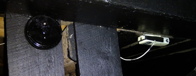
Last night I made a enclosure to my new outdoor weather station/node. It is made from 2x 70mm sewer pipe end caps and a small sewer pipe to keep them together. Works surprisingly great and looks good.
Now its painted black and drying - lets hope I can find any daylight this week and mount/deploy it.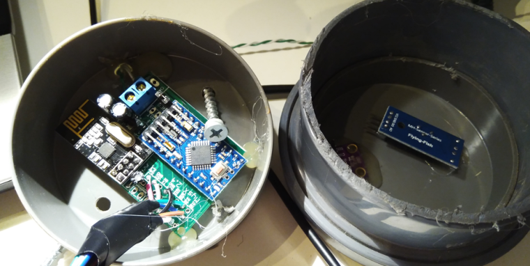
@sundberg84 If this is going to be out in the sun, I would think you'd want it white. Black is going to heat up your electronics quite a bit.
Vera Plus running UI7 with MySensors, Sonoffs and 1-Wire devices
Visit my website for more Bits, Bytes and Ramblings from me: http://dan.bemowski.info/ -
@sundberg84 If this is going to be out in the sun, I would think you'd want it white. Black is going to heat up your electronics quite a bit.
@dbemowsk - No worries, no sun! All below a roof so I get shade all the day. The roof is black so I need it to blend in as well.
-
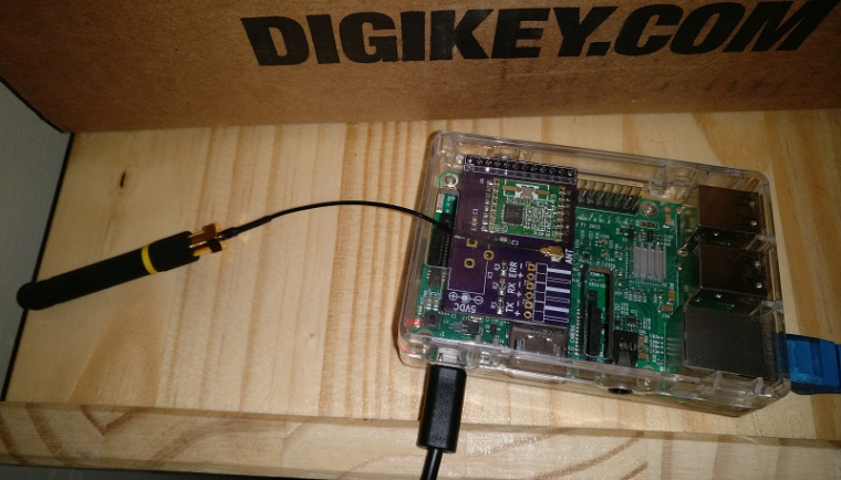
I soldered together the PCB I made for my RFM69 Pi Gateway. Next step is to put it in a nice enclosure
-
I soldered together the PCB I made for my RFM69 Pi Gateway. Next step is to put it in a nice enclosure
A set of Node-Red nodes to decode OpenTherm messages produced by thermostats and Central Heating systems: https://github.com/Yveaux/node-red-contrib-opentherm
It can e.g. replace the OpenTherm Monitor software from otgw by InfluxDB/Grafana :+1: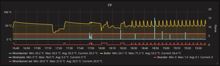
Not a MySensors project, but nice anyway ;-)
-
I did a quick port of my earlier project to make a breakout board for the BC832:
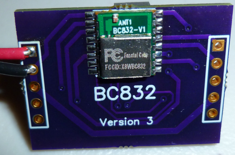
What's interesting about the BC832 is that it is a complete nRF52832 system: 32-bit ARM Cortex 4, wireless, flash, memory, RTC, and antenna, and the whole thing is smaller than a dime:

Of course, my ported breakout board, being as large as it is, doesn't do it justice. That's OK, though, because its main purpose is just to take the BC832 for a test drive. -
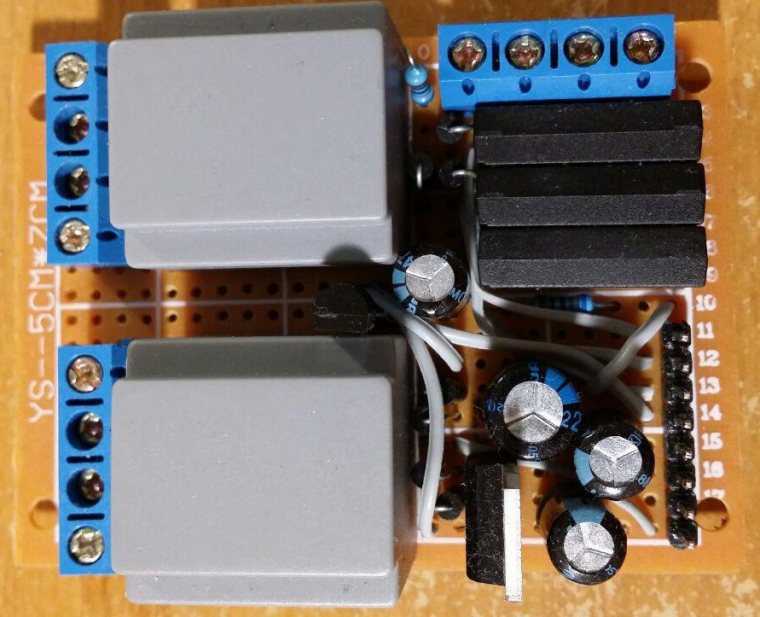
Power (lower half) and external interfaces (upper half) PCB for my "entrance" MySensors node (unregulated voltage, +5V, +3.3V, doorbell detector, electronic door lock status, temperature, etc). I'm using conventional 220V=>6V transformers as main power supply and as simple 220V presence detector for doorbell.
-
Let me present - How NOT to deploy a MySensors Node! Here is how you do: 1) Skrew everything solid to a wall 2) Power it up and make sure you have shorted a SDA / GND or VCC on your BMP sensor just because you dont doublecheck the colors 3)Forget to enable # My debug 4)Fetch your last BMP sensor but drop it on the lawn (pitch dark outside) 5) Spend 30min with a flashligh in 5dgr C searching for the sensor and try it out once you find it. 6) Nothing works so Un-screw everything and connect it to FTDI inside at your computer, reupload the sketch with debug. - Now everything works fine (with the first sensor) for some unknown reason. 7) Skrew everything back again! 8) Find out the BMP sensor is not working 9) Debug Serial (atleast I got to use my new logger) 10) Find out a short on the MysX connector due to bent wire.
New and old sensor - side by side.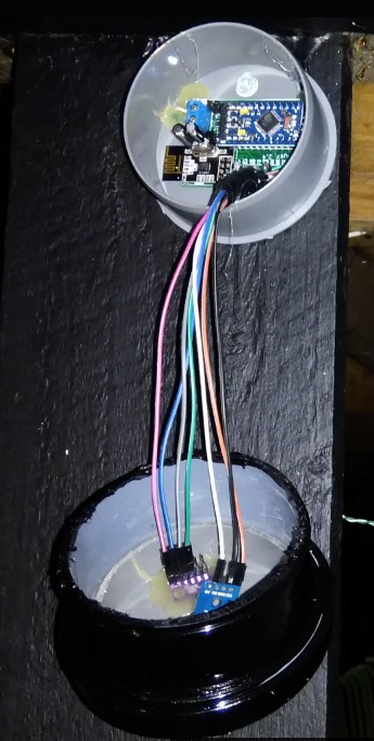
Controller: Proxmox VM - Home Assistant
MySensors GW: Arduino Uno - W5100 Ethernet, Gw Shield Nrf24l01+ 2,4Ghz
MySensors GW: Arduino Uno - Gw Shield RFM69, 433mhz
RFLink GW - Arduino Mega + RFLink Shield, 433mhz -
Let me present - How NOT to deploy a MySensors Node! Here is how you do: 1) Skrew everything solid to a wall 2) Power it up and make sure you have shorted a SDA / GND or VCC on your BMP sensor just because you dont doublecheck the colors 3)Forget to enable # My debug 4)Fetch your last BMP sensor but drop it on the lawn (pitch dark outside) 5) Spend 30min with a flashligh in 5dgr C searching for the sensor and try it out once you find it. 6) Nothing works so Un-screw everything and connect it to FTDI inside at your computer, reupload the sketch with debug. - Now everything works fine (with the first sensor) for some unknown reason. 7) Skrew everything back again! 8) Find out the BMP sensor is not working 9) Debug Serial (atleast I got to use my new logger) 10) Find out a short on the MysX connector due to bent wire.
New and old sensor - side by side. -
Let me present - How NOT to deploy a MySensors Node! Here is how you do: 1) Skrew everything solid to a wall 2) Power it up and make sure you have shorted a SDA / GND or VCC on your BMP sensor just because you dont doublecheck the colors 3)Forget to enable # My debug 4)Fetch your last BMP sensor but drop it on the lawn (pitch dark outside) 5) Spend 30min with a flashligh in 5dgr C searching for the sensor and try it out once you find it. 6) Nothing works so Un-screw everything and connect it to FTDI inside at your computer, reupload the sketch with debug. - Now everything works fine (with the first sensor) for some unknown reason. 7) Skrew everything back again! 8) Find out the BMP sensor is not working 9) Debug Serial (atleast I got to use my new logger) 10) Find out a short on the MysX connector due to bent wire.
New and old sensor - side by side.@sundberg84 Time for you to do a new PCB so you can get rid of all that wiring....
-
@sundberg84 Time for you to do a new PCB so you can get rid of all that wiring....
@NeverDie Im waiting for someone to create those MysX shields so I just can attach them to my EasyPCB.
Controller: Proxmox VM - Home Assistant
MySensors GW: Arduino Uno - W5100 Ethernet, Gw Shield Nrf24l01+ 2,4Ghz
MySensors GW: Arduino Uno - Gw Shield RFM69, 433mhz
RFLink GW - Arduino Mega + RFLink Shield, 433mhz -
@NeverDie Im waiting for someone to create those MysX shields so I just can attach them to my EasyPCB.
@sundberg84 Where is the definitive description of MysX? Perhaps I might have a go at making some shields with it, if I knew what it was.
-
@sundberg84 Where is the definitive description of MysX? Perhaps I might have a go at making some shields with it, if I knew what it was.
-
@NeverDie not sure if https://www.mysensors.org/hardware/mysx is definitive but it should be a good start
@mfalkvidd Wow, MYSX 2.6 is a 22 pin connector! That wouldn't be practical on a small shield (such as a pro mini size shield) I don't think.
-
@mfalkvidd Wow, MYSX 2.6 is a 22 pin connector! That wouldn't be practical on a small shield (such as a pro mini size shield) I don't think.
-
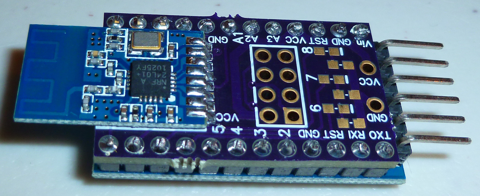
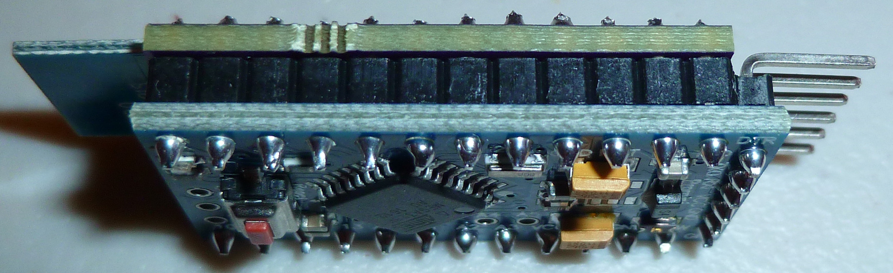
Put together this pro mini nRF24 shield for testing...
-
@shabba said in What did you build today (Pictures) ?:
Where you get pcb?
https://www.openhardware.io/view/480/Compact-nRF24L01-Pro-Mini-Bottom-Shield
-
I just now put together the final test configuration:
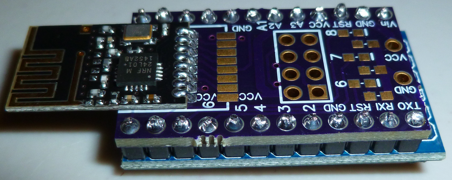
It's meant to be a "universal" shield that can accept any of the most common nRF24L01 modules, whether they be SMD or the 8-pin variety.
What I want people to know though is that as nice and compact as it is, it's actually much larger and not even as capable as the new nRF51 or nRF52 series. For instance, this nRF51 is quite affordable, and yet is both much smaller, is more energy efficient, and generally packs far more capability (including better range) than an atmega328p+nRF24L01 combo:
https://www.aliexpress.com/item/nRF51822-04-BLE4-0-Wireless-Bluetooth-Module-TTL-Low-Power-Consumption/32832511551.html?ws_ab_test=searchweb0_0&aff_platform=aaf&cpt=1509659805775&sk=rvbiMby&aff_trace_key=624250e1222041ebad3af56b86b62771-1509659805775-02431-rvbiMby&terminal_id=29bfb7ff18284b7f96acb3c3884390ce
The way I see it, there's not really much reason to continue using the nRF24L01's, except maybe already existing familiarity.[Edit: the one area that the nRF24L01's do still hold an edge, though, is in pricing on the PA+LNA versions. Some of those are still comparatively inexpensive compared to what's currently available in PA+LNA nRF5x series.
Luckily, the above shield will work with them too. :) ] -
One advantage to the "atmega328p+nRF24L01 combo" is the simplicity of choices. A pro-mini is pretty much a pro-mini, etc. Having so many choices makes it hard for a beginner with nrf51.
I really appreciate the recommendation for a reasonably priced nrf51 that can be used for battery powered nodes. Can I also ask for a recommendation on a piece of hardware to program it? (Again, lots of choices).
Thanks ahead of time.