What did you build today (Pictures) ?

-
@mfalkvidd Not a bad idea. I could get a CO2 canister with a solenoid valve and hook it to a hose that would blow CO2 directly onto the flame to put it out. Since my 3D printer is in an enclosure, it should contain the CO2 helping further extinguish the flame.
-
Cool setup, is the adapter system stable enough for the different tools? Mainly the extruder for the 3d printing?
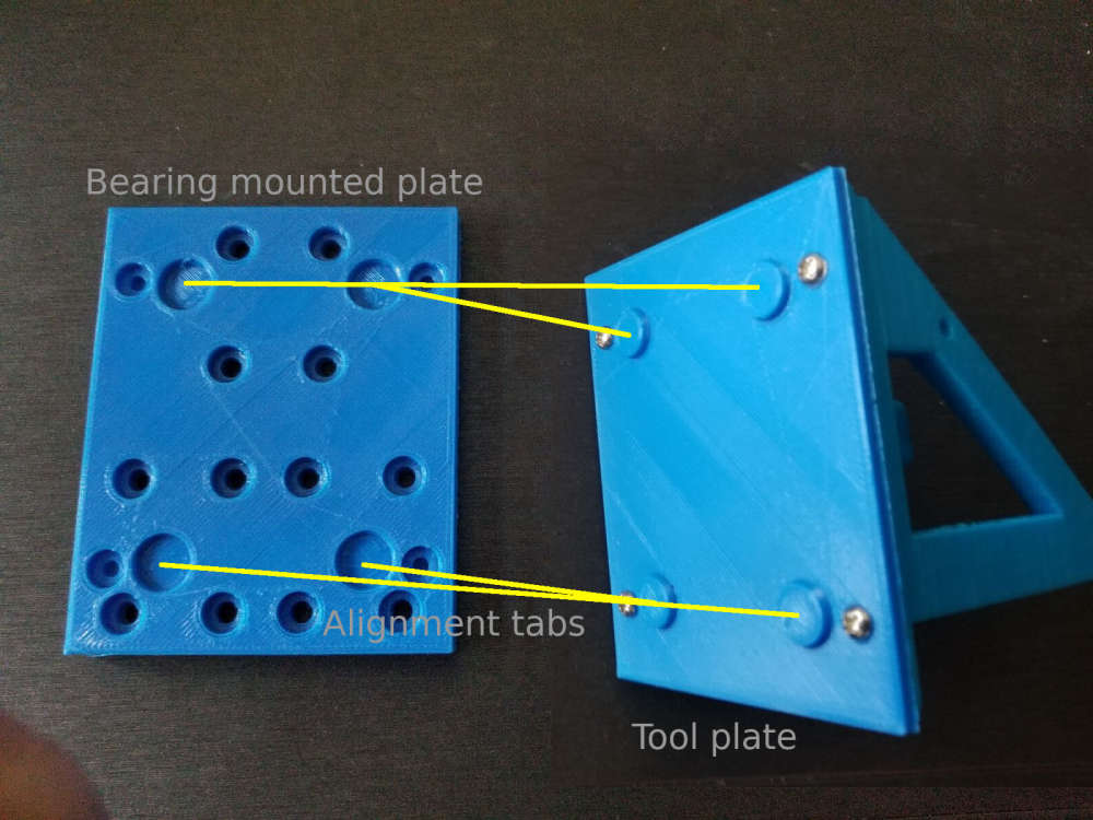
@tbowmo With the 4 recessed indents on the plate, it centers the tool being mounted pretty good. I have printed a number of things with it since the upgrade and haven't had any issues with it yet. The Makerbot Replicator series of printers use a similar way of attaching their Smart Extruder heads with the 4 magnets in the corners.
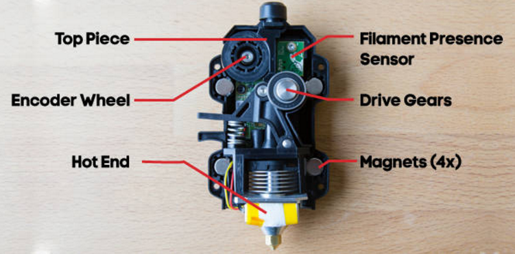
One difference between the Makerbot extruders and my setup is that the Makerbots put their extruder stepper behind the hot end assembly and that mates to the motor with a castle nut type assembly.
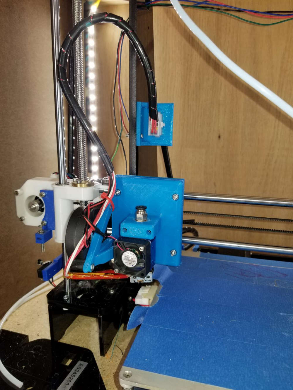
My setup uses a Bowden extruder setup that is mounted at the top of my enclosure.
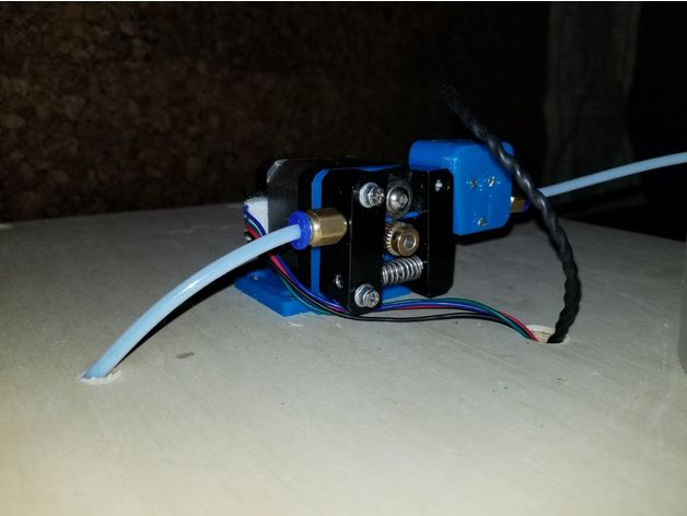
With no stepper on my hot end, that takes the majority of the weight off of the carriage. This is one of the first tests of the 3D printer head.
https://www.youtube.com/watch?v=PGpMOA4mhyI -
One extra question, what type of filament did you use to print the adapter plates in?
-
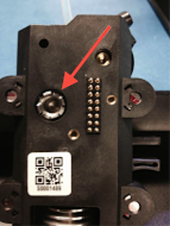
So for some time now I have been working on a conversion to my 3D printer to allow me to change between different tool heads easily, thus increasing the versatility of the machine. To jump right in and give a little background on the mod, I have a plate that mounts to my X carriage that has 4 10mm neodymium magnets in it. These magnets hold the tool in place that will be used which also has 4 magnets in it's mounting plate.
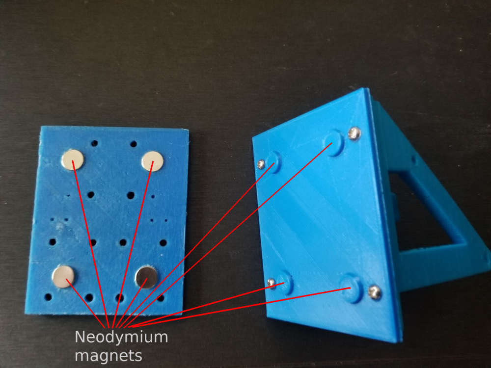
The first tool that I did was my 3D printer head. I obviously did that one first because I would need that to make future parts and tool heads to expand the machine. Here is my 3D printer head mounted to the working assembly.
Another tool head that I made for this is my simple pen plotter tool for drawing.
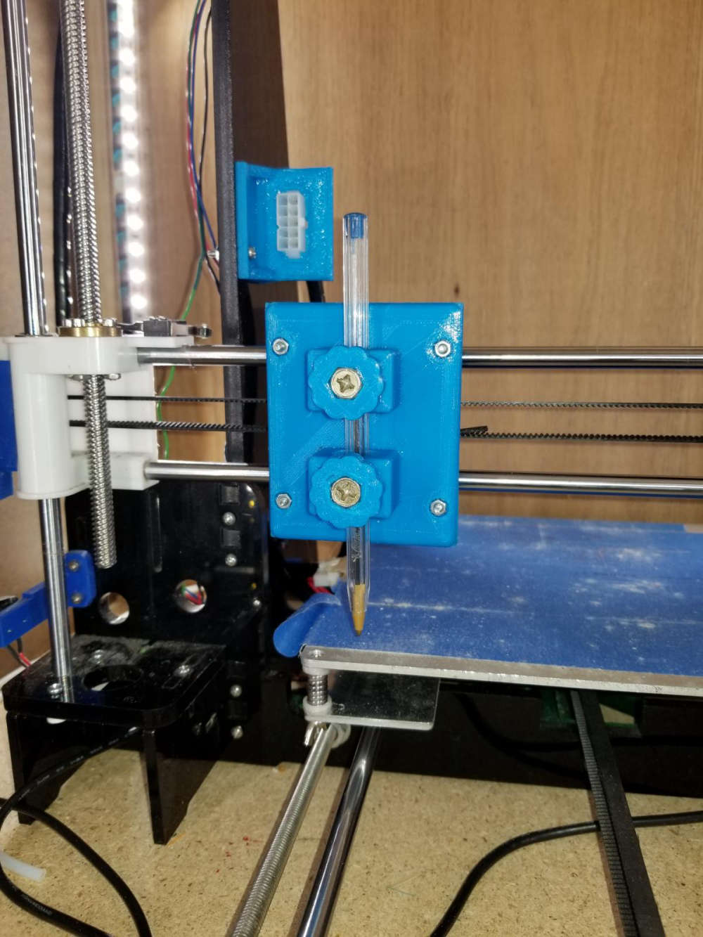
Here is a sample of something I did with the pen plotter using fine point sharpie markers. The left is the original image, and the right was done with the plotter.

The most recent tool head that I did was my laser engraver tool. This tool is the main reason for this post. This is the 6 watt laser module mounted to the carriage.
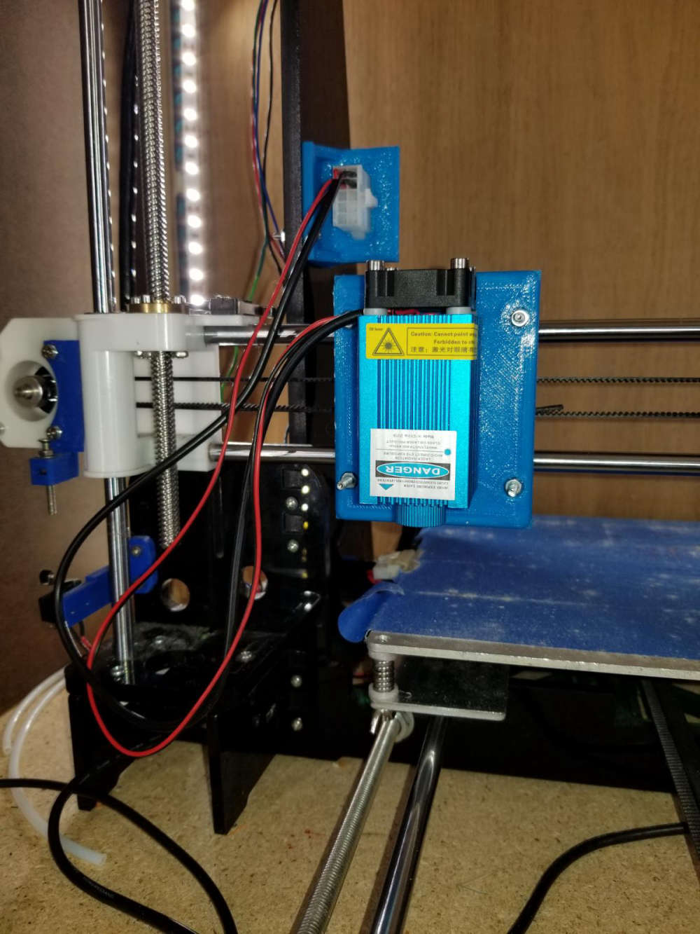
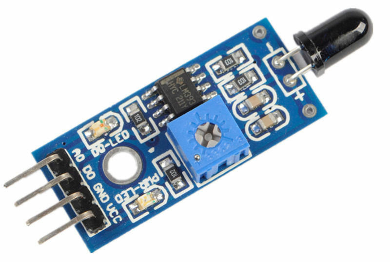
So what I am looking to do with this on the MySensors end of things is to build some sort of flame sensor that can monitor the engraving operation to indicate a small fire and take some sort of action, and also report it to my vera controller. Exactly what action I would have it take I have not figured out yet. If anyone has suggestions I'm all ears. I was thinking of something that could easily extinguish the small flame. As for the flame sensor, I know they make these small flame sensor modules, but I don't know how reliable they are, ore even how they work.
For anyone interested, here is a sample engraving on a piece of thin plywood. The left image is the original. The center is at a low resolution, and the right one was at a high resolution.

One other thing that I want to test with this is I've seen people that make circuit boards with these. They spray a layer or two of paint on their blank copper clad and then laser etch their pattern on the painted surface. Then they run it through their ferric chloride or other etching solution. Finally, sand off the layer of paint.Any suggestions or help people can give is greatly appreciated. Thanks for viewing.
For anyone interested in my 3D printer mod for using different tools, I posted it on thingiverse.
https://www.thingiverse.com/thing:3407486 -
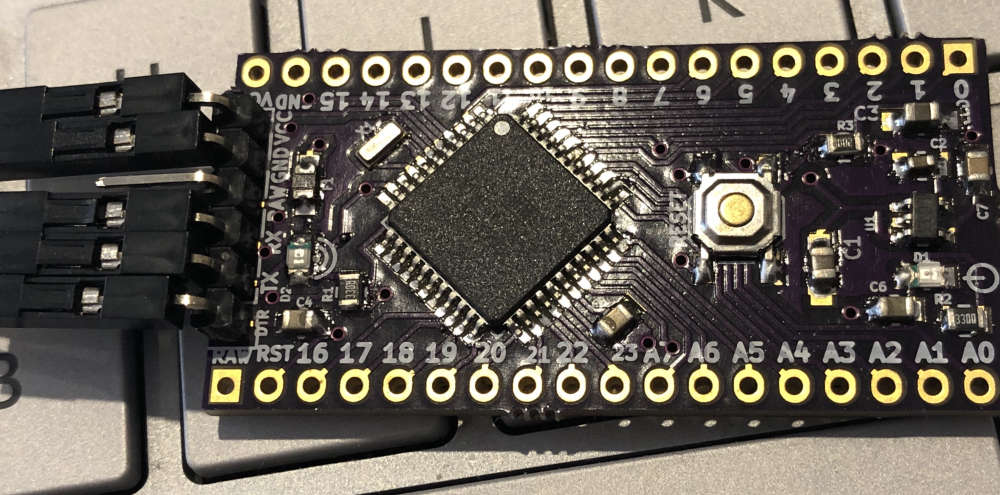
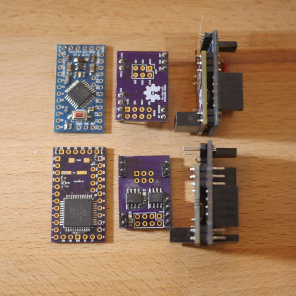
Built a 1284(p) into a 328p Pro Mini footprint. Not sure what to call it, a Pro Mini XL maybe?
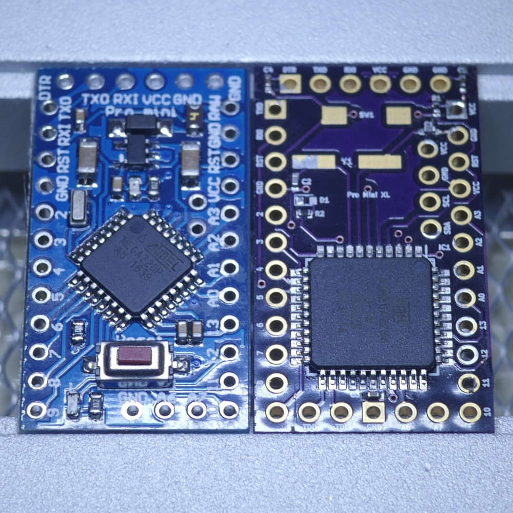
I now have x4 the program memory (128K vs. 32K), x4 the EEPROM (4K vs. 1K) and x8 the SRAM (16K vs. 2K) all in a 328p Pro Mini pin-compatible (I think!) footprint of about same size.
I can also run at 20MHz vs. the usual 8MHz provided I’m prepared to run it at 4.5v and above.
Had to sacrifice a few pins and components, but might be able to put various selections back in future revisions. Nothing major (in my opinion) just components associated with the regulator really. I also went for a crystal (not installed yet, on order, LEDs too..) over a resonator - just a personal preference for when timing is critical.
And yes, those are 0402 SMDs. I actually did them by hand (!) with a microscope and a judicious amount of coffee; a fine-point iron, solder wick and flux became my best friends.
So far, I’ve had it working with nRF24s and RFM69s radios, ATSHA for personalization and external flash for FOTA. The DualOptiboot bootloader code and makefile needed a bit of tweaking, but nothing major.
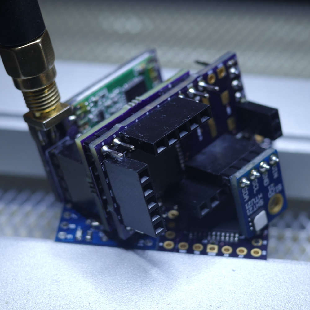
I broke out the JTAG I/F but haven’t played with that yet and also added power pins next to the I2C to make some of the sensor modules (like SI7021) pluggable - see below.
I also want to play with the QTouch library support for built-in capacitive touch buttons, sliders, etc.
Why not just go with an ARM (STM32, SAMD, nRF52)?
I’m working on it! ;o)
Am not wanting to start a(nother) 8-bit vs. 32-bit discussion. I’ve got an AliExpress package of 32-bit MCUs coming (very) slowly to me. When it arrives, I’ll start experimenting and exploring - probably with the nRF52s, since those seem to be the flavor-of-the-month and very capable-looking chips...
But until then, I need more program memory!
(Among other things…) -
Built a 1284(p) into a 328p Pro Mini footprint. Not sure what to call it, a Pro Mini XL maybe?
I now have x4 the program memory (128K vs. 32K), x4 the EEPROM (4K vs. 1K) and x8 the SRAM (16K vs. 2K) all in a 328p Pro Mini pin-compatible (I think!) footprint of about same size.
I can also run at 20MHz vs. the usual 8MHz provided I’m prepared to run it at 4.5v and above.
Had to sacrifice a few pins and components, but might be able to put various selections back in future revisions. Nothing major (in my opinion) just components associated with the regulator really. I also went for a crystal (not installed yet, on order, LEDs too..) over a resonator - just a personal preference for when timing is critical.
And yes, those are 0402 SMDs. I actually did them by hand (!) with a microscope and a judicious amount of coffee; a fine-point iron, solder wick and flux became my best friends.
So far, I’ve had it working with nRF24s and RFM69s radios, ATSHA for personalization and external flash for FOTA. The DualOptiboot bootloader code and makefile needed a bit of tweaking, but nothing major.
I broke out the JTAG I/F but haven’t played with that yet and also added power pins next to the I2C to make some of the sensor modules (like SI7021) pluggable - see below.
I also want to play with the QTouch library support for built-in capacitive touch buttons, sliders, etc.
Why not just go with an ARM (STM32, SAMD, nRF52)?
I’m working on it! ;o)
Am not wanting to start a(nother) 8-bit vs. 32-bit discussion. I’ve got an AliExpress package of 32-bit MCUs coming (very) slowly to me. When it arrives, I’ll start experimenting and exploring - probably with the nRF52s, since those seem to be the flavor-of-the-month and very capable-looking chips...
But until then, I need more program memory!
(Among other things…) -
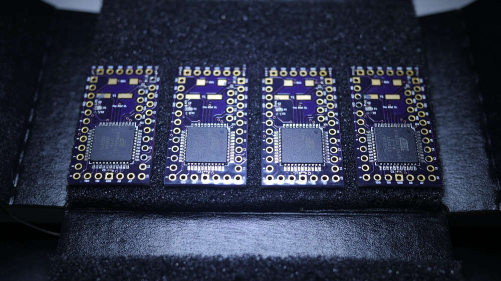
@acb I have built similar board.
The only downside is the cost and size of Atmega1284p is just so prohibitive. Yet it is 8 bits processor. I have only one fully conpleted board and a few blank pcbs.
That looks awesome @alexsh1!
Nicely laid out and cleanly soldered. Was that with an iron or hot air (or both)? Nice clear silk too; I like the power and “signal” symbols. Did you ever try a FOTA update with it? Or a low power/speed profile?
I see you went a bit wider and longer than the standard Pro Mini, (I’m assuming) to get at all the pins and add the extra regulator, LEDs, etc.
I was constrained by needing something that fit the same footprint for existing boards I already had, e.g. other “motherboards” I’d made similar to @sundberg84’s excellent Easy/Newbie PCB or wanting pin-compatibility for stacking boards like the ATSHA+EEPROM+Radio+ICSP one below:
I tried routing with the chip at a 45 degree angle too but couldn’t get a DRC to pass with the pads so close to the PTHs. I may try again with shorter (custom) TQFP pads...
Re: 1284p’s downsides of cost and size.
I know. I ended up justifying it to myself this way:
We can all get cheap 328p Pro Minis from Ali for around $2. The vast majority of my Pro Mini projects are battery powered, so there’s some “labor cost” to disable the power LED and remove the regulator. But regardless, I certainly can’t make myself a low(er) power Pro Mini for $2 - the OSH Park PCB alone is probably close to that.
I think the cheapest I ever got 1284p chips for was around $2.50, again from Ali. My “Pro Mini XL” PCBs were around $1.70 from OSH Park, add a sprinkling of 0402s, etc. and we’re probably at around $5.
I couldn’t find any 1284p-based boards near that price. The closest I got was Kevin’s Mini Duino, which is another lovely looking board, but doesn’t fit my need for a Pro Mini-constrained size and pin-compatibility. Essentially, I was after something close to a drop-in replacement.
So, $2+ versus $5+ for all the benefits (at least as far as I was concerned) listed above? It became a bit of a no-brainer.
And on the low power front, I profiled the MySensors library sleep command on it at around 5uA on 4.5v @ 20MHz using an external full swing, around 4uA on 3v @ 8MHz and around 3uA on 1.8v @ 1MHz Internal RC Osc:
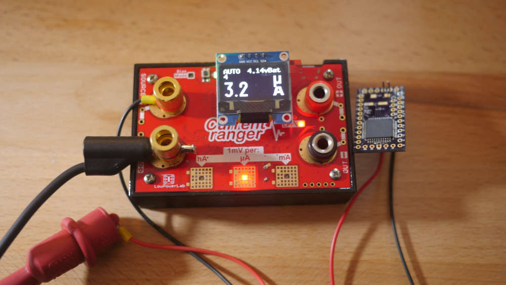
Those numbers are certainly good enough for all my current applications - no pun intended! ;)
But I would like to look at the 32-bit contenders as potential replacements.
I’ve seen nRF52s with 512K for around $2 on Ali, so maybe I’ll try my hand at a Pro Mini nRF52 or something similar eventually. The board above was a fun challenge, and afterall is what this is (mainly) about for me.
-
Built a 1284(p) into a 328p Pro Mini footprint. Not sure what to call it, a Pro Mini XL maybe?
I now have x4 the program memory (128K vs. 32K), x4 the EEPROM (4K vs. 1K) and x8 the SRAM (16K vs. 2K) all in a 328p Pro Mini pin-compatible (I think!) footprint of about same size.
I can also run at 20MHz vs. the usual 8MHz provided I’m prepared to run it at 4.5v and above.
Had to sacrifice a few pins and components, but might be able to put various selections back in future revisions. Nothing major (in my opinion) just components associated with the regulator really. I also went for a crystal (not installed yet, on order, LEDs too..) over a resonator - just a personal preference for when timing is critical.
And yes, those are 0402 SMDs. I actually did them by hand (!) with a microscope and a judicious amount of coffee; a fine-point iron, solder wick and flux became my best friends.
So far, I’ve had it working with nRF24s and RFM69s radios, ATSHA for personalization and external flash for FOTA. The DualOptiboot bootloader code and makefile needed a bit of tweaking, but nothing major.
I broke out the JTAG I/F but haven’t played with that yet and also added power pins next to the I2C to make some of the sensor modules (like SI7021) pluggable - see below.
I also want to play with the QTouch library support for built-in capacitive touch buttons, sliders, etc.
Why not just go with an ARM (STM32, SAMD, nRF52)?
I’m working on it! ;o)
Am not wanting to start a(nother) 8-bit vs. 32-bit discussion. I’ve got an AliExpress package of 32-bit MCUs coming (very) slowly to me. When it arrives, I’ll start experimenting and exploring - probably with the nRF52s, since those seem to be the flavor-of-the-month and very capable-looking chips...
But until then, I need more program memory!
(Among other things…)@acb Nice pro mini sized 1284 boards. These would work nice in my in-wall OLED scene controller boards. The standard 328 pro minis really limit what I can do with the OLED display when using it with the MySensors library. I could get more use out of the graphics end of the display with something like that.
Do you have these on OpenHardware.io? Can fully functional boards be purchased somewhere? I would be interested in trying a few out if possible.
Kudos on the design.
Vera Plus running UI7 with MySensors, Sonoffs and 1-Wire devices
Visit my website for more Bits, Bytes and Ramblings from me: http://dan.bemowski.info/ -
@acb Nice pro mini sized 1284 boards. These would work nice in my in-wall OLED scene controller boards. The standard 328 pro minis really limit what I can do with the OLED display when using it with the MySensors library. I could get more use out of the graphics end of the display with something like that.
Do you have these on OpenHardware.io? Can fully functional boards be purchased somewhere? I would be interested in trying a few out if possible.
Kudos on the design.
Thanks for the kudos, @dbemowsk. Right back at you for your scene controllers; I’m trying to get into 3D design myself, but can’t justify the time commitment right now.
Re: Do you have these on OpenHardware.io?
No, sorry, that would require me to be far more organized than I am at present! ;)
Maybe if there was enough interest, I could justify putting in the time to clean things up enough to publish… But it is valentines today, so any tinkering will surely be met with an icy stare if I try it tonight! :o
Re: Can fully functional boards be purchased somewhere? I would be interested in trying a few out if possible.
Really? I’ve never done something like that before. You do realize these are very much “alpha” right? I mean, I’ve tested the majority of the pins, but nothing like proper production hardware verification or anything. Having said that, it’s not like there’s anything complicated going on.
I managed to dig out four spares this afternoon that I’m not using from the last batch I made - how many would you like?
Three have a 1284p attached and one has the regular 1284 - I believe the only difference is the 1284 doesn’t have BOD, but I normally turn that off anyway for a (probably) miniscule power saving. I haven’t installed the crystal oscillator or reset switch yet. I don’t normally do that until I know what the use-case is. I believe I have enough spare 16MHz and 20MHz ones to fit (maybe some 8s) and some SMD reset switches too.
The only other thing would be the bootloader. I could flash the standard MySensors DualOptiboot?
So, if you (or I suppose anyone else for that matter) are interested, just shoot me a chat message via my profile and we can figure things out off-thread, as this is a bit off-topic now.
Thanks again for the interest - even if you don’t buy - made my day! :)
-
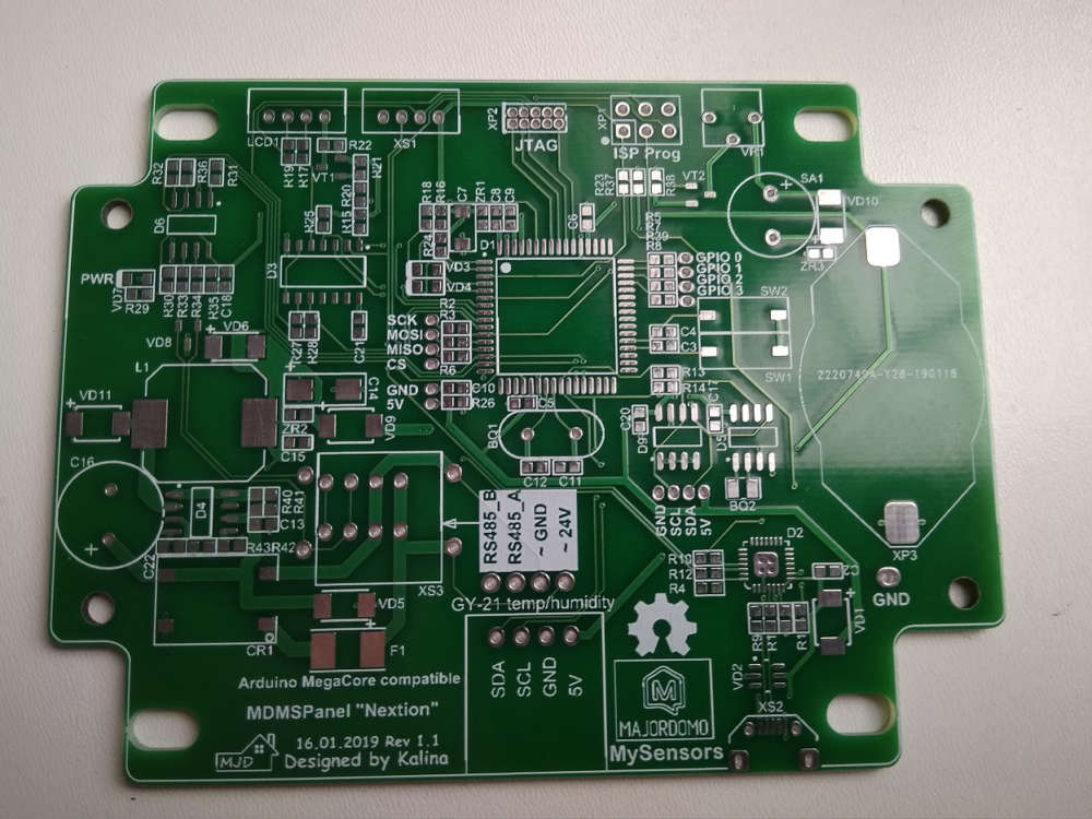
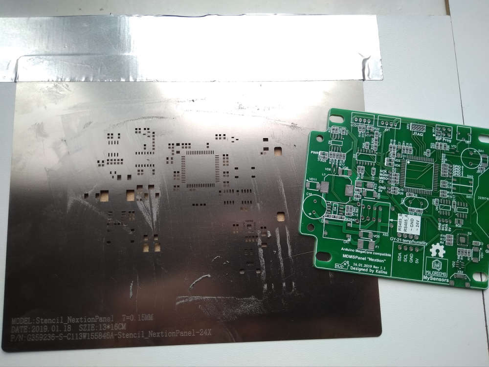
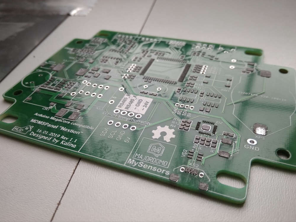
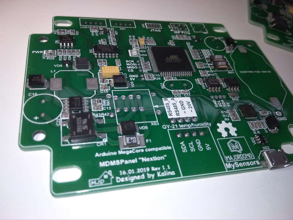
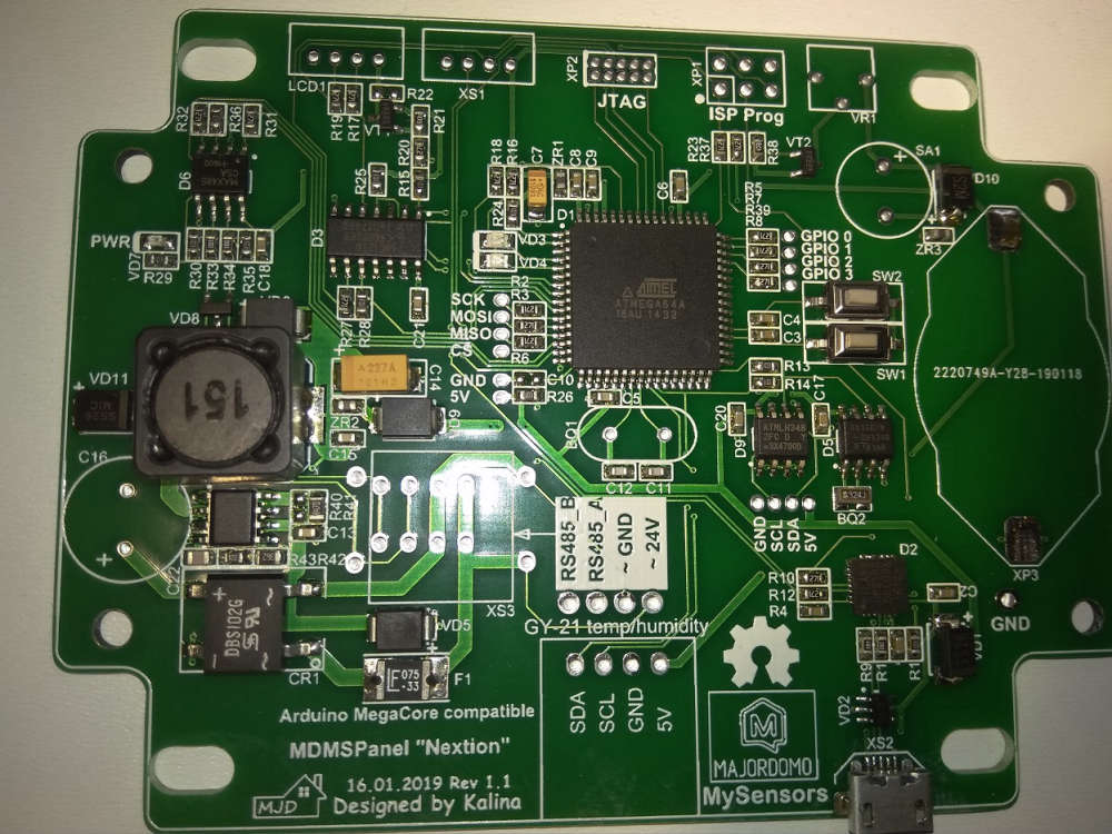
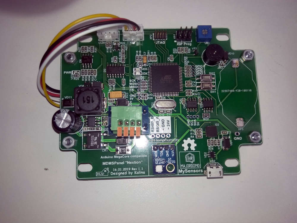
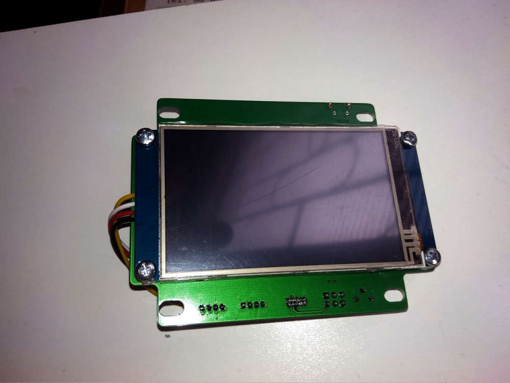
Some photos of my new device - MDMSPanel "Nextion". I have finished soldering an hour ago)) Next week i will public this project.
-
Some photos of my new device - MDMSPanel "Nextion". I have finished soldering an hour ago)) Next week i will public this project.
@kalina
Looks good, however due to EMC I strongly recommend to add a GND groundplane on your PCB. I would myself have TOP layer as +DC and BOT layer as GND, this provide less power "sparks" on the tracks and a "capacitor" effect on whole PCBhttps://en.wikipedia.org/wiki/Ground_plane#/media/File:TerraTec_G3_circuit_board_2.jpg
https://www.quora.com/What-is-the-importance-of-a-ground-plane-of-a-PCB?share=1
-
Some photos of my new device - MDMSPanel "Nextion". I have finished soldering an hour ago)) Next week i will public this project.
-
@mfalkvidd I would to say what this board is the most necessary for me at the moment. I tired of using various gadgets as a control panels for my nodes. Also, i want to try RS-485 in conjunction with MySensors. Next step is add RS-485 to my MDMSGate....
-
@kalina
Looks good, however due to EMC I strongly recommend to add a GND groundplane on your PCB. I would myself have TOP layer as +DC and BOT layer as GND, this provide less power "sparks" on the tracks and a "capacitor" effect on whole PCBhttps://en.wikipedia.org/wiki/Ground_plane#/media/File:TerraTec_G3_circuit_board_2.jpg
https://www.quora.com/What-is-the-importance-of-a-ground-plane-of-a-PCB?share=1
@bjacobse to do proper ground and vcc planes you need a 4-layer PCB. Otherwise you won't get much of a difference in terms of EMI. Another way is to have 2 layer board and to have one layer only for ground plane, but that means you have to do all routing on one side, without making lines across your ground plane. Otherwise you decreasing grounding effect on EMI.
More on this topic in this free webinar: https://www.signalintegrityjournal.com/events/54-best-iot-board-design-practices-balancing-density-cost-low-power-and-mixed-signal -
@bjacobse to do proper ground and vcc planes you need a 4-layer PCB. Otherwise you won't get much of a difference in terms of EMI. Another way is to have 2 layer board and to have one layer only for ground plane, but that means you have to do all routing on one side, without making lines across your ground plane. Otherwise you decreasing grounding effect on EMI.
More on this topic in this free webinar: https://www.signalintegrityjournal.com/events/54-best-iot-board-design-practices-balancing-density-cost-low-power-and-mixed-signal@monte
Well now Kalina already uses 2 layer PCB, so to improve current 2-layer PCB with ground planes are strongly advised.
Yes 4 layer is naturally much better, but is it needed for a "commodity" device? I think not, and it will increase PCB cost...If you don't have a GND and power planes, you will most likely have power spikes when an IC needs current, this will introduce a magnetic field that will "disturb" especially sensitive analogue tracks and clock signals
-
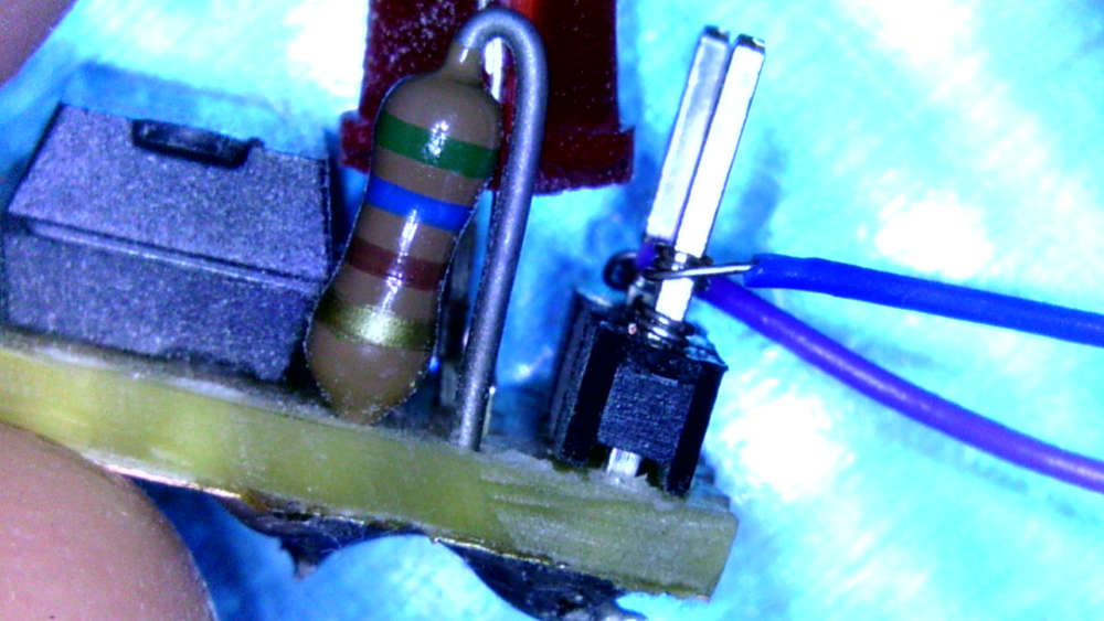
My actual project is a doorbell sensor with additional temperature and humidity sensors. Tried different ways to detect the ring:
- hall sensor (failed)
- microphone (FFT, ongoing research)
- optocoupler to detect the 12V AC -> favorite solution
As I was heavy prototyping, I tried wire wrapping and it is fun:
-
That looks awesome @alexsh1!
Nicely laid out and cleanly soldered. Was that with an iron or hot air (or both)? Nice clear silk too; I like the power and “signal” symbols. Did you ever try a FOTA update with it? Or a low power/speed profile?
I see you went a bit wider and longer than the standard Pro Mini, (I’m assuming) to get at all the pins and add the extra regulator, LEDs, etc.
I was constrained by needing something that fit the same footprint for existing boards I already had, e.g. other “motherboards” I’d made similar to @sundberg84’s excellent Easy/Newbie PCB or wanting pin-compatibility for stacking boards like the ATSHA+EEPROM+Radio+ICSP one below:
I tried routing with the chip at a 45 degree angle too but couldn’t get a DRC to pass with the pads so close to the PTHs. I may try again with shorter (custom) TQFP pads...
Re: 1284p’s downsides of cost and size.
I know. I ended up justifying it to myself this way:
We can all get cheap 328p Pro Minis from Ali for around $2. The vast majority of my Pro Mini projects are battery powered, so there’s some “labor cost” to disable the power LED and remove the regulator. But regardless, I certainly can’t make myself a low(er) power Pro Mini for $2 - the OSH Park PCB alone is probably close to that.
I think the cheapest I ever got 1284p chips for was around $2.50, again from Ali. My “Pro Mini XL” PCBs were around $1.70 from OSH Park, add a sprinkling of 0402s, etc. and we’re probably at around $5.
I couldn’t find any 1284p-based boards near that price. The closest I got was Kevin’s Mini Duino, which is another lovely looking board, but doesn’t fit my need for a Pro Mini-constrained size and pin-compatibility. Essentially, I was after something close to a drop-in replacement.
So, $2+ versus $5+ for all the benefits (at least as far as I was concerned) listed above? It became a bit of a no-brainer.
And on the low power front, I profiled the MySensors library sleep command on it at around 5uA on 4.5v @ 20MHz using an external full swing, around 4uA on 3v @ 8MHz and around 3uA on 1.8v @ 1MHz Internal RC Osc:
Those numbers are certainly good enough for all my current applications - no pun intended! ;)
But I would like to look at the 32-bit contenders as potential replacements.
I’ve seen nRF52s with 512K for around $2 on Ali, so maybe I’ll try my hand at a Pro Mini nRF52 or something similar eventually. The board above was a fun challenge, and afterall is what this is (mainly) about for me.
@acb Hot air has been used for soldering the board. I have not tried low power as I did not build this board for a battery sensor. My board has got two LEDs - power and another LED connected to D0 so clearly not very low power. I also have a 16Mhz firmware. I did not have any size limitation either. I have one particular node with a few sensors and with signing I cannot upload the sketch onto ATMEGA328P as it is marginally larger. Having said that I have not spent too much time optimising the sketch. I think that refactoring libraries, you are fine with ATMEGA328P in 98% of all MySensors applications.
BTW - this is not my project. I have followed it https://github.com/peekpt/mightyduinoRe cost. I stopped Ali shopping for ICs and other sensitive components some time ago after purchasing some fake ATMEGA328P and wasting so many hours trying to troubleshoot it. There is a post about it here on MySensors forum. Ever since I order all components on digi-key. 1284p is priced around $5 + 20% VAT. 328P is priced at $1.2 + VAT. However, I can also buy ATSAMD21 for $2.2 + VAT. Do you see my point? 1284p is extremely expensive and yet it is still 8 bit processor. That's why for me it was a one-off board.
Re sleeping
I am using TPL5110 which I built myself (similar to Adafruit one).
Check out sleeping current:
Sadly, I struggled to get some sensors to sleep properly - probably lack of my programming skills - and with a sleeping current being hundreds of uA, I had to resort to this trick. Most of the time, the node
sleepsis disconnected from power by TPL5110 then timer is up and it powers up, sends all sensors readings to the GW and then power gets disconnected to the node, only TPL5110 goes to nA sleep. Perfect!