What did you build today (Pictures) ?

-
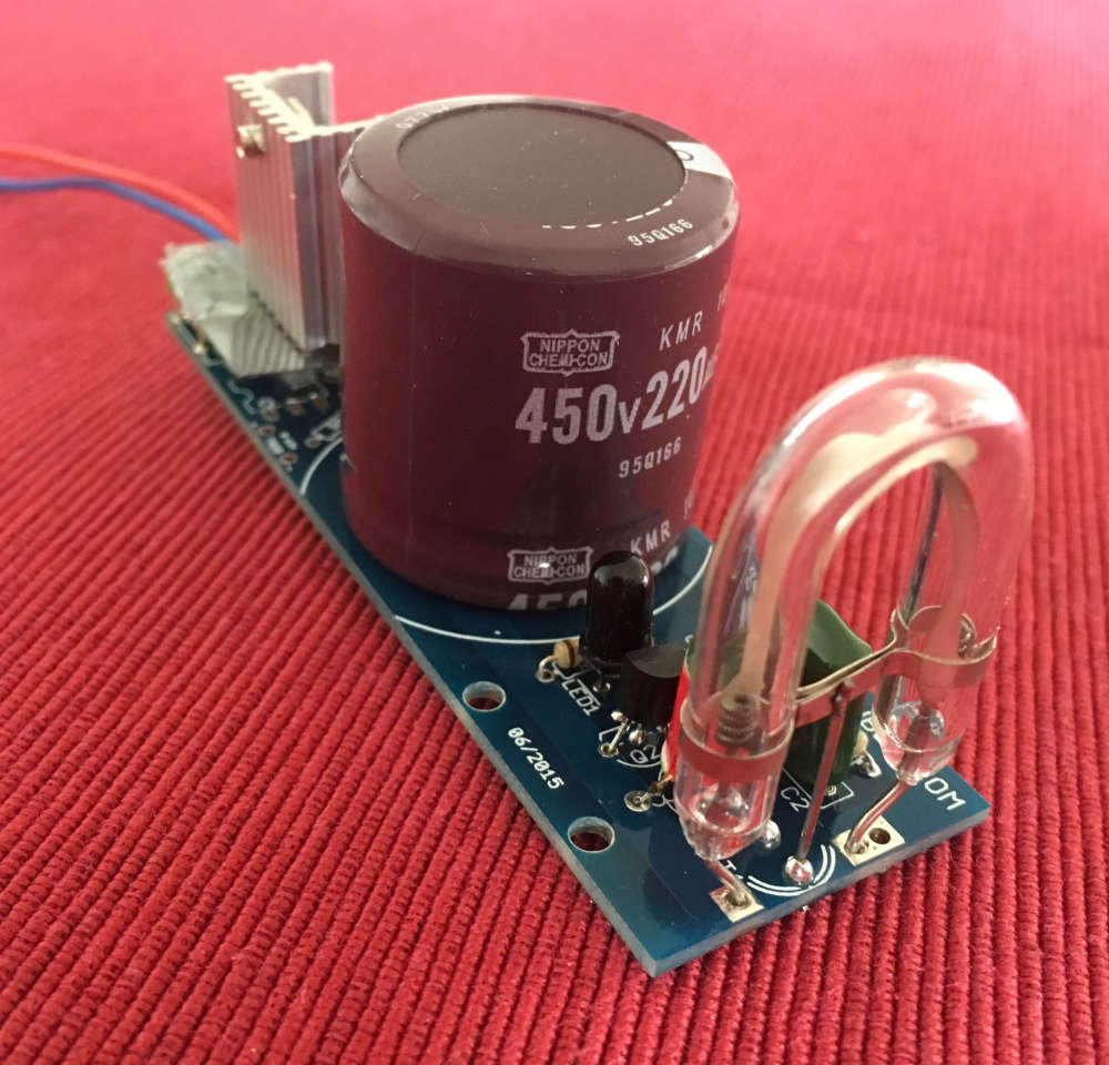
Building a (xenon) flash to notify alarms. Flashes every 5 seconds if activated.
-
-
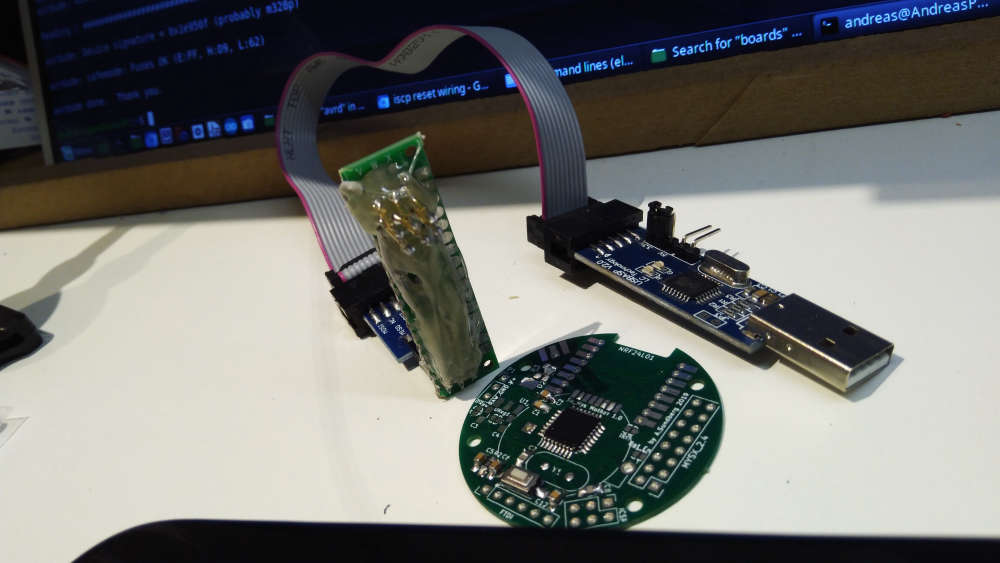
Today I made a iscp pogo pin adapter... Great for uploading bootloaders.
-
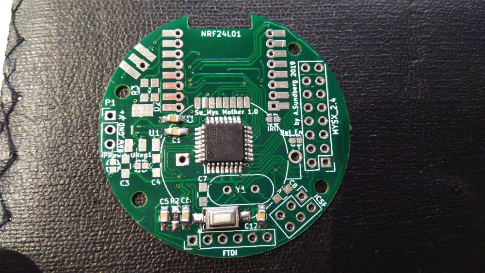
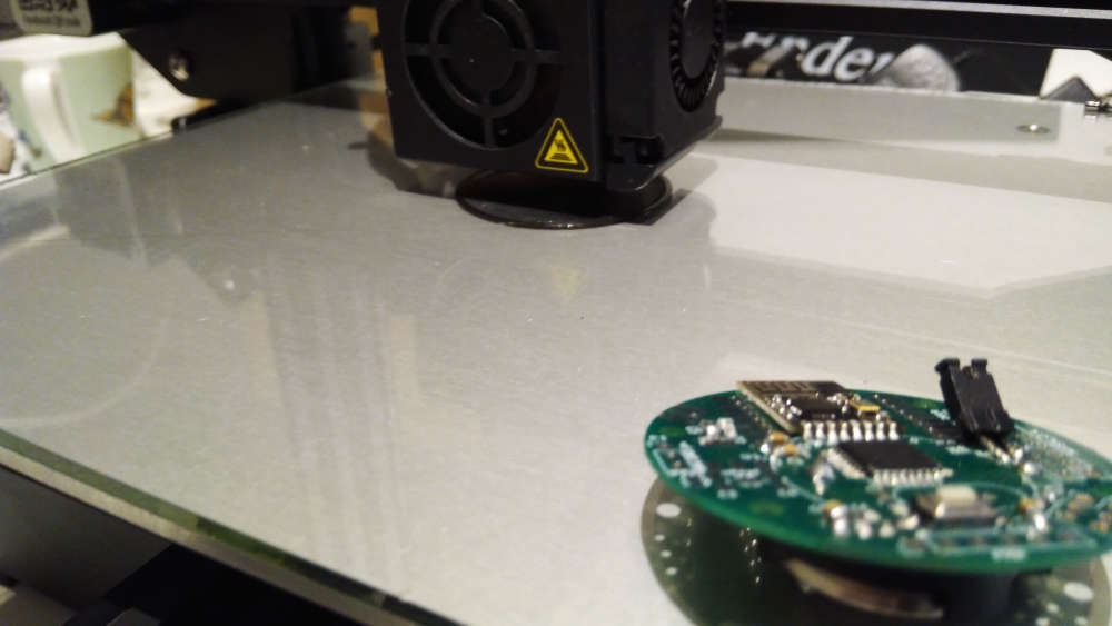
Almost finished one of my projects. The test sketch showed that HW works as it should. Now i need to make good software.
-
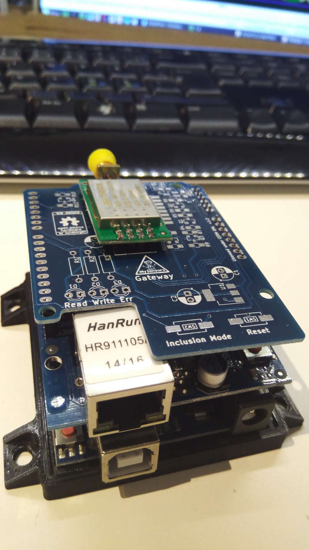
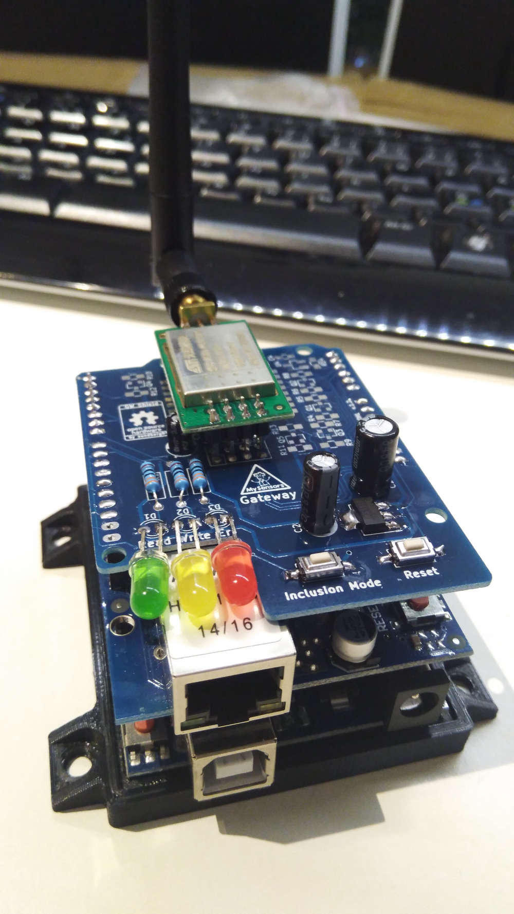
@sundberg84 that board looks nice and crisp 👍
-
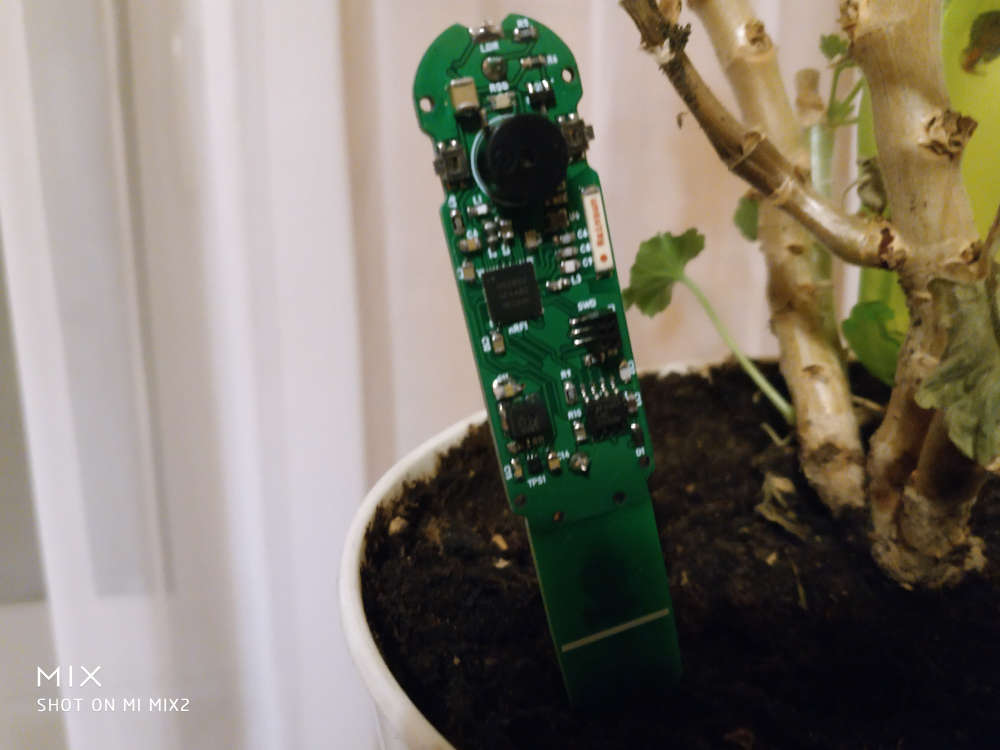
Birth of water leakage sensor:) on mysensors..
https://youtu.be/xsoeffaGAG0 -
After months of slow painstaking work (day job is somewhat busy, o and the kids ;) ) I finally completed my Domoticz server(case) with Dashticz as frontend.
The Endgame; when my new house is finished every room is monitored for motion, RH and Temperature using my MySensors PCB's. (Jung AS500 Node)
Everything is monitored using a raspberry with a MySensors serial gateway (NRF52) and an RFLink controller for my KAKU switches.
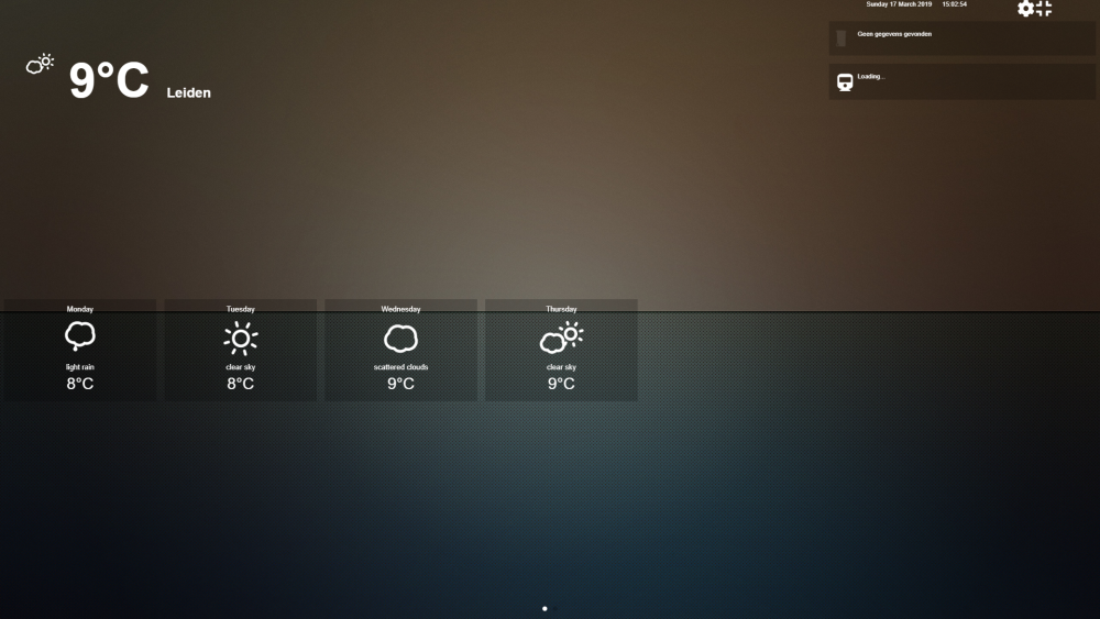
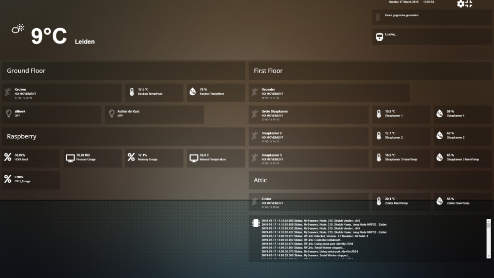
To make everything nice and shiny I use Dasticz to interface the data in a proper way using a tablet that somehow will be mounted on a wall or something.
So far the introduction;
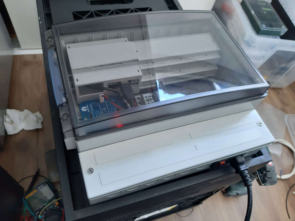
To put everything away nice and tidy I used a box to install everything using 2 pieces of din-rail.
It has a 230V inlet that is converted to 5V using an off the shelf (safety sake) MeanWell RS-15-5 converter. This powers everything using a couple of din-Rail terminals.
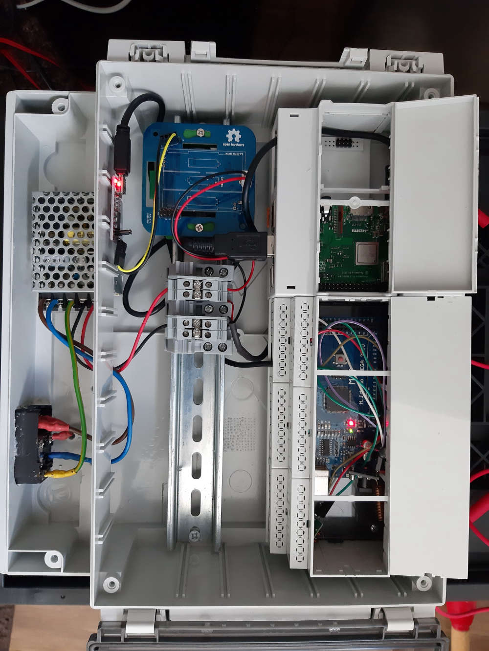
- Terminal => USB-micro => Raspberry
- Terminal => just a couple of wires => old nrf52 prototype => FTDI => Raspberry
- Raspberry => RF-link (ard. Mega +433mhz)
Since the Raspberry has Wifi no other cable then power is needed to operate
Second part: the 2 screenshots of dasthicsz.
The best part, it took some work, but the WAF incread big time, because everything looks clean :)
-
After months of slow painstaking work (day job is somewhat busy, o and the kids ;) ) I finally completed my Domoticz server(case) with Dashticz as frontend.
The Endgame; when my new house is finished every room is monitored for motion, RH and Temperature using my MySensors PCB's. (Jung AS500 Node)
Everything is monitored using a raspberry with a MySensors serial gateway (NRF52) and an RFLink controller for my KAKU switches.
To make everything nice and shiny I use Dasticz to interface the data in a proper way using a tablet that somehow will be mounted on a wall or something.
So far the introduction;
To put everything away nice and tidy I used a box to install everything using 2 pieces of din-rail.
It has a 230V inlet that is converted to 5V using an off the shelf (safety sake) MeanWell RS-15-5 converter. This powers everything using a couple of din-Rail terminals.
- Terminal => USB-micro => Raspberry
- Terminal => just a couple of wires => old nrf52 prototype => FTDI => Raspberry
- Raspberry => RF-link (ard. Mega +433mhz)
Since the Raspberry has Wifi no other cable then power is needed to operate
Second part: the 2 screenshots of dasthicsz.
The best part, it took some work, but the WAF incread big time, because everything looks clean :)
-
If someone would be interested:
Enclosure
Ard. Mega enclosure
Raspberry enclosureHad to do some modifications for the mega, but the cost of this enclosure was more than worth it.
Hmz.. normaly don't buy stuff at conrad but apparently they have good prices on cases... 😏
-
If someone would be interested:
Enclosure
Ard. Mega enclosure
Raspberry enclosureHad to do some modifications for the mega, but the cost of this enclosure was more than worth it.
Hmz.. normaly don't buy stuff at conrad but apparently they have good prices on cases... 😏
-
-
Testing a CCS811 CO2 sensor. It seems to use less power then the MH-Z14A I am using now. The CCS811 may even run on battery. I will compare measurements of these two sensors with a Netatmo sensor. The sensors have to burn in for two days bevore I start the comparison.
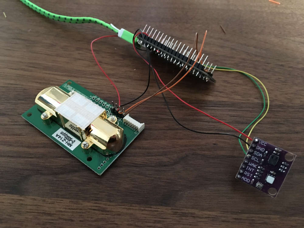
The CCS811 breakout board I use hast temp, hum and barometer sensors (and the CO2). -
Testing a CCS811 CO2 sensor. It seems to use less power then the MH-Z14A I am using now. The CCS811 may even run on battery. I will compare measurements of these two sensors with a Netatmo sensor. The sensors have to burn in for two days bevore I start the comparison.
The CCS811 breakout board I use hast temp, hum and barometer sensors (and the CO2).@fotofieber said in What did you build today (Pictures) ?:
Testing a CCS811 CO2 sensor.
Unfortunately this is not a CO2 sensor. It's only a VOC sensor giving an estimated eCO2 value. It's useful to tell you if your room needs ventilation, but not much more. And as even the VOC part is not calibrated it's only good for relative measurement.
AFAIK the only similar sensors which are calibrated and give absolute values are SGP30 and BME680.
If you want to measure CO2 you need a CO2 sensor and it's going to consume a lot of power, at least too much for a battery powered sensor.[edit] there's also the MiCS-VZ-89TE TVOC sensor, they claim to have a curve of eCO2 not too far from NDIR sensor in their datasheet. But that datasheet is strangely poor in details, they didn't even put any electrical characteristics...
https://sgx.cdistore.com/datasheets/sgx/MiCS-VZ-89TE_V1.0.pdf -
I don't think I ever managed to get it right the first revision.
Controller: Proxmox VM - Home Assistant
MySensors GW: Arduino Uno - W5100 Ethernet, Gw Shield Nrf24l01+ 2,4Ghz
MySensors GW: Arduino Uno - Gw Shield RFM69, 433mhz
RFLink GW - Arduino Mega + RFLink Shield, 433mhz -
I don't think I ever managed to get it right the first revision.
But it's something...
Controller: Proxmox VM - Home Assistant
MySensors GW: Arduino Uno - W5100 Ethernet, Gw Shield Nrf24l01+ 2,4Ghz
MySensors GW: Arduino Uno - Gw Shield RFM69, 433mhz
RFLink GW - Arduino Mega + RFLink Shield, 433mhz -
But it's something...
@sundberg84 you should print the board on paper, stick it on a piece cardboard and cut. Then check if size is good, you can even put the "big" components on it by sticking the pins through the cardboard to make sure you'll have enough space.
-
@sundberg84 you should print the board on paper, stick it on a piece cardboard and cut. Then check if size is good, you can even put the "big" components on it by sticking the pins through the cardboard to make sure you'll have enough space.
@nca78 great tip! But it's more common it's a schematic or footprint error. The outline "should" be the easy part even if I messed up.