CNC PCB milling
-
Given that the goal is to get 6mil isolatioin routing, what cutting depth should I set in flatcam? 0.05mm?
@neverdie I have been kind of following this topic, but don't have a CNC mill, but wouldn't the thickness of the copper clad on the board be your depth?
Vera Plus running UI7 with MySensors, Sonoffs and 1-Wire devices
Visit my website for more Bits, Bytes and Ramblings from me: http://dan.bemowski.info/ -
@neverdie I have been kind of following this topic, but don't have a CNC mill, but wouldn't the thickness of the copper clad on the board be your depth?
@dbemowsk said in CNC PCB milling:
@neverdie I have been kind of following this topic, but don't have a CNC mill, but wouldn't the thickness of the copper clad on the board be your depth?
Makes sense to me. Well, doing that it would be 0.01mm. But since this isn't a perfect process, it likely needs some added depth to guarantee it's removed. The effective tool width gets wider the deeper you cut, so in some sense I suppose there's that as an added constraint on how deep you can cut before it becomes more than 6 mil isolation. We could try to arrive at an answer analytically from first principles only, but I thought it might be easier to just ask what depth others who are doing this successfully are using.
-
@dbemowsk said in CNC PCB milling:
@neverdie I have been kind of following this topic, but don't have a CNC mill, but wouldn't the thickness of the copper clad on the board be your depth?
Makes sense to me. Well, doing that it would be 0.01mm. But since this isn't a perfect process, it likely needs some added depth to guarantee it's removed. The effective tool width gets wider the deeper you cut, so in some sense I suppose there's that as an added constraint on how deep you can cut before it becomes more than 6 mil isolation. We could try to arrive at an answer analytically from first principles only, but I thought it might be easier to just ask what depth others who are doing this successfully are using.
@neverdie you should use one depth, regardless of the trace width. for me 0.05mm worked, see my shared settings above. you should decide the isolation width, this is the main property for the given config, but you should stick for one milling depth only. if the requires isolation width is bigger than the tool width at a given depth, then it will use multiple rounds to reach the given width, but still, with one milling depth.
-
I'm stuck. I converted my gerber to gcode using flatcam, and imported it into Chilipeppr:
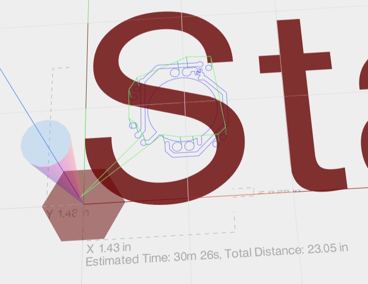
On the one hand, it seems to have gotten the dimensioning right, as indicated by the Y1.48in and X1.43in. However, the grid that it's showing is out of sync with that. Each square on the grid is 5mm. It's as though Chilipeppr thinks the entire design fits easily inside a 5mm square, and so when I attempt to do the autoleveling, it comes out completely wrong. -
I'm stuck. I converted my gerber to gcode using flatcam, and imported it into Chilipeppr:
On the one hand, it seems to have gotten the dimensioning right, as indicated by the Y1.48in and X1.43in. However, the grid that it's showing is out of sync with that. Each square on the grid is 5mm. It's as though Chilipeppr thinks the entire design fits easily inside a 5mm square, and so when I attempt to do the autoleveling, it comes out completely wrong.@neverdie said in CNC PCB milling:
I'm stuck. I converted my gerber to gcode using flatcam, and imported it into Chilipeppr:
On the one hand, it seems to have gotten the dimensioning right, as indicated by the Y1.48in and X1.43in. However, the grid that it's showing is out of sync with that. Each square on the grid is 5mm. It's as though Chilipeppr thinks the entire design fits easily inside a 5mm square, and so when I attempt to do the autoleveling, it comes out completely wrong.you can mark the zero point in the pcb designer tool before you export the gergbel, or in flatcam, during the post processing. if you do not define it, then maybe the given zero point could have some "offset" to the effective design. it is not problem, but it could make your life easier if your zero is e.g. at the pcb's corner.
if you don't want to update the files, then in chilipeppr you can update the probe area to not start from 0,0 but from a given offset. -
Thanks! I don't know why, but somehow that fixed the problem:
:) -
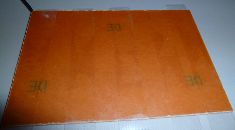
I found these copper clad boards that seem to be made out of bakelite (?) rather than fiberglass. So, hopefully not the same level of toxic dust concern as with FR4's.
I double sided taped the non-copper side:
and soldered a ground wire on the copper clad side:
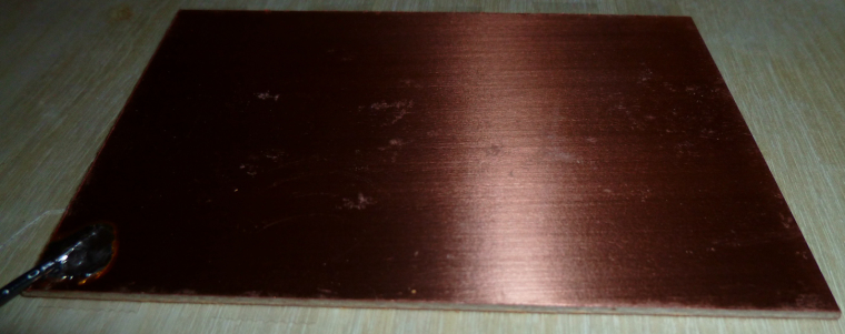
Now I'm ready for autoleveling and then my first PCB etch.
-
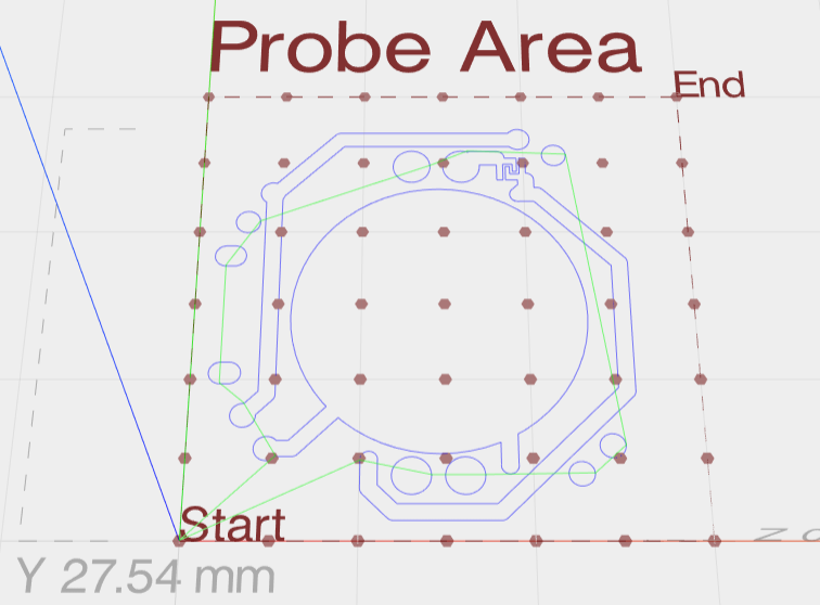
Here are the results of the autoleveling:
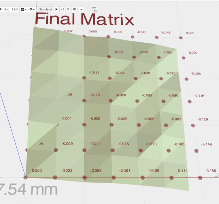
For some reason it's hard to read some of the numbers.@neverdie It looks like everything in the top right corner is above the level bed surface. which puts it above the grid that is shown. Looks like the bed is tilted.
Vera Plus running UI7 with MySensors, Sonoffs and 1-Wire devices
Visit my website for more Bits, Bytes and Ramblings from me: http://dan.bemowski.info/ -
@neverdie It looks like everything in the top right corner is above the level bed surface. which puts it above the grid that is shown. Looks like the bed is tilted.
-
LOL, except that unfortunately it did not:
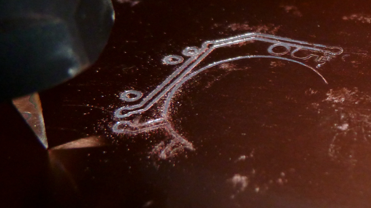
OK, my bad. I hadn't sent the auto-leveled g-code to the workspace (I had thought this would be done automatically, but no), so this picture shows what would happen without auto-leveling.
I've made the change and am now re-running the job with the auto-leveled g-code.
-
LOL, except that unfortunately it did not:
OK, my bad. I hadn't sent the auto-leveled g-code to the workspace (I had thought this would be done automatically, but no), so this picture shows what would happen without auto-leveling.
I've made the change and am now re-running the job with the auto-leveled g-code.
-
Judging from the looks of the photo directly above though, it looks like quite a bit of copper wasn't removed where it needed to be. I'm guessing I will need to:
- etch to a deeper depth; and/or,
- use a finer mesh for auto-leveling; and/or
- ???
-
Etch 0.1mm. The groove between tracks also helps with soldering. I currently use 0.1mm and even 0.15 when in a hurry.
-
So, I re-ran the job over the same area with the g-code modified by auto-leveling, and this time I got a better result:
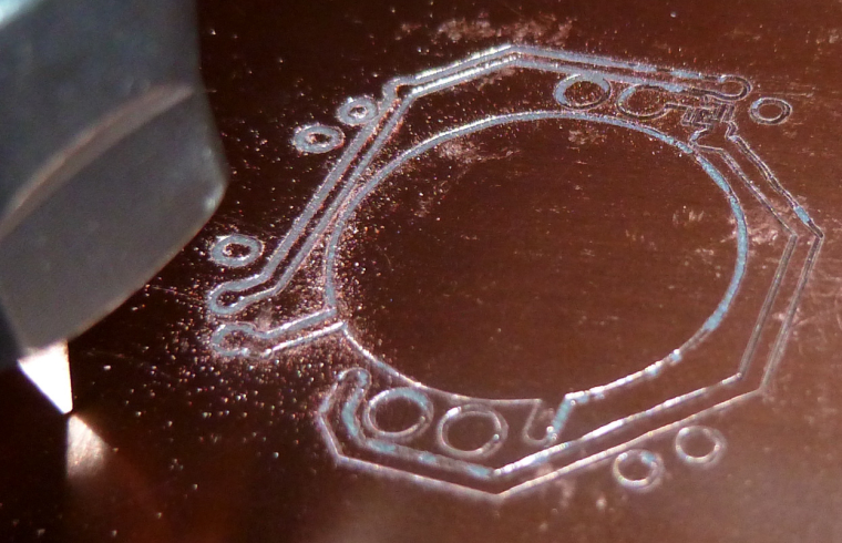
So, now I'll try it on a fresh area of the PCB, after doing a new auto-leveling.
-
@rmtucker Good catch! Here it is in contrast to a new one:
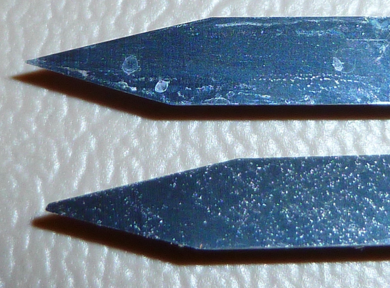
I'll replace it with the new one.
@neverdie
Just for future reference i would use a duff cutter for autolevelling then change to a good cutter to cut the job after resetting the z0.
It is so easy to smash the front of an engraving cutter when using this method for autolevelling as the machine takes a little time to stop after touching the pcb.
Just my advice anyway:relaxed: -
@neverdie
Just for future reference i would use a duff cutter for autolevelling then change to a good cutter to cut the job after resetting the z0.
It is so easy to smash the front of an engraving cutter when using this method for autolevelling as the machine takes a little time to stop after touching the pcb.
Just my advice anyway:relaxed:@rmtucker said in CNC PCB milling:
Just for future reference i would use a duff cutter for autolevelling then change to a good cutter to cut the job after resetting the z0.
What's a "duff cutter"? Did you mean "dull cutter"?