CNC PCB milling


  • Hero Member

    @rmtucker said in CNC PCB milling:

    Is it working correctly if you just issue a G0 x10 then x-10?

    No, it goes left in both instances.

    @rmtucker said in CNC PCB milling:

    did you switch to the jpadie workspace for v1.1?

    yes


  • @neverdie sorry, I'm abroad, with very limited availability, so cannot answer too quickly.

    based on the mentioned facts it seems to me, that the X axis direction pin is sticked to one position, maybe it has a solder bridge to another pin, or vcc / gnd directly.

    alt text


  • Hero Member

    @andrew said in CNC PCB milling:

    @neverdie sorry, I'm abroad, with very limited availability, so cannot answer too quickly.

    based on the mentioned facts it seems to me, that the X axis direction pin is sticked to one position, maybe it has a solder bridge to another pin, or vcc / gnd directly.

    alt text

    Thanks! You nailed it. It turns out the solder connection on the atmega328p pin corresponding to D5 just wasn't good enough. I resoldered it, and now the X-axis works in both directions. 🙂


  • Hero Member

    I'm receiving this error message now:
    0_1516478064369_crowded.png
    However, it's not obvious how to delete the files it's referring to. Anyone know how?


  • Mod

    @neverdie I haven't tried it, but if you are using Chrome you should be able to give ChiliPeppr unlimited storage through https://developer.chrome.com/extensions/declare_permissions


  • Hero Member

    Great news! Grbl1.1f makes all the difference. I tried milling at 6 mil separation using the upgraded grbl1.1f, and it works!
    0_1516480032752_eureka.jpg
    There's a huge difference between being able to evolve a single PCB design to perfect it rather than having to work on a "dumbed down" design (for a CNC or some other DIY etching process) before being able to get "the real deal" from a PCB fabricator. So, I'm very relieved that the first option now seems possible. 🙂


  • @neverdie I told you since the very beginning to make the firmware upgrade! 😉


  • @neverdie as I see from the picture, you can decrease the cutting depth. this could help you to soften the force against the carving bits and it could also help you to use faster feed rates without risking a missing step or bit damage.

    btw, what are your currently used parameters?

    also, for the best results please be sure, that when you set up the tool width in flatcam, then it is originated from the previously mentioned formula, which uses the carving bit properties (end with + angle) and the cutting depth.


  • Hero Member

    @andrew
    In this particular instance I had used a dull bit to do the autoleveling at 4mm and then switched to a Jack bit (nominal 0.1mm, 30 degrees) which I re-zeroed before starting the cutting.
    Cutting depth: 0.03
    Tool width: 0.12mm (just a guess as to the actual width)
    Feedrate:80mm

    It does seem that the actual cutting depth came out deeper than 0.03mm, so I'm not sure what's up with that. My guess is that the re-zeroing with the sharp bit came out wrong.


  • Hero Member

    @executivul said in CNC PCB milling:

    The metal piece is about 10cm long and it's left in place for the life of the wood board.

    Do you have a photo of that?

    Also, are you using double sided tape at all, or is this all that you're doing as far as holding the PCB flat against the sacrificial board?


  • Hero Member

    @andrew
    Trying to create a double sided PCB, but I am currently stuck on step 3:
    0_1516646766540_mirror.png
    I can see that it has created a mirror image which it displays, but I do not see a mirror image gerber object displayed in the project area. That's in contrast to step 4, where when I click "create alignment drill" it does create a drill file that I can see in the project area.

    Without access to a mirror image gerber object, there's nothing I can select to produce the gcode for the mirror image. So, I'm stuck on this step. How do I gain access to the mirror image gerber object? I've followed the given directions, but so far no joy.


  • Hero Member

    Apparently it doesn't produce a newly named gerber object. Instead, you just work with whatever it has in memory.


  • @neverdie

    1. I ise Scotch 665 double sided tape and lately I use a heavy item connected to the ground pin when probing. Put it on the pcb and you get the pcb face grounded. The probe pin clips to the bit. I tend to probe using the same bit used for engraving.
    2. You select the bottom layer in flatcam. I create a bounding box around it first. Then select the box, the x axis. A few alignment drill locations on one side of the flip line. Hit create aligment drills and hit mirror object which mirrors the already loaded bottom layer (GBL) object. If you watch closely you should see the tracks are mirrored. Then select the object and go on with creating iso geometry and cnc paths.

  • Hero Member

    @executivul said in CNC PCB milling:

    You select the bottom layer in flatcam. I create a bounding box around it first. Then select the box, the x axis. A few alignment drill locations on one side of the flip line. Hit create aligment drills and hit mirror object which mirrors the already loaded bottom layer (GBL) object. If you watch closely you should see the tracks are mirrored. Then select the object and go on with creating iso geometry and cnc paths.

    Yes, I think the flatcam's original instructions were faulty. It said to load both the top and bottom layer. Maybe that's fine for selecting pin alignment locations, but there should be only one layer displayed before the mirroring, or else it creates a mess.

    Also, I had thought it would create a new file for the mirrored gerber, but it doesn't. Instead, I just work with the mirrored gerber that's in memory to produce the gcode for the mirrored image. I guess that's good enough.


  • Hero Member

    I drilled the alignment holes with 0.8mm diameter. I'm using regular male header pins for the alignment, and having tried it, I think 0.8mm is really too tight. Not sure how @andrew is using 0.7mm. Different pins I guess? Anyhow, next time I'll try 0.9mm hole diameter.


  • Hero Member

    How do I mill a slot? Do I treat it the same as a regular hole, except use a routing bit rather than a drill bit when it comes time to cut the slot?


  • Hero Member

    @neverdie said in CNC PCB milling:

    How do I mill a slot? Do I treat it the same as a regular hole, except use a routing bit rather than a drill bit when it comes time to cut the slot?

    Couldn't find a good answer to this, so I'm going to approximate it by simply drilling a series of overlapping holes.

    It's needed for the micro-usb connector.


  • Hero Member

    I did the top layer, together with alignment holes, for a real FR4 PCB:
    0_1516726915446_alignment_holes.jpg
    As an experiment, I thought I would standardize on 0.9mm holes for the through-holes, via-holes, and alignment holes, so that there would be fewer tool changes. Looks like it will work, but, meh, I think I'll use smaller via holes in the future.

    Out of time for today, so I plan to etch the flip side tomorrow.


  • @neverdie 0.4-0.5mm for vias using 0.3mm silver plated "wrapping wire". 0.9 for TH and alignment holes.
    Tomorrow redo the alignment holes on the sacrificial layer so you get perfect alignment (if you don't have homing endstops, as I don't) and put the pins in and sick the pcb after that, be careful how you flip the board, I tend to use asymmetric alignment holes so I can only flip it one way (;


  • Hero Member

    Argh, it just occurred to me that I was premature in drilling the TH and via holes, because they may seriously interfere with the autoleveling when I etch the reverse side. This must be why @andrew etches the mirrored bottom side first, so that when it's flipped the top side can be etched and then drilled.


  • Hero Member

    Re-using the alignment holes already drilled, I flipped over the PCB and etched the mirrored bottom. It worked! Some of the traces are only as thick as a hair, but they all conduct and none are broken.

    I guess I'll have to flip it again in order to route the board outline. So, count that as yet another reason to start by etching the bottom first.
    0_1516739748977_bottom_mirror.jpg
    I had to autolevel at 6mm in order to dodge all the holes I had prematurely drilled, so perhaps that's why this particular etching came out so uneven.


  • @neverdie the order of the process should be the following:

    • drilling the alignment holes (through the PCB into the sacrificial layer)
    • fixing the pcb with the alignment pins/headers
    • isolation routing on the bottom layer
    • flipping the pcb
    • isolation routing on the top layer
    • drilling holes on the top layer
    • milling the pcb outline on the top layer

    as I see your results, you could use alignment holes closer to your actual design's border, but it should be definitely out of the pcb's edge + milling tool width area.

    the very thin traces are most probably caused by:

    • moving and not stable pcb
    • improperly calculated tool width
    • improper autoleveling on the given side


  • @neverdie said in CNC PCB milling:

    How do I mill a slot? Do I treat it the same as a regular hole, except use a routing bit rather than a drill bit when it comes time to cut the slot?

    you can mill holes, which are bigger than your drill bits, you can find a milling section in flat cam when you are working with the drill file.

    you can mill slots as well, for this the slot has to be designed properly in the PCB designer software. you have to draw closed shapes on e.g. the edge cuts layer, then basically you have to follow the same approach in flatcam that is used to create the edge milling cnc job, but instead of the edge lines, you have to select the slots.
    if you design it that way, then you can do both the slot and edge milling at once.


  • @neverdie said in CNC PCB milling:

    I drilled the alignment holes with 0.8mm diameter. I'm using regular male header pins for the alignment, and having tried it, I think 0.8mm is really too tight. Not sure how @andrew is using 0.7mm. Different pins I guess? Anyhow, next time I'll try 0.9mm hole diameter.

    maybe my pins also have different factors, but indeed, the given holes are pretty tight. this helps to prevent unnecessary pcb movements, which is very important if you work with 6mil traces/isolation, as a small unwanted movement could result in wasted pcb. if you work with bigger traces/clearings then it is not as important.

    I would recommend to stick to one size which is good for your selected pins and which does not let the pcb to move.


  • Hero Member

    Here's the final product:
    0_1516743797376_final.jpg
    Three of the vias are located under an SMD module, so I'll just have to try to minimize any solder bumps over them.


  • Hero Member

    Unfortunately, even a tiny solder bump prevents the module from being soldered. I would have to redesign this so that the vias are not under the module.


  • @NeverDie Just have to say, I have been following this thread for a while now and you have come a long way with this. Great job.


  • Hero Member

    Another good thing for people to know is that you can leave a single-sided blank PCB installed in the CNC and then, as the need arises, cut out additional modules from it:
    0_1516811876071_multiple.jpg

    For instance, this morning I cut this module carrier out of the above, already used, copper clad PCB:
    0_1516811948868_carrier.jpg

    So, for simple small things, it's a handy arrangement, and the incremental cost is negligible.


  • @neverdie Perhaps a clearer explanation ?


  • Hero Member

    One problem I've run into though is that the foil traces can sometimes lift up in the course of ordinary soldering. For instance, the traces connecting the second to the right pin on the Fanstel module seems to have utterly disappeared, leaving that pin unconnected:
    0_1516822629761_peel.jpg
    Maybe it's the quality of the blank PCB? I just don't know.


  • @neverdie It looks like you could potentially make those traces just a touch wider looking at the receiving end of the module. Woulld that be an option?


  • Hero Member

    @dbemowsk said in CNC PCB milling:

    Woulld that be an option?

    Maybe: I'll try a 10 degree bit and tighter autoleveling to see if that gives wider traces.


  • @neverdie i say that because in your previous pic of the board it looked like that trace was a bit narrow. Because of that it probably couldn't take the heat.


  • Hero Member

    It's funny, because I redid the soldering using an altogether new board, and it failed in exactly the same place:
    0_1516837780290_refail.jpg
    This time, though, you can actually see the copper trace has curled up away from the board.


  • @neverdie It is quite odd that that one did it and some of the others didn't on that side of the board. Looking at your previous image, the pads and traces on the side marked in green look noticeably larger than the ones marked in red. Look at the ones marked with the blue arrow. It looks like those should, or at least could be the same size. Your thru hole pads on the left for the breakout headers also look smaller than the ones on the right. Shouldn't the two sides be a mirror image of each other?
    0_1516838909597_613075bd-af72-4a92-8663-eb4012fe714a-image.png


  • Hero Member

    @dbemowsk It's because the left side of the board is higher than the righthand side, and apparently the autoleveling isn't working all that precisely.


  • @neverdie I can see that the left side looks like it cut deeper, which would cause that. I still think it is the thin traces though. Can you do any manual leveling of the bed? If so, I would attempt that. My Anet A8 3D printer, though not a CNC, is all manual leveling and I do have to check it from time to time.


  • Hero Member

    @dbemowsk said in CNC PCB milling:

    @neverdie I can see that the left side looks like it cut deeper, which would cause that. I still think it is the thin traces though. Can you do any manual leveling of the bed? If so, I would attempt that. My Anet A8 3D printer, though not a CNC, is all manual leveling and I do have to check it from time to time.

    I suppose I could shim under the sacrifice board with slips of paper to get the right height.

    I would have thought that the autoleveling would have accurately compensated though. Not sure why it isn't, especially if I'm autoleveling at 2mm spacing. Maybe this is an area where a future version of the GRBL driver will get it right.


  • @neverdie cnc milling auto leveling is not like 3d printing bed leveling.
    In 3d printing the firmware probes the bed, stores the values and automagically compensates at every move.
    In cnc milling the host control software asks the grbl to move and probe each point, then it modifies the gcode accordingly and sends that gcode to the controller which in turn just moves in the xyz coordinate system.
    Now, are you sure your gcode is updated to reflect the leveling?
    Normal flatcam gcode has a few Z-0.1 moves, the rest are only G1X...Y... (without Z) and autoleveled gcode has almost every move with z, like G1X...Y...Z.... Chilipeppr also adds some comments at the end of the lines like "new Z" or "Z mod".
    If you run the autoleveling probing but do not hit "send autoleveled gcode to workspace" in CP or "apply height map" in OpenCNCPilot the probing is useless.


  • @neverdie I just wasn't sure if your CNC had any way of manually leveling the bed. My 3D printer has screws in the 4 corners of the bed for me to manually level. I have been sticking to manual leveling on it because I have heard of people that have switched to auto-leveling that have had a number of problems. Maybe you need to switch to a different type of auto-leveling sensor.


  • @executivul Interesting. I did not know this. That is quite different.


  • @dbemowsk said in CNC PCB milling:

    @neverdie I just wasn't sure if your CNC had any way of manually leveling the bed. My 3D printer has screws in the 4 corners of the bed for me to manually level. I have been sticking to manual leveling on it because I have heard of people that have switched to auto-leveling that have had a number of problems. Maybe you need to switch to a different type of auto-leveling sensor.

    What firmware? BEST sensor ever = piezo sensor. I get 3 micron accuracy and repeatability. I use it on Marlin 1.1.8 with UBL on a corexy printer and also on a Smoothie delta.


  • @executivul I don't have a sensor yet. If I was going to switch to one I would have to flash a different firmware on my board. It is a newer version of Marlin.


  • @dbemowsk said in CNC PCB milling:

    @executivul I don't have a sensor yet. If I was going to switch to one I would have to flash a different firmware on my board. It is a newer version of Marlin.

    Marlin=Arduino (usually Mega2560). So UBL. What type of printer?


  • @executivul I do manual leveling and I rarely have to level the bed itself.


  • @neverdie for pcb milling a small height difference across the board's area could result in a big negative effect if autoleveling is not performed properly.
    I would double check your autoleveling process, on the other hand, you could also try to use bed flattening with a bigger endmill tool first, then place the pcb to the flattened area. this could help you to eliminate or decrease the cnc assembly or the sacrificial board caused roughness.

    for further details please see the following link:
    http://flatcam.org/manual/procedures.html#bed-flattening


  • @dbemowsk said in CNC PCB milling:

    @executivul I do manual leveling and I rarely have to level the bed itself.

    "If it works don't break it!"

    To end the offtopic, for anybody interested RepRap forum piezo discussion and https://www.precisionpiezo.co.uk/ the store of the guys who brought the piezo to the world, there are 1:1 clones on aliexpress, but the price is almost the same if you buy only the board and print your own holder and they provide warranty, fast shipping and are really great people so they deserve some support! (I'm not affiliated in any way to their store)

    LE. @NeverDie if you read this please look up 4-5 posts and tell me if your gcode has the autoleveling


  • Hero Member

    @executivul said in CNC PCB milling:

    if you read this please look up 4-5 posts and tell me if your gcode has the autoleveling

    yes. In Chilipeppr I send the autoleveling to the workspace, at which point it modifies the gcode.


  • Hero Member

    @andrew said in CNC PCB milling:

    @neverdie for pcb milling a small height difference across the board's area could result in a big negative effect if autoleveling is not performed properly.
    I would double check your autoleveling process, on the other hand, you could also try to use bed flattening with a bigger endmill tool first, then place the pcb to the flattened area. this could help you to eliminate or decrease the cnc assembly or the sacrificial board caused roughness.

    for further details please see the following link:
    http://flatcam.org/manual/procedures.html#bed-flattening

    What's the best type of sacrifice board to use if doing bed flattening? Regular wood, or should I stick with particle board or MDF?


  • Hero Member

    It seems the z-height only needs to be off by a small amount (say 0.02mm) to have a noticeably negative effect on the trace width.


  • @executivul said in CNC PCB milling:

    "If it works don't break it!"

    Amen to that


  • @neverdie said in CNC PCB milling:

    What's the best type of sacrifice board to use if doing bed flattening? Regular wood, or should I stick with particle board or MDF?

    I never had to try it, so I don't know. for me the regular wood seems to be logical...


  • @neverdie Sorry @andrew, wood is not a stable material, it is not inert and changes shape, it breathes if you will.

    Artificial materials such as particle board or MDF have a stable matrix, but of the two, MDF is the more uniform and least reactive, hence it's popularity for kitchen cupboards, loudspeaker cases, etc..
    It is easily machined, but is hard on the typical router bits, although nowhere near that of HDF.

    The bigger problem with mdf is the very fine dust produced when milling or cutting it with power tools, it gets everywhere, including your lungs, and can even get through vacuum cleaners without hepa filters....

    I would suggest either a thick MDF or layers glued together, cut the sides to requirements, lock it in place and set a 6 or 8mm router bit for MDF in a collet, and set it to work, ideally outside where you can hose it down after sweeping up and vacuuming.


  • Hero Member

    I think there may be some kind of coating that comes on these PCB's. Maybe it's to prevent corrosion of the copper? It seems to come off using IPA. Here one is before cleaning with IPA:
    alt text
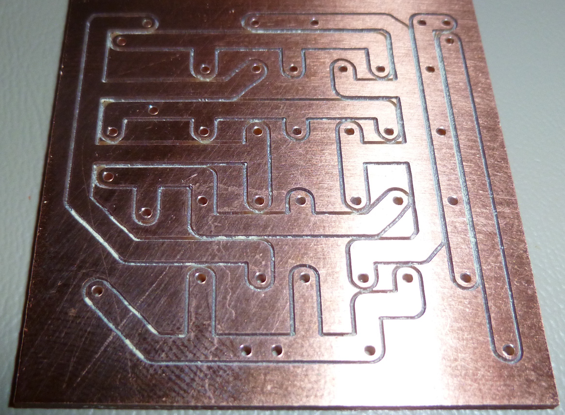
    And here is the same PCB after cleaning with IPA:
    0_1517268674877_cleaned.jpg
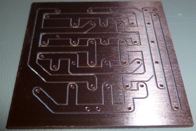
    Not sure whether it interferes with soldering. Anyone know? For now I'm cleaning it off.


  • @neverdie Looks like you have that board dialed in...


  • So a CNC question as I build my prototype machine. I have an arduino with CNC shield on order that should arrive tomorrow. My question is, does this allow for a display and keypad for local control or is everything just done through GRBL?
    https://www.amazon.com/SODIAL-Arduino-Compatible-DRV8825-StepStick/dp/B074FVTTR7/ref=sr_1_7?s=electronics&ie=UTF8&qid=1517499916&sr=1-7&keywords=arduino+uno+cnc


  • @dbemowsk

    All done via GCodeSender and similar i'm afraid... which is not a problem as far as i can see

    Your Arduino is fully populated with this board :

    • driving stepper drivers
    • end-stops
    • coolant (or wathever) enable
    • spindle control (speed and rotation) (V3 shield can do PWM control if your spindle driver can). Be aware that this board doesn't drive any kind of motor. Just sends signal
    • cloning axis of your choice
    • emergency stop, pause and resume
    • i might forget some details but i'm sure you get the point

    But it's a pretty cool board for veeeery reasonable price. I love it !


  • @ben999 Thanks can't wait to try it out.


  • @ben999 So reading through your specs, everything seems pretty straight forward. I get that the spindle motor will need it's own controller which can be driven by the CNC board. One thing I am confused on though, what is "cloning axis of your choice". I am new to CNC.


  • @dbemowsk this board can accept up to 4 stepper drivers

    your machine is probably a 3-axis CNC, so in most cases one stepper per axis could do the trick.

    BUT sometimes some CNC designs require a 2nd stepper for an axis (usually the x-axis). Then add a 4th driver and some jumpers and you're done. You end up with 2 steppers doing exactly the same job


  • @ben999 That makes sense. My 3D printer has 2 Z axis steppers.


  • So I received my CNC board today. After looking over the board, I see that it has 2 endstop points per axis. Logical assumption would be that there would be one on each end of travel of an axis. I was a bit confused because my 3D printer only has 1 per axis. Do I need to use both for each axis when running GRBL?


  • So today I decided to do a little bit of testing with the CNC shield and my Y axis drive. To start off, one of the issues I have is that I do not know the specs of the motor that I have. Here is a pic:
    0_1517727837555_dd30a30a-2162-4fab-b31b-82b58830f05f-image.png
    Did quite a bit of searching over the past week to try and find any information, and I can't seem to find what I need. I decided to do some tests anyway. I was able to get GRBL loaded on to the UNO board fine and connect to it through PUTTY. I then installed just the Y axis driver and connected a 12 volt power supply for starters. I was able to get the Y axis screw turning by sending some Y axis commands such as "Y20" or "Y-20". When I ran it initially I didn't have the Y axis platter mount secured to anything, so that would just spin with the screw. The problem I have is that if I hold the platter mount giving the screw even the slightest bit of resistance, the motor will spin for half a second and then start making a whining/buzzing noise and will just vibrate a bit. Once the motor starts to slow down while stopping, the screw will stop whining and spin slightly at the end of the stop. I then thought that it might be that the voltage was too low as I had read on some forums about some Epson steppers being higher voltage steppers, so I connected a 30 volt supply. Running the same test gave me the same results. Does anyone have a clue as to why this would happen? Basically the motor doesn't have any torque.


  • @dbemowsk current gets you torque, voltage gets you speed. What driver do you use? See the current setting for the driver you use, how/what voltage you measure to determine the current and the formula that links the two.

    When I want to set the sweetspot (assuming driver and stepper are somewhat matched) I start low and increase the current little by little until the stepper gets warm after a few minutes. Warm, not hot! But again, the driver and stepper must match, I wouldn't try that with a Pololu A4988 and a Nema 34 stepper 😂


  • @executivul said in CNC PCB milling:

    What driver do you use?

    DRV8825


  • @dbemowsk well then check the current set by measuring Vref, plenty of tutorials on the web. If it's lower than 500mA try bumping it up little by little. Also try reducing the microsteps to 16 or 8 by removing jumpers.


  • Hero Member

    The adjustment screw on the stepper module allows you to set max allowable current.

    Also, in software, you could try setting a lower max acceleration parameter (as discussed earlier in this thread) and lower max velocity parameters, in case either or both are a factor.

    You're brave to be attempting this with unknown equipment. If there are multiple factors... it's trickier to troubleshoot with no working baseline to start with.


  • Hero Member

    I've changed my modus operandi so that now I use the largest pad and trace sizes that I can get away with. That way, if they get whittled down during the milling, I still hopefully have enough left. 🙂
    Example:
    0_1517759010931_ra-01_layout.jpg


  • Hero Member

    That way, I can also cut deeper and wider, which helps with soldering.
    0_1517761319040_fatpads.png


  • So good news. I was able to get the motor turning with some torque. Initially the board was set at full step resolution (no jumpers on M0, M1 or M2). I thought I'd try it at it's lowest microstep resolution which is 1/32, and the motor ran good. I checked the max current and it was set quite high at 2.035 x 2 = 4.07 A. Running some Y axis moves got the motor a bit warm, but I don't think I ran it long enough to do much damage. I now have the current down to 0.254 x 2 = 0.508 A and it seems to be running quiet and good. With it being at 1/32 microstepping it took a lot of revolutions to move the platter mount any distance, so I bumped it to 1/16 microstepping. This is mainly due to the 4.8:1 gear ratio that I have. I think this should give me some pretty good precision on the Y axis at least. Haven't built the X or Z yet, but that is next.


  • @neverdie said in CNC PCB milling:

    You're brave to be attempting this with unknown equipment.

    I'm not too worried. Worst case I may have to get some other steppers. Being that this motor is salvaged, it's not like it costed me anything.


  • Hero Member

    Here's my first attempt at copper removal between the traces/pads:
    0_1517774707509_copper_recmove.jpg
    I used a 2mm endmill to do the work pretty fast. It actually came out pretty good, but the remaining un-removed copper is not what I wanted. I guess it's inevitable unless I use a supper narrow end-mill, or probably a carving bit. But that will take a lot longer.

    i.e. some kind of hybrid approach would be best, I should think. Is there some way to do the detailed cleanup with a small bit, and then switch to the large diameter bit for the fast cleanup where precision isn't needed?


  • @neverdie Looks like you could raise your end mill a bit (no pun intended). Shouldn't it be the same depth as your other bit?


  • Hero Member

    @dbemowsk said in CNC PCB milling:

    @neverdie Looks like you could raise your end mill a bit (no pun intended). Shouldn't it be the same depth as your other bit?

    In theory, I suppose maybe so. However, the trouble is I can't preserve and then re-apply the same auto-leveling results. And, after the initial isolation milling, I can't do another to support setting the copper removal depth, because the touchpoints might hit the already removed material, which would seriously skew the results. So, I just set it deep enough to cover the possibilities, and that's why it's deeper.

    If anyone has a better solution to that, I'm all ears.


  • Hero Member

    I did get better removal using a carving bit:
    0_1517780462492_copper_recmove3.jpg


  • @neverdie My apologies for near hijacking your thread. I am going to create a new one so I don't mess yours up.


  • Hero Member

    @dbemowsk No worries. Not really my thread. It's @andrew 's. I'm just a disciple. 🙂


  • Hero Member

    Answering my own earlier questin, I forgot to remove the PCB coating using IPA before soldering. I think it probably did make the soldering come out a bit funky looking:
    0_1517787555954_soldered_ra01.jpg
    Next time I'll remove it first.

    Appearances aside, though, it should still work.


  • Hero Member

    I made the breakout board a bit smaller, and then, since the proof of the pudding is in the taste, I connected it to a pro mini and ran it. Voilà! It works like a charm. 🙂
    0_1517863497322_proMini_LoRa.jpg


  • Hero Member

    @andrew What is the widest diameter end-mill bit that this CNC machine can accept and handle? I'm thinking in terms of the mill leveling discussed earlier, and going wide to speed up the process.


  • @neverdie Pardon my interruption, but I seem to recall my mentioning this near the start of this CNC adventure, and that there was a collet available for that device to accept 8mm standard wood routing bits...
    I realise that US traditionally holds to 1/4 and 1/2 inch shafts, but the bigger the size the greater the mass to spin up and motor requirements... Pretty sure you would still be able to find 8mm bits...


  • Hero Member

    @zboblamont I have an ER11 though, so doesn't that preclude using a bigger collet?


  • @neverdie Google it... The ER11 8mm collet indeed exists, although the ads on Ali seem to sell it partnered with a shaft extension.
    I'm not familiar with your machine, but well acquainted with wood routers...
    Old size bit shafts were 1/4" and 1/2" and probably are predominant in the US, metric were 6mm and 8mm etc... Have only used 8mm personally, but with 1500-2000w routers they make short work of mdf.
    For the job you have in mind a 1/4" is probably meaty enough if your motor has the power to handle the cutting rate...

    There is no reason to go big on the bit diameter, a 1/4" would be plenty strong enough to do what you require and should be readily available stateside... If you have the collet of course...


  • Hero Member

    @zboblamont So, indeed, it looks like there is quite a range of collet sizes available for ER11: https://www.maritool.com/Collets-ER-Collets-ER11-Collets/c21_56_60/index.html

    It's harder to judge what end-mill diameter the motor can handle though. The motor looks very light duty.


  • Hero Member


  • Hero Member

    @neverdie said in CNC PCB milling:

    try the Shurtape GG-200 that was recommended in the Hackaday article.

    I finally received it, and I tried it yesterday. Definitely has more grip than the regular double sided Scotch tape.


  • @neverdie If you go 6mm or 1/4 inch only to flatten the bed, you might be better off just selecting the collet after buying a plain router bit locally, probably neither will be used for much if anything until you need to replace the bed.... They are pretty cheap usually and ideal for mdf, just keep the cutting rate cautious with the light drive motor, and beware of the dust, it goes everywhere, and you can't spray it as water affects the mdf...
    A 1/4" face cutter would put less load on your motor than a 1/2", just take it easy on the milling rate....


  • Hero Member

    I'm not sure how to analyze it a priori. If I have to run it at a much lower feedrate to compensate for a light duty motor, then the supposed speed benefits of a larger end-mill might not materialize.


  • @neverdie said in CNC PCB milling:

    a priori

    ? You mean as earlier, sorry, I didn't use Latin after 60BC, it rather went out of fashion don't you know.... 😉
    The power you require to bring the mass up to speed is one thing, the speed of approach and the area to be cut is the greater puzzle I suggest. The bit will not snap for sure, your motor might object if you take big bites though...
    If you rip the surface in a 0.5mm top slice and listen to the motor you will get a good idea of how it reacts, then either increase the approach speed or the depth I would suggest.. You are using the device outside it's parameters, better to be cautious, the bits are a lot tougher than the motor...


  • Hero Member

    I ordered the collets and end-mills that I referenced above, so after they arrive I'll post an update as to how it went.

    Meanwhile, now that my CNC is in the garage, it's hard to know when it has finished running. I'm thinking of making a node to monitor it and then sent me a wireless alert when it finishes. So, how best to know when it has finished? I'm presently toying with the idea of monitoring its current consumption, on the theory that if no significant current is flowing, then it is done. However, maybe someone here knows of a better way?


  • @neverdie I find it hard to believe you would just walk away from it with no curiosity or desire for direct observation. Have you considered using the highly technical door to access and use eyes to see and ears to listen ? You are breaking new ground here, or mdf actually, where is that American spirit? Did Galoka think the Ulus were too ugly to save?....
    Beyond the giggles, I suggest a strategically placed vacuum cleaner intake as close as you can get taped down and just watch what happens, you are in a better position to cut power than 20m away diverted by Youtube....


  • Hero Member

    @zboblamont
    Watching it do an auto-level on 300 points is pretty boring.... I have better things to do than watch paint dry.


  • @neverdie Hey, your choice, your motor.....
    Watching paint dry is most under-rated really, except when you are on the other end of the brush...


  • Mod

    @neverdie why not put a webcam/ipcam at it, like many people do with a 3d printer?
    Will show you when it's finished and when something goes wrong.


  • Hero Member

    @zboblamont I think maybe you're misunderstanding. I would watch it do the bed-level (well, at the beginning anyway), to monitor drain on the motor. However, with all the auto-leveling and etching and milling and drilling I just let it run and come back when it's finished. That's really where I want to go with this in the end anyway. As far as protecting the motor, there should be (but maybe isn't?) something to shut it down if the current jumps above a certain limit. I should think that would be all the protection that's needed. So, maybe that's yet another reason to task an arduino with monitoring the current flow. One reason would be to alert me when the present job is done. The other reason would be to shut it all down if the current got too high (indicating a failure situation of some kind).

    In fact, the beauty of having it in the garage is that it can run in the background without being noticed. If I were to run it in the house, the noise is rather overwhelming, and it would be hard to ignore it.


  • Hero Member

    @yveaux said in CNC PCB milling:

    @neverdie why not put a webcam/ipcam at it, like many people do with a 3d printer?
    Will show you when it's finished and when something goes wrong.

    I just don't see the allure in that. It requires my polling it, rather than being interrupt driven. To me it's like putting a webcam on your dryer to observe when it's done. I mean, yes, it is faster than walking over to it, but it just seems far from optimal.


  • Hero Member

    So, anyhow, maybe another way to check for job completion would be to monitor the DATA+ line from the USB cable feeding the WoodPecker controller. I'm guessing that if it shows no activity, then the job is done.


  • Is there something like, or does octoprint work with CNC machines? That might be an option if it does. Octoprint can monitor with an attached USB webcam


  • Hero Member

    Yesterday I was doing copper removal with a 2mm end-mill, and several times when plunging it brought the motor to a complete stop. The motor recovered and continued in the x-y dimension at the new z.

    So, obviously, the z-feedrate was too high. Is there a feedrate specific to the z-axis, or is it just the same as the general feedrate used by the x-y? I know there are velocity and acceleration parameters that can be different for x,y, and z. Do I control it using that instead of the seemingly general purpose "feedrate"?

    Also, not sure why I experienced the problem this time and not previous times, as I was running the same g-code as before. Perhaps the end-mill acquired too much plastic gunk clinging to it? What's the best way to clean that stuff off?


  • Hero Member

    @neverdie said in CNC PCB milling:

    Is there a feedrate specific to the z-axis, or is it just the same as the general feedrate used by the x-y?

    I ran some tests and proved that the general feedrate does apply to the z-axis. However, at the moment, the rest of the answer remains unknown to me.


Log in to reply
 

Suggested Topics

  • 4
  • 2
  • 5
  • 3
  • 1
  • 14

23
Online

11.2k
Users

11.1k
Topics

112.5k
Posts