CNC PCB milling
-
One more thing worth mentioning: This guy has, I think, a correct insight into why auto-leveling may not work as well in the real world as it theoretically should:
Blank PCB material is not as rigid as it appears, depending on its size and how it was stored (not to mention how you mount it) there will be some bowing which results in a curved surface under your engraver.
Unfortunately, the probing process doesn't put enough pressure on the board to push it down while the actual engraving process will. This means you will get shallow cuts even with an autolevelling process.
The trick is to ensure that the probe pushes the board down to it's fully flat level before measuring the height at that point. My solution was to put a small ball on the spindle that is 2mm lower than the probe tip - as the probe moves downwards the ball pushes the PCB to the underlying bed and compresses before the probe makes contact. This gives you a far more accurate depth reading.
https://blog.thegaragelab.com/seven-pcb-milling-tips/His solution looks like this:

which looks as though it could be improved upon. -
Recent strategy was to do multiple overlapping passes with a narrow diameter bit to get lots of isolation. It nominallly worked, but it consumed a lot of machine time. So, now testing a new strategy, which is to first do one bulk isolation with a wide bit and then do one final pass with a narrow bit to clean out whatever copper remains near the traces. Though it does require a tool change, in theory it should be faster.
-
I have found a YouTube channel that has a few video's about using the 3018 CNC for PCB milling.
They winked a bit at the Wegstr promotional video.
But they seem to get good quality. They also have better video's explaining the steps.
CNC PCB - high quality with the budget 3018 CNC – 05:20
— DIY TECH BROS -
Can anyone here explain the appeal of Mach3 in the year 2020? The premise seems to be: don't use stepper driver hardware (e.g. Trinamics) and don't use a motion controller, but instead do all the stepper motor control directly from a PC by bit-banging pins on a parallel port in real-time!? How is that a good idea, and why is it advantageous? I understand how maybe back in the day that was perhaps the most affordable way to do it, but these days? I just don't get it.
-
Can anyone here explain the appeal of Mach3 in the year 2020? The premise seems to be: don't use stepper driver hardware (e.g. Trinamics) and don't use a motion controller, but instead do all the stepper motor control directly from a PC by bit-banging pins on a parallel port in real-time!? How is that a good idea, and why is it advantageous? I understand how maybe back in the day that was perhaps the most affordable way to do it, but these days? I just don't get it.
@NeverDie Just get any Atmega328 board (Uno, Nano) and flash grbl 1.1f and wire it to whatever drivers you have (now I'm using hybrid closed loop servos, but I've used TB6560 in the past).
I use OpenCNCPilot, it has autolevel, and a lot of other useful functions: simplify, arc to lines, split long lines, etc. I mainly use it for splitting long lines, as a long move doesn't account for the board topography (local highs and lows), by splitting the line accordingly to the detail needed (5mm for dip, 2-3mm for smaller smd boards) I get a much better engraving. Also the autoloevel grid size and step setting is very simple. -
@NeverDie Just get any Atmega328 board (Uno, Nano) and flash grbl 1.1f and wire it to whatever drivers you have (now I'm using hybrid closed loop servos, but I've used TB6560 in the past).
I use OpenCNCPilot, it has autolevel, and a lot of other useful functions: simplify, arc to lines, split long lines, etc. I mainly use it for splitting long lines, as a long move doesn't account for the board topography (local highs and lows), by splitting the line accordingly to the detail needed (5mm for dip, 2-3mm for smaller smd boards) I get a much better engraving. Also the autoloevel grid size and step setting is very simple.Hi executivul! Great to hear from you again.
@executivul said in CNC PCB milling:
@NeverDie Just get any Atmega328 board (Uno, Nano) and flash grbl 1.1f and wire it to whatever drivers you have (now I'm using hybrid closed loop servos, but I've used TB6560 in the past).
On Aliexpress I notice there are these drivers (one per axis) that it sounds as though you are using. Some of them (usually blue) are self-described as "Hybrid", whereas others (often Green or some other color) are self-described as "closed loop." I haven't tried either one, but I get the impression that the "Hybrid" drivers function closed loop as well, and it sounds as though that is what you are doing. If that is the case, what, if any, functional difference is there between the self-described "hybrid" drivers and the self-described "closed-loop" drivers? I assume you know what I'm referring to, but if not, let me know and I'll post pictures and links in order to clarify.
-
By the way, good news! Just yesterday I think I've identified the very same spring-loaded bit used very successfully by both Bantam Tools and Wegstr for removing DIY solder mask over solder pads. :grin: Details here: https://www.cnczone.com/forums/pcb-milling/408516-best-material-spoilboard-beneath-pcb-etching-best.html#post2395490
For anyone not familiar with this process, here is a demo video:
How To Make a PCB Solder Mask with the Bantam Tools PCB Milling Machine – 02:53
— Bantam ToolsI'll be giving it a try once my rig is upgraded and re-tuned, because obviously the z-axis height needs to be controlled very precisely for it to work without etching off the same copper pads that I'll be trying to re-expose from under the solder mask. I suppose using 2oz copper clad might also be worth it for the wee bit of added headroom. If push comes shove, I've read that even thicker copper clad PCB is available, though off-hand I have no idea where would be a good place to buy it. From what I've read the thicker cladding is most often found in PCB's made for military applications.
Edit: Gave a quick cursory look, and both 3oz and 4oz copper clad PCB is not hard to find. Not saying it will be needed, but nice to know in case it is.
-
Time to upgrade the motion controller. The woodpecker is hopeless because it takes 12v-36v input voltage and downconverts it to 12v:

This means you can't actually drive your stepper stick at more than 12v, even though the A4988 can use up to 36v and the DRV8825 up to 45v. The TMC5160 allows up to 60v. I'm guessing the grbl board designers did this to avoid any possibility of going over the allowed voltage, which would mean fewer warrantee returns. All well and good for them, but if I'm not mistaken, it deprives the user of snappier accelerations.So, I ordered just a primitive arduino shield, and hopefully it is lacking this "feature":

The board markings do indicate the same 12-36v range, though, but I'm guessing that's there purely either as a cautionary warning for A4988 users or because that's the highest voltage that the capacitors are rated for. Given the cramped board, perhaps trace widths are a factor as well.The mechaduino driver can handle voltages up to 40v, but the mechaduino board itself was designed with 36v capacitors. The MKS-servo42a has a 30v maximum according to the design they borrowed from.
All this does make me interested in trying a TMC5160 at 60v just to see how much snappier it might be.
Unfortunately, the uStepper (http://ustepper.com/product_sheet_revB.pdf), despite using the TMC5160, doesn't take advantage of the 60v possibility. It recommends 24v input voltage, with a 30v maximum.
Good grief! Why, oh why, did they do that? Was it just to save a few pennies on component cost? Will I have to design my own board if I want high performance?
I was originally hoping for this to be a drop-in upgrade. Maybe it still is, but I'm starting to have doubts about just how much of a performance upgrade I can expect from it.
-
Reporting back: I received the el cheapo GRBL boards (above). The good news is that they don't have a buck converter getting in the way, the way the woodpecker does. The bad news is that the caps are rated at only 40v. So, I may replae them with ones rated for higher voltage. Also, there's a mysterious glass fuse soldered in the midst of it all. Not sure at what current it's rated to blow but, meh, probably high enough if the designer did his homework.
So, overall, I expect this will be an improvement over woodpecker for running GRBL at higher voltage. :-)
-
@NeverDie judging from the images, this looks like a diode instead of a fuse.
Anyway, keep up the good reading, I'm loving your posts :+1:@Yveaux said in CNC PCB milling:
@NeverDie judging from the images, this looks like a diode instead of a fuse.
Not a bad guess based on the image you were working from, but if so it's a diode with the word "FUSE" written under it:

:wink:Anyway, keep up the good reading, I'm loving your posts :+1:
Thanks for the encouragement! :-)
-
The nice thing about this particular board is that there's an easy way to levitate a fan over it to cool down the stepsticks:

-
@Yveaux said in CNC PCB milling:
@NeverDie judging from the images, this looks like a diode instead of a fuse.
Not a bad guess based on the image you were working from, but if so it's a diode with the word "FUSE" written under it:
:wink:Anyway, keep up the good reading, I'm loving your posts :+1:
Thanks for the encouragement! :-)
-
@NeverDie said in CNC PCB milling:
a diode with the word "FUSE" written under it
Got me there, but it seems to be a fuse with orientation :thinking_face:
We'll never know unless you put a multimeter on it :wink:@Yveaux said in CNC PCB milling:
@NeverDie said in CNC PCB milling:
a diode with the word "FUSE" written under it
Got me there, but it seems to be a fuse with orientation :thinking_face:
We'll never know unless you put a multimeter on it :wink:OK, I just now probed it, and it conducts with the same 0.12 ohm resistance in both directions. So, it's not a diode. Here's a closeup photo that I took for you:
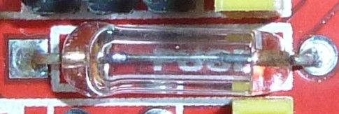
I'm going to deem it a fuse unless you have a different theory or can recognize it as something else.Anyhow, changing topics, the good news is that the electrolytic capacitors have a higher voltage rating than what I had reported earlier. They are 100uF capacitors, and upon closer inspection it says that they are rated at 50v, not 40v as I had earlier thought. That's good news, because it means they should be able to handle the 45v maximum that DRV8825 stepper drivers can tolerate. :-)
-
@Yveaux said in CNC PCB milling:
@NeverDie said in CNC PCB milling:
a diode with the word "FUSE" written under it
Got me there, but it seems to be a fuse with orientation :thinking_face:
We'll never know unless you put a multimeter on it :wink:OK, I just now probed it, and it conducts with the same 0.12 ohm resistance in both directions. So, it's not a diode. Here's a closeup photo that I took for you:
I'm going to deem it a fuse unless you have a different theory or can recognize it as something else.Anyhow, changing topics, the good news is that the electrolytic capacitors have a higher voltage rating than what I had reported earlier. They are 100uF capacitors, and upon closer inspection it says that they are rated at 50v, not 40v as I had earlier thought. That's good news, because it means they should be able to handle the 45v maximum that DRV8825 stepper drivers can tolerate. :-)
@NeverDie Did you check out the assembly instructions? There they use a fuse with a rather high current in this place :rolling_on_the_floor_laughing: :rolling_on_the_floor_laughing: :rolling_on_the_floor_laughing:
The explanation why it is polarized is because in fact, it used to be a diode in older revisions, check out Step 7 here. -
-
@NeverDie Did you check out the assembly instructions? There they use a fuse with a rather high current in this place :rolling_on_the_floor_laughing: :rolling_on_the_floor_laughing: :rolling_on_the_floor_laughing:
The explanation why it is polarized is because in fact, it used to be a diode in older revisions, check out Step 7 here.@eiten said in CNC PCB milling:
The explanation why it is polarized is because in fact, it used to be a diode in older revisions, check out Step 7 here.
Yeah, let's look at that:
D1(Diode) was intended to prevent users from damaging the board by accidentally reversing the polarity on the high voltage line. Unfortunately this feature was abandoned because I could not find a big enough Diode that would handle 6 amps at a time and still fit on the board. The work around for this is to solder in a jumper wire (Yellow Wire).
LOL. This excuse just doesn't ring true. I mean, by version 3 he still couldn't manage to find space on the board for a suitable diode? Nevermind that he could have used an alternative for reverse polarity protection, like a mosfet, which also wouldn't have incurred as large a voltage drop.
Well, speaking of diodes, I don't see any TVS or zener diodes on this board for protection against back EMF. I guess that's just assumed to be handled by the driver modules?
-
@eiten said in CNC PCB milling:
The explanation why it is polarized is because in fact, it used to be a diode in older revisions, check out Step 7 here.
Yeah, let's look at that:
D1(Diode) was intended to prevent users from damaging the board by accidentally reversing the polarity on the high voltage line. Unfortunately this feature was abandoned because I could not find a big enough Diode that would handle 6 amps at a time and still fit on the board. The work around for this is to solder in a jumper wire (Yellow Wire).
LOL. This excuse just doesn't ring true. I mean, by version 3 he still couldn't manage to find space on the board for a suitable diode? Nevermind that he could have used an alternative for reverse polarity protection, like a mosfet, which also wouldn't have incurred as large a voltage drop.
Well, speaking of diodes, I don't see any TVS or zener diodes on this board for protection against back EMF. I guess that's just assumed to be handled by the driver modules?
@NeverDie and for reverse polarity protection, you could just use a FET, a resistor and a Zener (only necessary if reversed voltage is breaking the FET, which is cheaper if you have some amps and has loooots of less power dissipation:
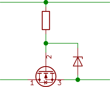
I use this on all my PCBs with removable batterys. Luxury upgrade: a reverse voltage indicator:
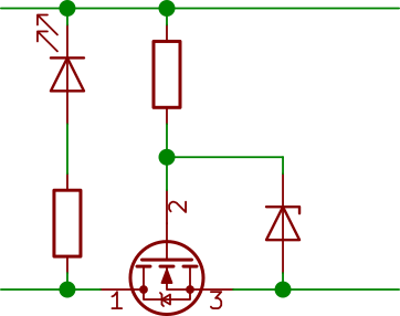
Add a Zener parallel to the LED if you have a wide expectet input voltage range. -
@eiten said in CNC PCB milling:
The explanation why it is polarized is because in fact, it used to be a diode in older revisions, check out Step 7 here.
Yeah, let's look at that:
D1(Diode) was intended to prevent users from damaging the board by accidentally reversing the polarity on the high voltage line. Unfortunately this feature was abandoned because I could not find a big enough Diode that would handle 6 amps at a time and still fit on the board. The work around for this is to solder in a jumper wire (Yellow Wire).
LOL. This excuse just doesn't ring true. I mean, by version 3 he still couldn't manage to find space on the board for a suitable diode? Nevermind that he could have used an alternative for reverse polarity protection, like a mosfet, which also wouldn't have incurred as large a voltage drop.
Well, speaking of diodes, I don't see any TVS or zener diodes on this board for protection against back EMF. I guess that's just assumed to be handled by the driver modules?
@NeverDie said in CNC PCB milling:
speaking of diodes, I don't see any TVS or zener diodes on this board for protection against back EMF. I guess that's just assumed to be handled by the driver modules?
Well, according to Pololu, capacitors are to be used for that instead:
Warning: This carrier board uses low-ESR ceramic capacitors, which makes it susceptible to destructive LC voltage spikes, especially when using power leads longer than a few inches. Under the right conditions, these spikes can exceed the 35 V maximum voltage rating for the A4988 and permanently damage the board, even when the motor supply voltage is as low as 12 V. One way to protect the driver from such spikes is to put a large (at least 47 µF) electrolytic capacitor across motor power (VMOT) and ground somewhere close to the board.
Actually, this might be better anyway, since different driver boards may have different maximum voltages, and using a capacitor would adapt to that.
So, it remains to be seen whether the given 50v rating on a 100uF capacitor is enough if I were to raise the supply voltage to 45v to drive DRV8825's at their maximum voltage. The board design may not have accounted for that, since it sets an arbitrary limit of 36v for input voltage, as stated on the silk screen. I guess the way to test it experimentally would be to start at 35v and then creep up the voltage while monitoring an in-use capacitor in situ on an oscilloscope while driving the stepper at maximum acceleration and then suddenly stopping. I presume that would be the worst case scenario. However, I'm not sure what the gcode for that would be. Anyone know? If not, I may just have to settle for jogging the stepper around and take measurements based on that instead.