CNC PCB milling
-
Time to upgrade the motion controller. The woodpecker is hopeless because it takes 12v-36v input voltage and downconverts it to 12v:

This means you can't actually drive your stepper stick at more than 12v, even though the A4988 can use up to 36v and the DRV8825 up to 45v. The TMC5160 allows up to 60v. I'm guessing the grbl board designers did this to avoid any possibility of going over the allowed voltage, which would mean fewer warrantee returns. All well and good for them, but if I'm not mistaken, it deprives the user of snappier accelerations.So, I ordered just a primitive arduino shield, and hopefully it is lacking this "feature":

The board markings do indicate the same 12-36v range, though, but I'm guessing that's there purely either as a cautionary warning for A4988 users or because that's the highest voltage that the capacitors are rated for. Given the cramped board, perhaps trace widths are a factor as well.The mechaduino driver can handle voltages up to 40v, but the mechaduino board itself was designed with 36v capacitors. The MKS-servo42a has a 30v maximum according to the design they borrowed from.
All this does make me interested in trying a TMC5160 at 60v just to see how much snappier it might be.
Unfortunately, the uStepper (http://ustepper.com/product_sheet_revB.pdf), despite using the TMC5160, doesn't take advantage of the 60v possibility. It recommends 24v input voltage, with a 30v maximum.
Good grief! Why, oh why, did they do that? Was it just to save a few pennies on component cost? Will I have to design my own board if I want high performance?
I was originally hoping for this to be a drop-in upgrade. Maybe it still is, but I'm starting to have doubts about just how much of a performance upgrade I can expect from it.
-
Reporting back: I received the el cheapo GRBL boards (above). The good news is that they don't have a buck converter getting in the way, the way the woodpecker does. The bad news is that the caps are rated at only 40v. So, I may replae them with ones rated for higher voltage. Also, there's a mysterious glass fuse soldered in the midst of it all. Not sure at what current it's rated to blow but, meh, probably high enough if the designer did his homework.
So, overall, I expect this will be an improvement over woodpecker for running GRBL at higher voltage. :-)
-
@NeverDie judging from the images, this looks like a diode instead of a fuse.
Anyway, keep up the good reading, I'm loving your posts :+1:@Yveaux said in CNC PCB milling:
@NeverDie judging from the images, this looks like a diode instead of a fuse.
Not a bad guess based on the image you were working from, but if so it's a diode with the word "FUSE" written under it:

:wink:Anyway, keep up the good reading, I'm loving your posts :+1:
Thanks for the encouragement! :-)
-
The nice thing about this particular board is that there's an easy way to levitate a fan over it to cool down the stepsticks:

-
@Yveaux said in CNC PCB milling:
@NeverDie judging from the images, this looks like a diode instead of a fuse.
Not a bad guess based on the image you were working from, but if so it's a diode with the word "FUSE" written under it:
:wink:Anyway, keep up the good reading, I'm loving your posts :+1:
Thanks for the encouragement! :-)
-
@NeverDie said in CNC PCB milling:
a diode with the word "FUSE" written under it
Got me there, but it seems to be a fuse with orientation :thinking_face:
We'll never know unless you put a multimeter on it :wink:@Yveaux said in CNC PCB milling:
@NeverDie said in CNC PCB milling:
a diode with the word "FUSE" written under it
Got me there, but it seems to be a fuse with orientation :thinking_face:
We'll never know unless you put a multimeter on it :wink:OK, I just now probed it, and it conducts with the same 0.12 ohm resistance in both directions. So, it's not a diode. Here's a closeup photo that I took for you:
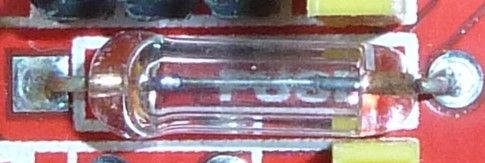
I'm going to deem it a fuse unless you have a different theory or can recognize it as something else.Anyhow, changing topics, the good news is that the electrolytic capacitors have a higher voltage rating than what I had reported earlier. They are 100uF capacitors, and upon closer inspection it says that they are rated at 50v, not 40v as I had earlier thought. That's good news, because it means they should be able to handle the 45v maximum that DRV8825 stepper drivers can tolerate. :-)
-
@Yveaux said in CNC PCB milling:
@NeverDie said in CNC PCB milling:
a diode with the word "FUSE" written under it
Got me there, but it seems to be a fuse with orientation :thinking_face:
We'll never know unless you put a multimeter on it :wink:OK, I just now probed it, and it conducts with the same 0.12 ohm resistance in both directions. So, it's not a diode. Here's a closeup photo that I took for you:
I'm going to deem it a fuse unless you have a different theory or can recognize it as something else.Anyhow, changing topics, the good news is that the electrolytic capacitors have a higher voltage rating than what I had reported earlier. They are 100uF capacitors, and upon closer inspection it says that they are rated at 50v, not 40v as I had earlier thought. That's good news, because it means they should be able to handle the 45v maximum that DRV8825 stepper drivers can tolerate. :-)
@NeverDie Did you check out the assembly instructions? There they use a fuse with a rather high current in this place :rolling_on_the_floor_laughing: :rolling_on_the_floor_laughing: :rolling_on_the_floor_laughing:
The explanation why it is polarized is because in fact, it used to be a diode in older revisions, check out Step 7 here. -
-
@NeverDie Did you check out the assembly instructions? There they use a fuse with a rather high current in this place :rolling_on_the_floor_laughing: :rolling_on_the_floor_laughing: :rolling_on_the_floor_laughing:
The explanation why it is polarized is because in fact, it used to be a diode in older revisions, check out Step 7 here.@eiten said in CNC PCB milling:
The explanation why it is polarized is because in fact, it used to be a diode in older revisions, check out Step 7 here.
Yeah, let's look at that:
D1(Diode) was intended to prevent users from damaging the board by accidentally reversing the polarity on the high voltage line. Unfortunately this feature was abandoned because I could not find a big enough Diode that would handle 6 amps at a time and still fit on the board. The work around for this is to solder in a jumper wire (Yellow Wire).
LOL. This excuse just doesn't ring true. I mean, by version 3 he still couldn't manage to find space on the board for a suitable diode? Nevermind that he could have used an alternative for reverse polarity protection, like a mosfet, which also wouldn't have incurred as large a voltage drop.
Well, speaking of diodes, I don't see any TVS or zener diodes on this board for protection against back EMF. I guess that's just assumed to be handled by the driver modules?
-
@eiten said in CNC PCB milling:
The explanation why it is polarized is because in fact, it used to be a diode in older revisions, check out Step 7 here.
Yeah, let's look at that:
D1(Diode) was intended to prevent users from damaging the board by accidentally reversing the polarity on the high voltage line. Unfortunately this feature was abandoned because I could not find a big enough Diode that would handle 6 amps at a time and still fit on the board. The work around for this is to solder in a jumper wire (Yellow Wire).
LOL. This excuse just doesn't ring true. I mean, by version 3 he still couldn't manage to find space on the board for a suitable diode? Nevermind that he could have used an alternative for reverse polarity protection, like a mosfet, which also wouldn't have incurred as large a voltage drop.
Well, speaking of diodes, I don't see any TVS or zener diodes on this board for protection against back EMF. I guess that's just assumed to be handled by the driver modules?
@NeverDie and for reverse polarity protection, you could just use a FET, a resistor and a Zener (only necessary if reversed voltage is breaking the FET, which is cheaper if you have some amps and has loooots of less power dissipation:
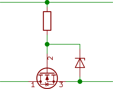
I use this on all my PCBs with removable batterys. Luxury upgrade: a reverse voltage indicator:
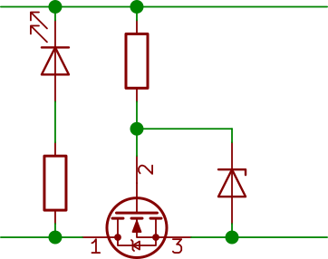
Add a Zener parallel to the LED if you have a wide expectet input voltage range. -
@eiten said in CNC PCB milling:
The explanation why it is polarized is because in fact, it used to be a diode in older revisions, check out Step 7 here.
Yeah, let's look at that:
D1(Diode) was intended to prevent users from damaging the board by accidentally reversing the polarity on the high voltage line. Unfortunately this feature was abandoned because I could not find a big enough Diode that would handle 6 amps at a time and still fit on the board. The work around for this is to solder in a jumper wire (Yellow Wire).
LOL. This excuse just doesn't ring true. I mean, by version 3 he still couldn't manage to find space on the board for a suitable diode? Nevermind that he could have used an alternative for reverse polarity protection, like a mosfet, which also wouldn't have incurred as large a voltage drop.
Well, speaking of diodes, I don't see any TVS or zener diodes on this board for protection against back EMF. I guess that's just assumed to be handled by the driver modules?
@NeverDie said in CNC PCB milling:
speaking of diodes, I don't see any TVS or zener diodes on this board for protection against back EMF. I guess that's just assumed to be handled by the driver modules?
Well, according to Pololu, capacitors are to be used for that instead:
Warning: This carrier board uses low-ESR ceramic capacitors, which makes it susceptible to destructive LC voltage spikes, especially when using power leads longer than a few inches. Under the right conditions, these spikes can exceed the 35 V maximum voltage rating for the A4988 and permanently damage the board, even when the motor supply voltage is as low as 12 V. One way to protect the driver from such spikes is to put a large (at least 47 µF) electrolytic capacitor across motor power (VMOT) and ground somewhere close to the board.
Actually, this might be better anyway, since different driver boards may have different maximum voltages, and using a capacitor would adapt to that.
So, it remains to be seen whether the given 50v rating on a 100uF capacitor is enough if I were to raise the supply voltage to 45v to drive DRV8825's at their maximum voltage. The board design may not have accounted for that, since it sets an arbitrary limit of 36v for input voltage, as stated on the silk screen. I guess the way to test it experimentally would be to start at 35v and then creep up the voltage while monitoring an in-use capacitor in situ on an oscilloscope while driving the stepper at maximum acceleration and then suddenly stopping. I presume that would be the worst case scenario. However, I'm not sure what the gcode for that would be. Anyone know? If not, I may just have to settle for jogging the stepper around and take measurements based on that instead.
-
-
Anyhow, I ordered one of these tramming tools:
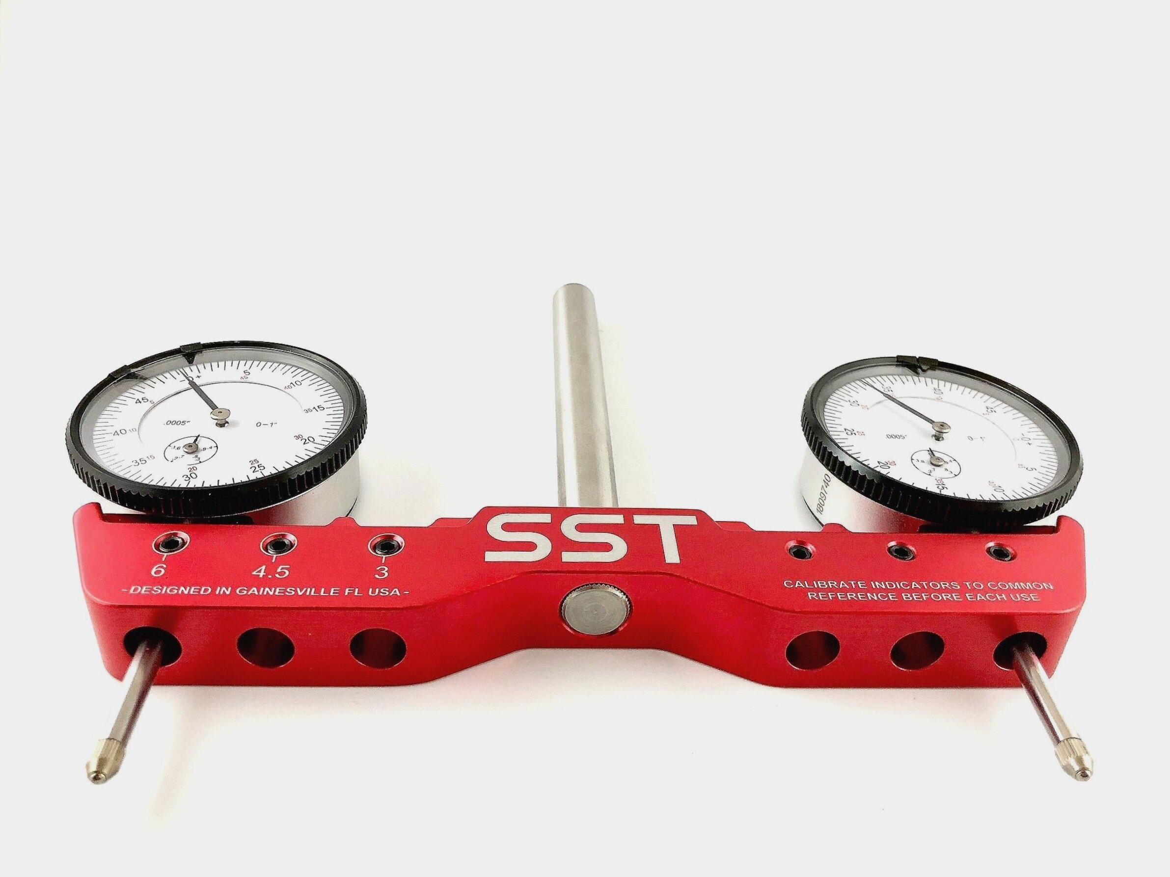
so that I can do accurate repeatability tests on the z-axis, and that is because I will need to be deadnuts accurate if I am to selectively CNC mill the solder mask off from a PCB without destroying the underlying solder pads. i'm not sure I will have enough headroom on the z-axis to fit this tool into place--or use it for that matter--so I'll just have to see how that goes after it arrives. A lot may depend on how far I can plunge the dial indicators before they bottom out. -
By the way, I just now found a online outfit which will cnc laser cut steel up to 1" thick. Their name? Yeah, you guessed it: oshcut.
https://www.oshcut.com
A really interesting option for my next CNC after this one would be to design the whole thing in CAD and then have it laser cut out of stainless steel. As compared to Chinese aluminum extrusion CNC's, I can see this as having two advantages: 1. Steel is far stronger and more rigid than aluminum, and so it would be lightyears ahead in that regard, and 2. I'm guessing the parts would be far more dimensionally accurate than whatever gets banged out in China for shipment through Aliexpress. In the past what has held me back from building a CNC from scratch is the need to precisely drill all the holes with just exactlly right amount of spacing, parallelism, and perpendicularity. However, with access to cnc laser cut steel, I presumably get all the dimensional accuracy I would need at no extra cost.Fanciful? I think not. A kid in Poland did his own CNC design and had the steel parts lasercut in Poland. In just the past few days he finished putting it together, and it looks like a pretty reasonable design using both ballscrews and steel rail guides, held together will steel gussets that he designed himself in CAD:
https://www.youtube.com/watch?v=5jFCecZdbGsI'd say it looks better than most of what China is selling. In fact, he's giving his design files away for free, so if you wanted to I suppose you could have the exact same parts lasercut and shipped to your door. Pretty cool! :sunglasses: This looks like it could (finally!) be the start of truly open source CNC designs, as compared to the past where you more or less had to buy all the custom cut parts from somebody else, who, of course, was selling them at a mark-up relative to their own costs.
-
Anyhow, I ordered one of these tramming tools:
so that I can do accurate repeatability tests on the z-axis, and that is because I will need to be deadnuts accurate if I am to selectively CNC mill the solder mask off from a PCB without destroying the underlying solder pads. i'm not sure I will have enough headroom on the z-axis to fit this tool into place--or use it for that matter--so I'll just have to see how that goes after it arrives. A lot may depend on how far I can plunge the dial indicators before they bottom out.@NeverDie said in CNC PCB milling:
so that I can do accurate repeatability tests on the z-axis, and that is because I will need to be deadnuts accurate if I am to selectively CNC mill the solder mask off from a PCB without destroying the underlying solder pads. i'm not sure I will have enough headroom on the z-axis to fit this tool into place--or use it for that matter--so I'll just have to see how that goes after it arrives. A lot may depend on how far I can plunge the dial indicators before they bottom out.
Dial based tramming depends on table being flat, otherwise result is so so.
Eventually I've used 3d printed bar with holes for 1/4" stub bit to mount into collet
and 1/8" on other side for a scrap v-bit with probe clip attached. It allows to tram spindle in X and Y directions compared to dial gauge ( only X direction, due to not enough clerance under X axis frame)Yields about the same result as dial method against uneven table almost for free. Putting MDF spoil board, and levelling, helps a bit but then one gets "waves" if the spindle is not perpendicular to the table and given that MDF is not conductive, I couldn't use probe again to re-measure.
That was solved by using steel gauge plate (I used 10x15x500mm) to serve as other end of the probe. It takes only few facing iterations to level bed with facing bit, in each direction (X and Y). Also gauge plate across whole table takes care of evening 'waves' and it's still cheaper than a good dial gauge (not speaking about dedicated tramming contraption above). Caveat is that it's much slower than using
dial gauge due to slow probing but in my case it was more repeatable so it's hard to tell which method was slower in the end.With bCNC it's possible to use gcode macro to do tedious work of probing, so one needs only to manually rotate probe 180° and press a button to see which direction axis is skewed.
-
Have any of you tried to make a vacuum table?
When it comes to the solder mask. Based on video I say this is done easier bij using UV exposure only. If you are using UV paint anyway, then you might as well print the design on a transparent sheet.
-
@NeverDie said in CNC PCB milling:
so that I can do accurate repeatability tests on the z-axis, and that is because I will need to be deadnuts accurate if I am to selectively CNC mill the solder mask off from a PCB without destroying the underlying solder pads. i'm not sure I will have enough headroom on the z-axis to fit this tool into place--or use it for that matter--so I'll just have to see how that goes after it arrives. A lot may depend on how far I can plunge the dial indicators before they bottom out.
Dial based tramming depends on table being flat, otherwise result is so so.
Eventually I've used 3d printed bar with holes for 1/4" stub bit to mount into collet
and 1/8" on other side for a scrap v-bit with probe clip attached. It allows to tram spindle in X and Y directions compared to dial gauge ( only X direction, due to not enough clerance under X axis frame)Yields about the same result as dial method against uneven table almost for free. Putting MDF spoil board, and levelling, helps a bit but then one gets "waves" if the spindle is not perpendicular to the table and given that MDF is not conductive, I couldn't use probe again to re-measure.
That was solved by using steel gauge plate (I used 10x15x500mm) to serve as other end of the probe. It takes only few facing iterations to level bed with facing bit, in each direction (X and Y). Also gauge plate across whole table takes care of evening 'waves' and it's still cheaper than a good dial gauge (not speaking about dedicated tramming contraption above). Caveat is that it's much slower than using
dial gauge due to slow probing but in my case it was more repeatable so it's hard to tell which method was slower in the end.With bCNC it's possible to use gcode macro to do tedious work of probing, so one needs only to manually rotate probe 180° and press a button to see which direction axis is skewed.
@niallain said in CNC PCB milling:
Eventually I've used 3d printed bar with holes for 1/4" stub bit to mount into collet
and 1/8" on other side for a scrap v-bit with probe clip attached. It allows to tram spindle in X and Y directions compared to dial gauge ( only X direction, due to not enough clerance under X axis frame)Do you have any pictures you can post?
