CNC PCB milling
-
@NeverDie said in CNC PCB milling:
a diode with the word "FUSE" written under it
Got me there, but it seems to be a fuse with orientation :thinking_face:
We'll never know unless you put a multimeter on it :wink:@Yveaux said in CNC PCB milling:
@NeverDie said in CNC PCB milling:
a diode with the word "FUSE" written under it
Got me there, but it seems to be a fuse with orientation :thinking_face:
We'll never know unless you put a multimeter on it :wink:OK, I just now probed it, and it conducts with the same 0.12 ohm resistance in both directions. So, it's not a diode. Here's a closeup photo that I took for you:
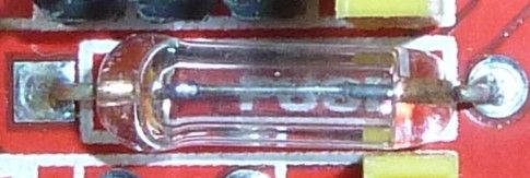
I'm going to deem it a fuse unless you have a different theory or can recognize it as something else.Anyhow, changing topics, the good news is that the electrolytic capacitors have a higher voltage rating than what I had reported earlier. They are 100uF capacitors, and upon closer inspection it says that they are rated at 50v, not 40v as I had earlier thought. That's good news, because it means they should be able to handle the 45v maximum that DRV8825 stepper drivers can tolerate. :-)
-
@Yveaux said in CNC PCB milling:
@NeverDie said in CNC PCB milling:
a diode with the word "FUSE" written under it
Got me there, but it seems to be a fuse with orientation :thinking_face:
We'll never know unless you put a multimeter on it :wink:OK, I just now probed it, and it conducts with the same 0.12 ohm resistance in both directions. So, it's not a diode. Here's a closeup photo that I took for you:
I'm going to deem it a fuse unless you have a different theory or can recognize it as something else.Anyhow, changing topics, the good news is that the electrolytic capacitors have a higher voltage rating than what I had reported earlier. They are 100uF capacitors, and upon closer inspection it says that they are rated at 50v, not 40v as I had earlier thought. That's good news, because it means they should be able to handle the 45v maximum that DRV8825 stepper drivers can tolerate. :-)
@NeverDie Did you check out the assembly instructions? There they use a fuse with a rather high current in this place :rolling_on_the_floor_laughing: :rolling_on_the_floor_laughing: :rolling_on_the_floor_laughing:
The explanation why it is polarized is because in fact, it used to be a diode in older revisions, check out Step 7 here. -
-
@NeverDie Did you check out the assembly instructions? There they use a fuse with a rather high current in this place :rolling_on_the_floor_laughing: :rolling_on_the_floor_laughing: :rolling_on_the_floor_laughing:
The explanation why it is polarized is because in fact, it used to be a diode in older revisions, check out Step 7 here.@eiten said in CNC PCB milling:
The explanation why it is polarized is because in fact, it used to be a diode in older revisions, check out Step 7 here.
Yeah, let's look at that:
D1(Diode) was intended to prevent users from damaging the board by accidentally reversing the polarity on the high voltage line. Unfortunately this feature was abandoned because I could not find a big enough Diode that would handle 6 amps at a time and still fit on the board. The work around for this is to solder in a jumper wire (Yellow Wire).
LOL. This excuse just doesn't ring true. I mean, by version 3 he still couldn't manage to find space on the board for a suitable diode? Nevermind that he could have used an alternative for reverse polarity protection, like a mosfet, which also wouldn't have incurred as large a voltage drop.
Well, speaking of diodes, I don't see any TVS or zener diodes on this board for protection against back EMF. I guess that's just assumed to be handled by the driver modules?
-
@eiten said in CNC PCB milling:
The explanation why it is polarized is because in fact, it used to be a diode in older revisions, check out Step 7 here.
Yeah, let's look at that:
D1(Diode) was intended to prevent users from damaging the board by accidentally reversing the polarity on the high voltage line. Unfortunately this feature was abandoned because I could not find a big enough Diode that would handle 6 amps at a time and still fit on the board. The work around for this is to solder in a jumper wire (Yellow Wire).
LOL. This excuse just doesn't ring true. I mean, by version 3 he still couldn't manage to find space on the board for a suitable diode? Nevermind that he could have used an alternative for reverse polarity protection, like a mosfet, which also wouldn't have incurred as large a voltage drop.
Well, speaking of diodes, I don't see any TVS or zener diodes on this board for protection against back EMF. I guess that's just assumed to be handled by the driver modules?
@NeverDie and for reverse polarity protection, you could just use a FET, a resistor and a Zener (only necessary if reversed voltage is breaking the FET, which is cheaper if you have some amps and has loooots of less power dissipation:
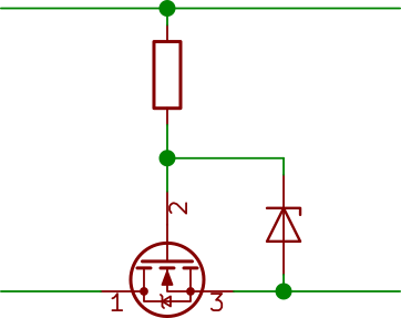
I use this on all my PCBs with removable batterys. Luxury upgrade: a reverse voltage indicator:
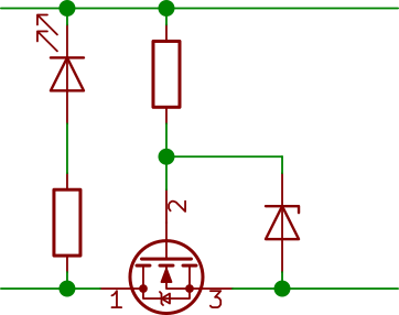
Add a Zener parallel to the LED if you have a wide expectet input voltage range. -
@eiten said in CNC PCB milling:
The explanation why it is polarized is because in fact, it used to be a diode in older revisions, check out Step 7 here.
Yeah, let's look at that:
D1(Diode) was intended to prevent users from damaging the board by accidentally reversing the polarity on the high voltage line. Unfortunately this feature was abandoned because I could not find a big enough Diode that would handle 6 amps at a time and still fit on the board. The work around for this is to solder in a jumper wire (Yellow Wire).
LOL. This excuse just doesn't ring true. I mean, by version 3 he still couldn't manage to find space on the board for a suitable diode? Nevermind that he could have used an alternative for reverse polarity protection, like a mosfet, which also wouldn't have incurred as large a voltage drop.
Well, speaking of diodes, I don't see any TVS or zener diodes on this board for protection against back EMF. I guess that's just assumed to be handled by the driver modules?
@NeverDie said in CNC PCB milling:
speaking of diodes, I don't see any TVS or zener diodes on this board for protection against back EMF. I guess that's just assumed to be handled by the driver modules?
Well, according to Pololu, capacitors are to be used for that instead:
Warning: This carrier board uses low-ESR ceramic capacitors, which makes it susceptible to destructive LC voltage spikes, especially when using power leads longer than a few inches. Under the right conditions, these spikes can exceed the 35 V maximum voltage rating for the A4988 and permanently damage the board, even when the motor supply voltage is as low as 12 V. One way to protect the driver from such spikes is to put a large (at least 47 µF) electrolytic capacitor across motor power (VMOT) and ground somewhere close to the board.
Actually, this might be better anyway, since different driver boards may have different maximum voltages, and using a capacitor would adapt to that.
So, it remains to be seen whether the given 50v rating on a 100uF capacitor is enough if I were to raise the supply voltage to 45v to drive DRV8825's at their maximum voltage. The board design may not have accounted for that, since it sets an arbitrary limit of 36v for input voltage, as stated on the silk screen. I guess the way to test it experimentally would be to start at 35v and then creep up the voltage while monitoring an in-use capacitor in situ on an oscilloscope while driving the stepper at maximum acceleration and then suddenly stopping. I presume that would be the worst case scenario. However, I'm not sure what the gcode for that would be. Anyone know? If not, I may just have to settle for jogging the stepper around and take measurements based on that instead.
-
-
Anyhow, I ordered one of these tramming tools:
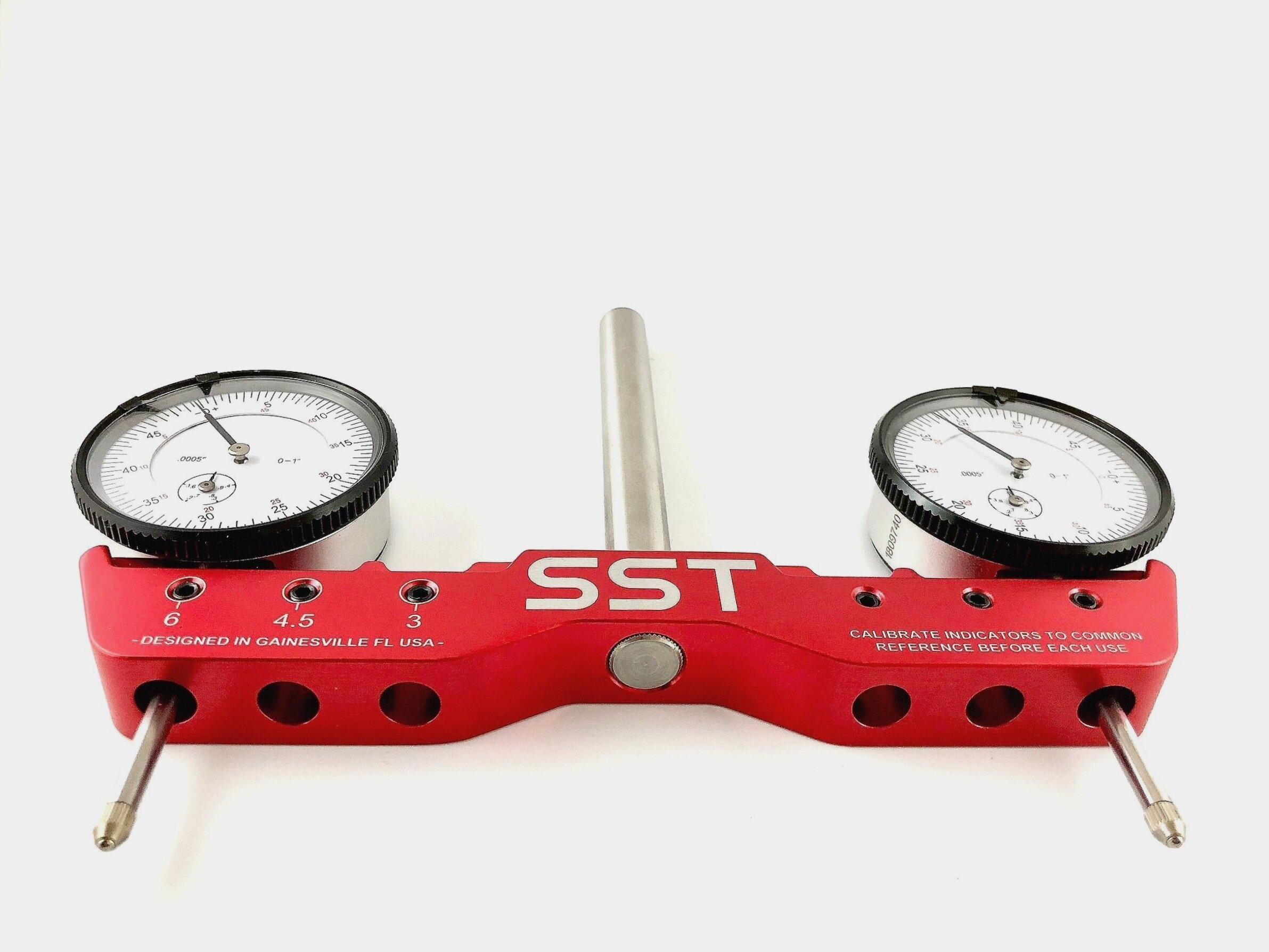
so that I can do accurate repeatability tests on the z-axis, and that is because I will need to be deadnuts accurate if I am to selectively CNC mill the solder mask off from a PCB without destroying the underlying solder pads. i'm not sure I will have enough headroom on the z-axis to fit this tool into place--or use it for that matter--so I'll just have to see how that goes after it arrives. A lot may depend on how far I can plunge the dial indicators before they bottom out. -
By the way, I just now found a online outfit which will cnc laser cut steel up to 1" thick. Their name? Yeah, you guessed it: oshcut.
https://www.oshcut.com
A really interesting option for my next CNC after this one would be to design the whole thing in CAD and then have it laser cut out of stainless steel. As compared to Chinese aluminum extrusion CNC's, I can see this as having two advantages: 1. Steel is far stronger and more rigid than aluminum, and so it would be lightyears ahead in that regard, and 2. I'm guessing the parts would be far more dimensionally accurate than whatever gets banged out in China for shipment through Aliexpress. In the past what has held me back from building a CNC from scratch is the need to precisely drill all the holes with just exactlly right amount of spacing, parallelism, and perpendicularity. However, with access to cnc laser cut steel, I presumably get all the dimensional accuracy I would need at no extra cost.Fanciful? I think not. A kid in Poland did his own CNC design and had the steel parts lasercut in Poland. In just the past few days he finished putting it together, and it looks like a pretty reasonable design using both ballscrews and steel rail guides, held together will steel gussets that he designed himself in CAD:
https://www.youtube.com/watch?v=5jFCecZdbGsI'd say it looks better than most of what China is selling. In fact, he's giving his design files away for free, so if you wanted to I suppose you could have the exact same parts lasercut and shipped to your door. Pretty cool! :sunglasses: This looks like it could (finally!) be the start of truly open source CNC designs, as compared to the past where you more or less had to buy all the custom cut parts from somebody else, who, of course, was selling them at a mark-up relative to their own costs.
-
Anyhow, I ordered one of these tramming tools:
so that I can do accurate repeatability tests on the z-axis, and that is because I will need to be deadnuts accurate if I am to selectively CNC mill the solder mask off from a PCB without destroying the underlying solder pads. i'm not sure I will have enough headroom on the z-axis to fit this tool into place--or use it for that matter--so I'll just have to see how that goes after it arrives. A lot may depend on how far I can plunge the dial indicators before they bottom out.@NeverDie said in CNC PCB milling:
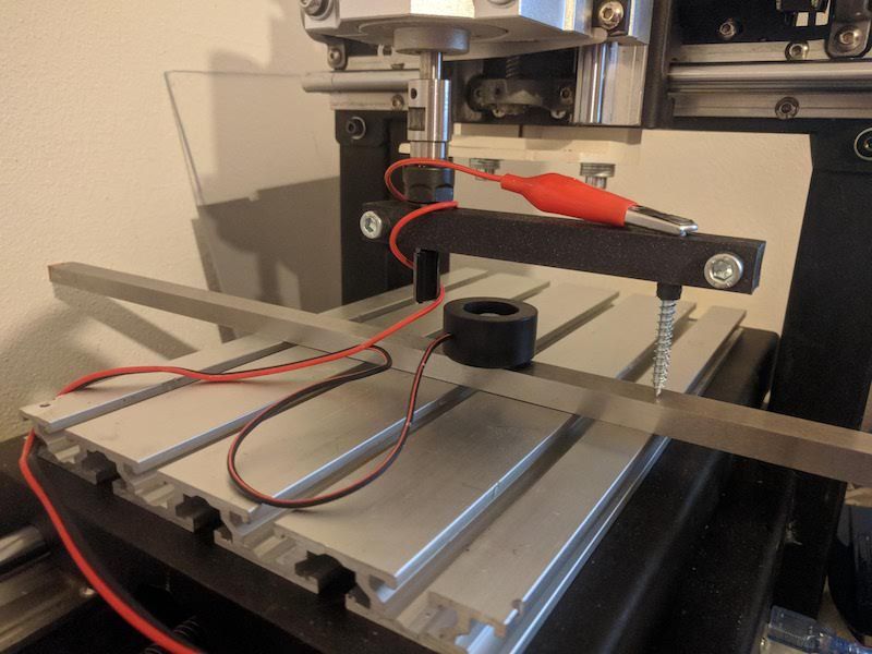
so that I can do accurate repeatability tests on the z-axis, and that is because I will need to be deadnuts accurate if I am to selectively CNC mill the solder mask off from a PCB without destroying the underlying solder pads. i'm not sure I will have enough headroom on the z-axis to fit this tool into place--or use it for that matter--so I'll just have to see how that goes after it arrives. A lot may depend on how far I can plunge the dial indicators before they bottom out.
Dial based tramming depends on table being flat, otherwise result is so so.
Eventually I've used 3d printed bar with holes for 1/4" stub bit to mount into collet
and 1/8" on other side for a scrap v-bit with probe clip attached. It allows to tram spindle in X and Y directions compared to dial gauge ( only X direction, due to not enough clerance under X axis frame)Yields about the same result as dial method against uneven table almost for free. Putting MDF spoil board, and levelling, helps a bit but then one gets "waves" if the spindle is not perpendicular to the table and given that MDF is not conductive, I couldn't use probe again to re-measure.
That was solved by using steel gauge plate (I used 10x15x500mm) to serve as other end of the probe. It takes only few facing iterations to level bed with facing bit, in each direction (X and Y). Also gauge plate across whole table takes care of evening 'waves' and it's still cheaper than a good dial gauge (not speaking about dedicated tramming contraption above). Caveat is that it's much slower than using
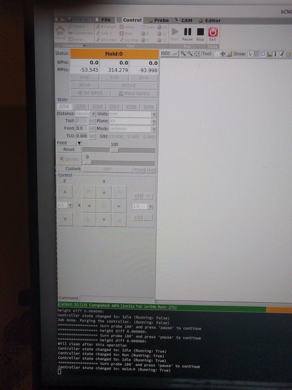
dial gauge due to slow probing but in my case it was more repeatable so it's hard to tell which method was slower in the end.With bCNC it's possible to use gcode macro to do tedious work of probing, so one needs only to manually rotate probe 180° and press a button to see which direction axis is skewed.
-
Have any of you tried to make a vacuum table?
When it comes to the solder mask. Based on video I say this is done easier bij using UV exposure only. If you are using UV paint anyway, then you might as well print the design on a transparent sheet.
-
@NeverDie said in CNC PCB milling:
so that I can do accurate repeatability tests on the z-axis, and that is because I will need to be deadnuts accurate if I am to selectively CNC mill the solder mask off from a PCB without destroying the underlying solder pads. i'm not sure I will have enough headroom on the z-axis to fit this tool into place--or use it for that matter--so I'll just have to see how that goes after it arrives. A lot may depend on how far I can plunge the dial indicators before they bottom out.
Dial based tramming depends on table being flat, otherwise result is so so.
Eventually I've used 3d printed bar with holes for 1/4" stub bit to mount into collet
and 1/8" on other side for a scrap v-bit with probe clip attached. It allows to tram spindle in X and Y directions compared to dial gauge ( only X direction, due to not enough clerance under X axis frame)Yields about the same result as dial method against uneven table almost for free. Putting MDF spoil board, and levelling, helps a bit but then one gets "waves" if the spindle is not perpendicular to the table and given that MDF is not conductive, I couldn't use probe again to re-measure.
That was solved by using steel gauge plate (I used 10x15x500mm) to serve as other end of the probe. It takes only few facing iterations to level bed with facing bit, in each direction (X and Y). Also gauge plate across whole table takes care of evening 'waves' and it's still cheaper than a good dial gauge (not speaking about dedicated tramming contraption above). Caveat is that it's much slower than using
dial gauge due to slow probing but in my case it was more repeatable so it's hard to tell which method was slower in the end.With bCNC it's possible to use gcode macro to do tedious work of probing, so one needs only to manually rotate probe 180° and press a button to see which direction axis is skewed.
@niallain said in CNC PCB milling:
Eventually I've used 3d printed bar with holes for 1/4" stub bit to mount into collet
and 1/8" on other side for a scrap v-bit with probe clip attached. It allows to tram spindle in X and Y directions compared to dial gauge ( only X direction, due to not enough clerance under X axis frame)Do you have any pictures you can post?
-
Have any of you tried to make a vacuum table?
When it comes to the solder mask. Based on video I say this is done easier bij using UV exposure only. If you are using UV paint anyway, then you might as well print the design on a transparent sheet.
@Joerideman said in CNC PCB milling:
Have any of you tried to make a vacuum table?
No, I haven't. Why do you ask?
When it comes to the solder mask. Based on video I say this is done easier bij using UV exposure only. If you are using UV paint anyway, then you might as well print the design on a transparent sheet.
Yes, there's more than one way to tackle the problem. The method you describe is one of the more common ones, but it seems to involve more manual processing. It would be nice if someone who had tried both methods posted the pros and cons of each method.
-
I suppose the GRBL capacitor rating may soon be a moot issue anyway, as the servo42A closed loop driver accepts an input voltage of only 12-24v, and, not surprisingly, it appears to have its own back EMF cap on its driverboard:

@NeverDie said in CNC PCB milling:
I suppose the GRBL capacitor rating may soon be a moot issue anyway, as the servo42A closed loop driver accepts an input voltage of only 12-24v, and, not surprisingly, it appears to have its own back EMF cap on its driverboard:
The original mechaduino v0.2 accepted up to 35v:
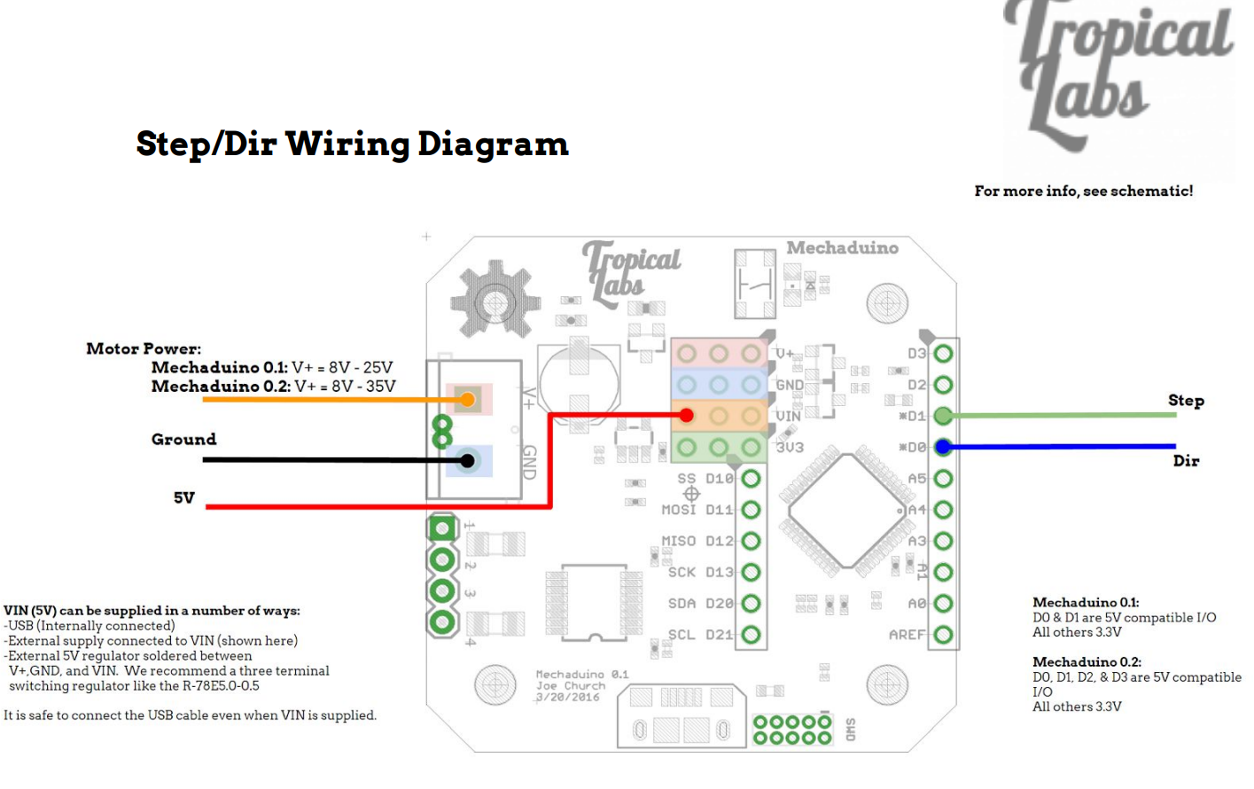
So, because the clone that I purchased allows for only 24v input, it's an unfortunate downgrade from the original. :(
-
@niallain said in CNC PCB milling:
Eventually I've used 3d printed bar with holes for 1/4" stub bit to mount into collet
and 1/8" on other side for a scrap v-bit with probe clip attached. It allows to tram spindle in X and Y directions compared to dial gauge ( only X direction, due to not enough clerance under X axis frame)Do you have any pictures you can post?
@NeverDie said in CNC PCB milling:
@niallain said in CNC PCB milling:
Eventually I've used 3d printed bar with holes for 1/4" stub bit to mount into collet
and 1/8" on other side for a scrap v-bit with probe clip attached. It allows to tram spindle in X and Y directions compared to dial gauge ( only X direction, due to not enough clerance under X axis frame)Do you have any pictures you can post?
Thanks to you, I finally 'finished' replacing arduino 'nano' with 'mega' :) , that I were putting off for a month now, since GRBL on it provides software backlash and axis skew compensations (I gave up on trying to square/fix machine mechanically).
Back to the topic, there are lots of videos on youtube where spindle is trammed using bar and paper method, so this is nothing new just a small improvement to reduce manual work and improve repeatability without expensive equipment.
Before doing it, I face spoil-board perpendicular to bar to make it level,
which results in ridges if spindle is not perpendicular to table.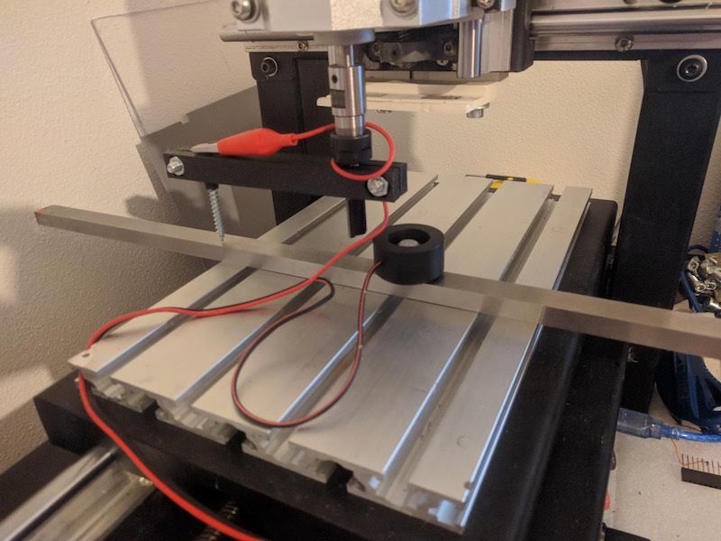
the same can be done for Y axis, just face board/turn bar 90 degrees.
Assuming you are in EU, gauge plate I got from here, it's my source for 'cheapish' but decent endmills compared to the rest of sources, I know of, within EU. -
Hi executivul! Great to hear from you again.
@executivul said in CNC PCB milling:
@NeverDie Just get any Atmega328 board (Uno, Nano) and flash grbl 1.1f and wire it to whatever drivers you have (now I'm using hybrid closed loop servos, but I've used TB6560 in the past).
On Aliexpress I notice there are these drivers (one per axis) that it sounds as though you are using. Some of them (usually blue) are self-described as "Hybrid", whereas others (often Green or some other color) are self-described as "closed loop." I haven't tried either one, but I get the impression that the "Hybrid" drivers function closed loop as well, and it sounds as though that is what you are doing. If that is the case, what, if any, functional difference is there between the self-described "hybrid" drivers and the self-described "closed-loop" drivers? I assume you know what I'm referring to, but if not, let me know and I'll post pictures and links in order to clarify.
@NeverDie Here are my steppers I currently use on my 3040 cnc: https://www.ebay.co.uk/itm/Nema23-2Nm-Closed-Loop-Stepper-Motor-Driver-3phase-Hybrid-Easy-DC-Servo-Kit-CNC/254675291058?hash=item3b4bd48bb2:g:FcsAAOSwAuZX4lcl
-
@NeverDie Here are my steppers I currently use on my 3040 cnc: https://www.ebay.co.uk/itm/Nema23-2Nm-Closed-Loop-Stepper-Motor-Driver-3phase-Hybrid-Easy-DC-Servo-Kit-CNC/254675291058?hash=item3b4bd48bb2:g:FcsAAOSwAuZX4lcl
@executivul I notice that closed looop ethercat is also starting to become popular:
https://www.aliexpress.com/item/33028892255.html?spm=a2g0o.productlist.0.0.4a3acc12R4bh4z&ad_pvid=202008201300179940172292214280005385422_2&s=pEspecially for LinuxCNC and Mach3/4 users. I don't know enough about either of those software packages to know what, if any, advantages they may have, but the downside seems clear enough: you need to worry about what kind of jitter and lag the PC you run it on may have.
Maybe that's where the closed loop helps out? The ethernet affords some noise immunity. Not sure to what degree, or not, that noise is even a problem with typical non-ethernet GRBL driven configurations.I notice that the new TMC5160's have motion planning built into the chips themselves, though I haven't yet seen any configurations which take advantage of that. Sounds intriguing, as it would be able to capitalize on any feedback practically instantaneously. Maybe it will be a game changer? The TMC5160 datasheet makes some vague references to closed loop.
-
@executivul I notice that closed looop ethercat is also starting to become popular:
https://www.aliexpress.com/item/33028892255.html?spm=a2g0o.productlist.0.0.4a3acc12R4bh4z&ad_pvid=202008201300179940172292214280005385422_2&s=pEspecially for LinuxCNC and Mach3/4 users. I don't know enough about either of those software packages to know what, if any, advantages they may have, but the downside seems clear enough: you need to worry about what kind of jitter and lag the PC you run it on may have.
Maybe that's where the closed loop helps out? The ethernet affords some noise immunity. Not sure to what degree, or not, that noise is even a problem with typical non-ethernet GRBL driven configurations.I notice that the new TMC5160's have motion planning built into the chips themselves, though I haven't yet seen any configurations which take advantage of that. Sounds intriguing, as it would be able to capitalize on any feedback practically instantaneously. Maybe it will be a game changer? The TMC5160 datasheet makes some vague references to closed loop.
@NeverDie EtherCAT is simply awesome. Over the years I developed multiple EtherCAT masters and slaves, and used it in many industrial machine control solutions.
It has proven extremely useful for realtime distributed control and offers great flexibility.
Jitter on bus cycle deserves attention, but on the other hand even windows can run an EtherCAT master; it just all depends on your application and control requirements.
In the case of small CNC and 3D printers it may be slight overkill however.
Let me know if you would like to go deeper into the topic, or have specific questions!