CNC PCB milling
-
Anyhow, I ordered one of these tramming tools:
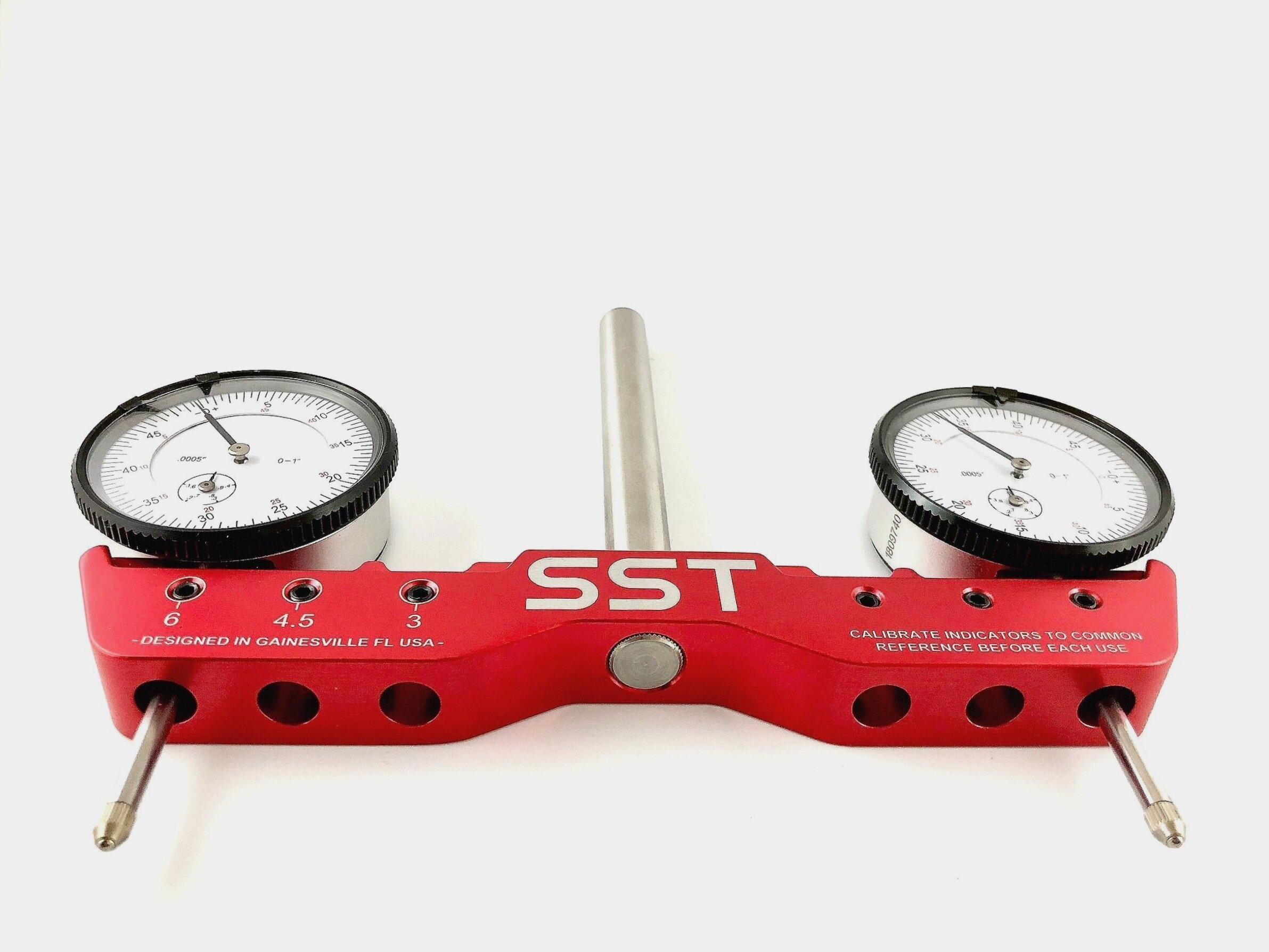
so that I can do accurate repeatability tests on the z-axis, and that is because I will need to be deadnuts accurate if I am to selectively CNC mill the solder mask off from a PCB without destroying the underlying solder pads. i'm not sure I will have enough headroom on the z-axis to fit this tool into place--or use it for that matter--so I'll just have to see how that goes after it arrives. A lot may depend on how far I can plunge the dial indicators before they bottom out.@NeverDie said in CNC PCB milling:
so that I can do accurate repeatability tests on the z-axis, and that is because I will need to be deadnuts accurate if I am to selectively CNC mill the solder mask off from a PCB without destroying the underlying solder pads. i'm not sure I will have enough headroom on the z-axis to fit this tool into place--or use it for that matter--so I'll just have to see how that goes after it arrives. A lot may depend on how far I can plunge the dial indicators before they bottom out.
Dial based tramming depends on table being flat, otherwise result is so so.
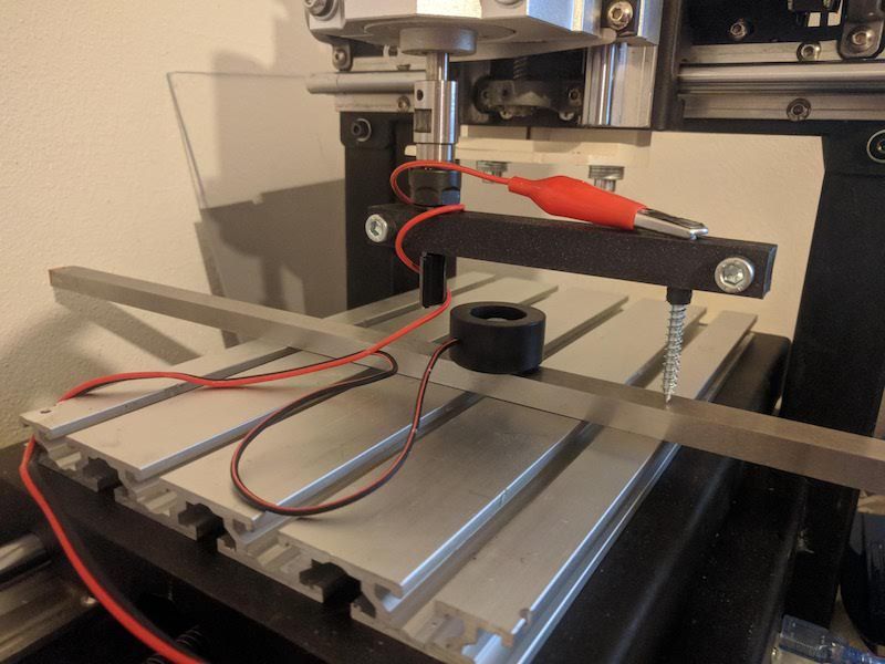
Eventually I've used 3d printed bar with holes for 1/4" stub bit to mount into collet
and 1/8" on other side for a scrap v-bit with probe clip attached. It allows to tram spindle in X and Y directions compared to dial gauge ( only X direction, due to not enough clerance under X axis frame)Yields about the same result as dial method against uneven table almost for free. Putting MDF spoil board, and levelling, helps a bit but then one gets "waves" if the spindle is not perpendicular to the table and given that MDF is not conductive, I couldn't use probe again to re-measure.
That was solved by using steel gauge plate (I used 10x15x500mm) to serve as other end of the probe. It takes only few facing iterations to level bed with facing bit, in each direction (X and Y). Also gauge plate across whole table takes care of evening 'waves' and it's still cheaper than a good dial gauge (not speaking about dedicated tramming contraption above). Caveat is that it's much slower than using
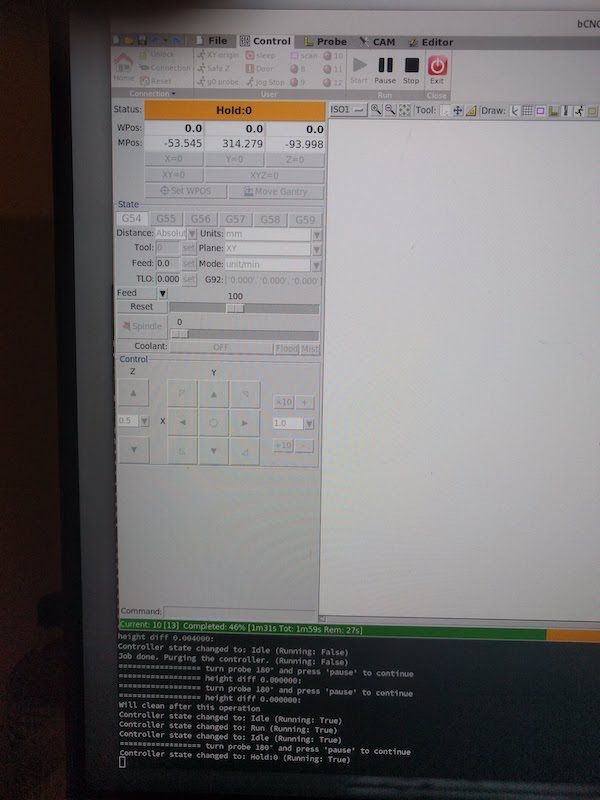
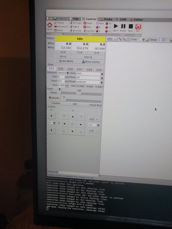
dial gauge due to slow probing but in my case it was more repeatable so it's hard to tell which method was slower in the end.With bCNC it's possible to use gcode macro to do tedious work of probing, so one needs only to manually rotate probe 180° and press a button to see which direction axis is skewed.
-
Have any of you tried to make a vacuum table?
When it comes to the solder mask. Based on video I say this is done easier bij using UV exposure only. If you are using UV paint anyway, then you might as well print the design on a transparent sheet.
-
@NeverDie said in CNC PCB milling:
so that I can do accurate repeatability tests on the z-axis, and that is because I will need to be deadnuts accurate if I am to selectively CNC mill the solder mask off from a PCB without destroying the underlying solder pads. i'm not sure I will have enough headroom on the z-axis to fit this tool into place--or use it for that matter--so I'll just have to see how that goes after it arrives. A lot may depend on how far I can plunge the dial indicators before they bottom out.
Dial based tramming depends on table being flat, otherwise result is so so.
Eventually I've used 3d printed bar with holes for 1/4" stub bit to mount into collet
and 1/8" on other side for a scrap v-bit with probe clip attached. It allows to tram spindle in X and Y directions compared to dial gauge ( only X direction, due to not enough clerance under X axis frame)Yields about the same result as dial method against uneven table almost for free. Putting MDF spoil board, and levelling, helps a bit but then one gets "waves" if the spindle is not perpendicular to the table and given that MDF is not conductive, I couldn't use probe again to re-measure.
That was solved by using steel gauge plate (I used 10x15x500mm) to serve as other end of the probe. It takes only few facing iterations to level bed with facing bit, in each direction (X and Y). Also gauge plate across whole table takes care of evening 'waves' and it's still cheaper than a good dial gauge (not speaking about dedicated tramming contraption above). Caveat is that it's much slower than using
dial gauge due to slow probing but in my case it was more repeatable so it's hard to tell which method was slower in the end.With bCNC it's possible to use gcode macro to do tedious work of probing, so one needs only to manually rotate probe 180° and press a button to see which direction axis is skewed.
@niallain said in CNC PCB milling:
Eventually I've used 3d printed bar with holes for 1/4" stub bit to mount into collet
and 1/8" on other side for a scrap v-bit with probe clip attached. It allows to tram spindle in X and Y directions compared to dial gauge ( only X direction, due to not enough clerance under X axis frame)Do you have any pictures you can post?
-
Have any of you tried to make a vacuum table?
When it comes to the solder mask. Based on video I say this is done easier bij using UV exposure only. If you are using UV paint anyway, then you might as well print the design on a transparent sheet.
@Joerideman said in CNC PCB milling:
Have any of you tried to make a vacuum table?
No, I haven't. Why do you ask?
When it comes to the solder mask. Based on video I say this is done easier bij using UV exposure only. If you are using UV paint anyway, then you might as well print the design on a transparent sheet.
Yes, there's more than one way to tackle the problem. The method you describe is one of the more common ones, but it seems to involve more manual processing. It would be nice if someone who had tried both methods posted the pros and cons of each method.
-
I suppose the GRBL capacitor rating may soon be a moot issue anyway, as the servo42A closed loop driver accepts an input voltage of only 12-24v, and, not surprisingly, it appears to have its own back EMF cap on its driverboard:

@NeverDie said in CNC PCB milling:
I suppose the GRBL capacitor rating may soon be a moot issue anyway, as the servo42A closed loop driver accepts an input voltage of only 12-24v, and, not surprisingly, it appears to have its own back EMF cap on its driverboard:
The original mechaduino v0.2 accepted up to 35v:
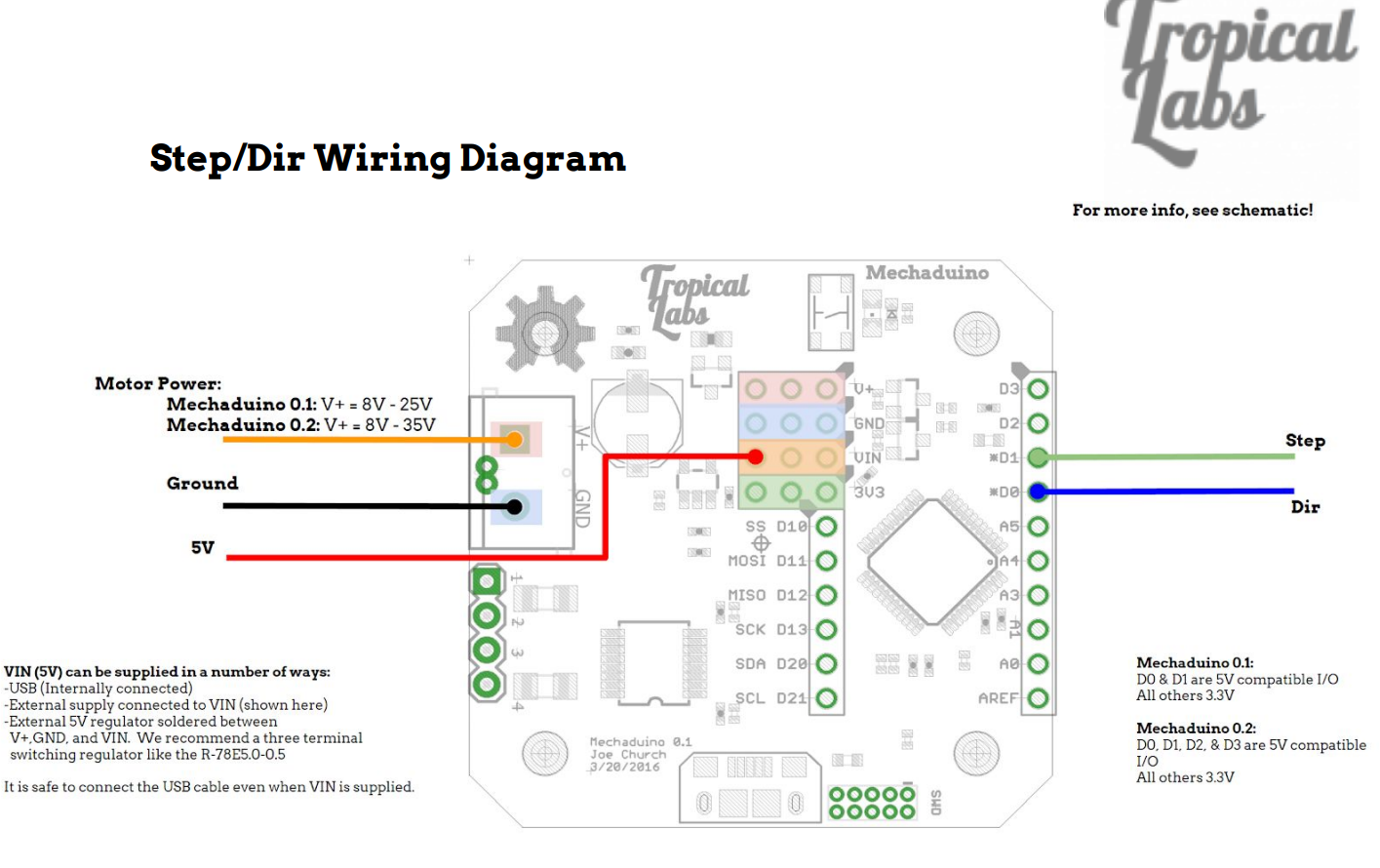
So, because the clone that I purchased allows for only 24v input, it's an unfortunate downgrade from the original. :(
-
@niallain said in CNC PCB milling:
Eventually I've used 3d printed bar with holes for 1/4" stub bit to mount into collet
and 1/8" on other side for a scrap v-bit with probe clip attached. It allows to tram spindle in X and Y directions compared to dial gauge ( only X direction, due to not enough clerance under X axis frame)Do you have any pictures you can post?
@NeverDie said in CNC PCB milling:
@niallain said in CNC PCB milling:
Eventually I've used 3d printed bar with holes for 1/4" stub bit to mount into collet
and 1/8" on other side for a scrap v-bit with probe clip attached. It allows to tram spindle in X and Y directions compared to dial gauge ( only X direction, due to not enough clerance under X axis frame)Do you have any pictures you can post?
Thanks to you, I finally 'finished' replacing arduino 'nano' with 'mega' :) , that I were putting off for a month now, since GRBL on it provides software backlash and axis skew compensations (I gave up on trying to square/fix machine mechanically).
Back to the topic, there are lots of videos on youtube where spindle is trammed using bar and paper method, so this is nothing new just a small improvement to reduce manual work and improve repeatability without expensive equipment.
Before doing it, I face spoil-board perpendicular to bar to make it level,
which results in ridges if spindle is not perpendicular to table.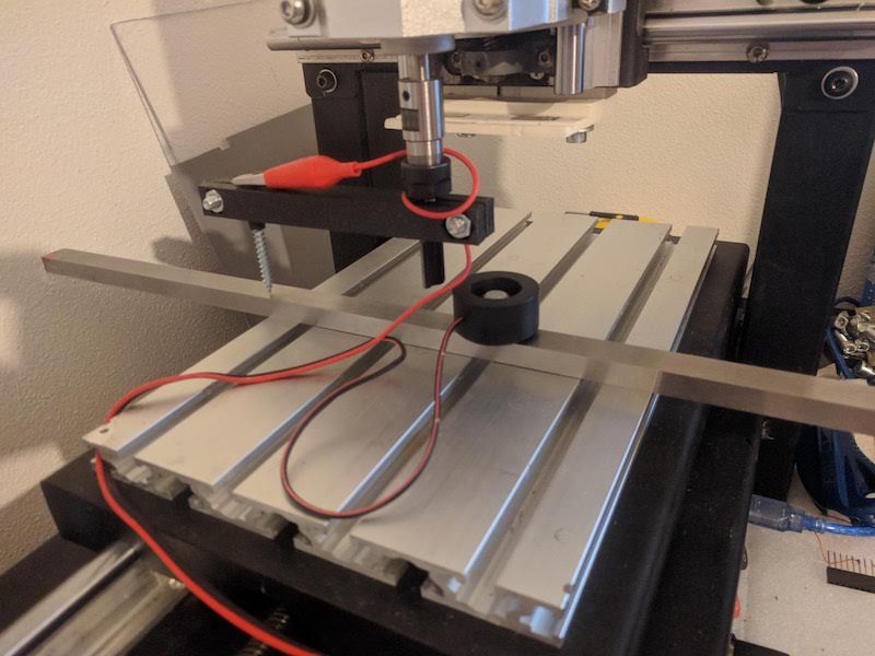
the same can be done for Y axis, just face board/turn bar 90 degrees.
Assuming you are in EU, gauge plate I got from here, it's my source for 'cheapish' but decent endmills compared to the rest of sources, I know of, within EU. -
Hi executivul! Great to hear from you again.
@executivul said in CNC PCB milling:
@NeverDie Just get any Atmega328 board (Uno, Nano) and flash grbl 1.1f and wire it to whatever drivers you have (now I'm using hybrid closed loop servos, but I've used TB6560 in the past).
On Aliexpress I notice there are these drivers (one per axis) that it sounds as though you are using. Some of them (usually blue) are self-described as "Hybrid", whereas others (often Green or some other color) are self-described as "closed loop." I haven't tried either one, but I get the impression that the "Hybrid" drivers function closed loop as well, and it sounds as though that is what you are doing. If that is the case, what, if any, functional difference is there between the self-described "hybrid" drivers and the self-described "closed-loop" drivers? I assume you know what I'm referring to, but if not, let me know and I'll post pictures and links in order to clarify.
@NeverDie Here are my steppers I currently use on my 3040 cnc: https://www.ebay.co.uk/itm/Nema23-2Nm-Closed-Loop-Stepper-Motor-Driver-3phase-Hybrid-Easy-DC-Servo-Kit-CNC/254675291058?hash=item3b4bd48bb2:g:FcsAAOSwAuZX4lcl
-
@NeverDie Here are my steppers I currently use on my 3040 cnc: https://www.ebay.co.uk/itm/Nema23-2Nm-Closed-Loop-Stepper-Motor-Driver-3phase-Hybrid-Easy-DC-Servo-Kit-CNC/254675291058?hash=item3b4bd48bb2:g:FcsAAOSwAuZX4lcl
@executivul I notice that closed looop ethercat is also starting to become popular:
https://www.aliexpress.com/item/33028892255.html?spm=a2g0o.productlist.0.0.4a3acc12R4bh4z&ad_pvid=202008201300179940172292214280005385422_2&s=pEspecially for LinuxCNC and Mach3/4 users. I don't know enough about either of those software packages to know what, if any, advantages they may have, but the downside seems clear enough: you need to worry about what kind of jitter and lag the PC you run it on may have.
Maybe that's where the closed loop helps out? The ethernet affords some noise immunity. Not sure to what degree, or not, that noise is even a problem with typical non-ethernet GRBL driven configurations.I notice that the new TMC5160's have motion planning built into the chips themselves, though I haven't yet seen any configurations which take advantage of that. Sounds intriguing, as it would be able to capitalize on any feedback practically instantaneously. Maybe it will be a game changer? The TMC5160 datasheet makes some vague references to closed loop.
-
@executivul I notice that closed looop ethercat is also starting to become popular:
https://www.aliexpress.com/item/33028892255.html?spm=a2g0o.productlist.0.0.4a3acc12R4bh4z&ad_pvid=202008201300179940172292214280005385422_2&s=pEspecially for LinuxCNC and Mach3/4 users. I don't know enough about either of those software packages to know what, if any, advantages they may have, but the downside seems clear enough: you need to worry about what kind of jitter and lag the PC you run it on may have.
Maybe that's where the closed loop helps out? The ethernet affords some noise immunity. Not sure to what degree, or not, that noise is even a problem with typical non-ethernet GRBL driven configurations.I notice that the new TMC5160's have motion planning built into the chips themselves, though I haven't yet seen any configurations which take advantage of that. Sounds intriguing, as it would be able to capitalize on any feedback practically instantaneously. Maybe it will be a game changer? The TMC5160 datasheet makes some vague references to closed loop.
@NeverDie EtherCAT is simply awesome. Over the years I developed multiple EtherCAT masters and slaves, and used it in many industrial machine control solutions.
It has proven extremely useful for realtime distributed control and offers great flexibility.
Jitter on bus cycle deserves attention, but on the other hand even windows can run an EtherCAT master; it just all depends on your application and control requirements.
In the case of small CNC and 3D printers it may be slight overkill however.
Let me know if you would like to go deeper into the topic, or have specific questions! -
@executivul I notice that closed looop ethercat is also starting to become popular:
https://www.aliexpress.com/item/33028892255.html?spm=a2g0o.productlist.0.0.4a3acc12R4bh4z&ad_pvid=202008201300179940172292214280005385422_2&s=pEspecially for LinuxCNC and Mach3/4 users. I don't know enough about either of those software packages to know what, if any, advantages they may have, but the downside seems clear enough: you need to worry about what kind of jitter and lag the PC you run it on may have.
Maybe that's where the closed loop helps out? The ethernet affords some noise immunity. Not sure to what degree, or not, that noise is even a problem with typical non-ethernet GRBL driven configurations.I notice that the new TMC5160's have motion planning built into the chips themselves, though I haven't yet seen any configurations which take advantage of that. Sounds intriguing, as it would be able to capitalize on any feedback practically instantaneously. Maybe it will be a game changer? The TMC5160 datasheet makes some vague references to closed loop.
@NeverDie These closed control loops have got really good traction lately, these days there is a sprawl of new/cheaper devices/clones. I've used mine without issue for 2 years now.
My problem was frequent binding of the machine. I have a 60,000rpm spindle and I normally use 1400mm/min speed and 300mm/s^2 acceleration. The machine itself is far from perfect, sometimes I can hear it knocking, and with older steppers and drivers I lost a few steps every time it jammed, resulting in 0.1-0.3mm of error at the end of a longer milling process.
The culprit is either some misalignment and lack of parallelism or some of the balls have flat spots. The binding does not occur in the same place or direction every single time, so I believe the balls are more likely to be the cause. The solution would be a complete rebuild using higher quality linear rails, but the the price and the time needed to do it makes me leave it as it is since I can mill 0.15mm isolation with 0.25mm traces for smd and also large 20cm x 30cm boards for through hole projects (mostly). -
@NeverDie These closed control loops have got really good traction lately, these days there is a sprawl of new/cheaper devices/clones. I've used mine without issue for 2 years now.
My problem was frequent binding of the machine. I have a 60,000rpm spindle and I normally use 1400mm/min speed and 300mm/s^2 acceleration. The machine itself is far from perfect, sometimes I can hear it knocking, and with older steppers and drivers I lost a few steps every time it jammed, resulting in 0.1-0.3mm of error at the end of a longer milling process.
The culprit is either some misalignment and lack of parallelism or some of the balls have flat spots. The binding does not occur in the same place or direction every single time, so I believe the balls are more likely to be the cause. The solution would be a complete rebuild using higher quality linear rails, but the the price and the time needed to do it makes me leave it as it is since I can mill 0.15mm isolation with 0.25mm traces for smd and also large 20cm x 30cm boards for through hole projects (mostly).@executivul So even with the closed loop it's still off at the end? That's hard to wrap my head around.
I guess the ultimate solution would be DRO's then. Short of that, or the improvements you're talking about, maybe you could re-zero periodically during the job? You're getting great results, though, so I don't blame you for leaving it alone.
-
@NeverDie EtherCAT is simply awesome. Over the years I developed multiple EtherCAT masters and slaves, and used it in many industrial machine control solutions.
It has proven extremely useful for realtime distributed control and offers great flexibility.
Jitter on bus cycle deserves attention, but on the other hand even windows can run an EtherCAT master; it just all depends on your application and control requirements.
In the case of small CNC and 3D printers it may be slight overkill however.
Let me know if you would like to go deeper into the topic, or have specific questions!@Yveaux said in CNC PCB milling:
@NeverDie EtherCAT is simply awesome. Over the years I developed multiple EtherCAT masters and slaves, and used it in many industrial machine control solutions.
It has proven extremely useful for realtime distributed control and offers great flexibility.
Jitter on bus cycle deserves attention, but on the other hand even windows can run an EtherCAT master; it just all depends on your application and control requirements.
In the case of small CNC and 3D printers it may be slight overkill however.
Let me know if you would like to go deeper into the topic, or have specific questions!That's great! Do you think there's much hope of seeing a greatly cost-reduced arduino version of ethercat anytime soon? I mean, by way of analogy, for a long while wi-fi seemed intractably expensive, and even the expensive wi-fi breakouts for arduino's seemed pretty dodgy. Then out of the blue ESP8266 suddenly made good arduino wi-fi possible for cheap.
-
@Yveaux said in CNC PCB milling:
@NeverDie EtherCAT is simply awesome. Over the years I developed multiple EtherCAT masters and slaves, and used it in many industrial machine control solutions.
It has proven extremely useful for realtime distributed control and offers great flexibility.
Jitter on bus cycle deserves attention, but on the other hand even windows can run an EtherCAT master; it just all depends on your application and control requirements.
In the case of small CNC and 3D printers it may be slight overkill however.
Let me know if you would like to go deeper into the topic, or have specific questions!That's great! Do you think there's much hope of seeing a greatly cost-reduced arduino version of ethercat anytime soon? I mean, by way of analogy, for a long while wi-fi seemed intractably expensive, and even the expensive wi-fi breakouts for arduino's seemed pretty dodgy. Then out of the blue ESP8266 suddenly made good arduino wi-fi possible for cheap.
@NeverDie EtherCAT requires a dedicated ASIC (e.g. Beckhoff ET1100) or FPGA IP Core.
There have been some developments where MPU & EtherCAT slave controller were integrated into a single piece of silicon (TI, Renesas, Microchip) but these are less popular than the ET1100.
For distributed IO it is an awesome technology, but when all IO and controller can be located onto a single board (like with most hobby CNCs) it is overkill, at least for the masses.
But again, you never know what nice lowcost EtherCAT solution could be coming our way.http://yveaux.blogspot.nl
-
@NeverDie EtherCAT requires a dedicated ASIC (e.g. Beckhoff ET1100) or FPGA IP Core.
There have been some developments where MPU & EtherCAT slave controller were integrated into a single piece of silicon (TI, Renesas, Microchip) but these are less popular than the ET1100.
For distributed IO it is an awesome technology, but when all IO and controller can be located onto a single board (like with most hobby CNCs) it is overkill, at least for the masses.
But again, you never know what nice lowcost EtherCAT solution could be coming our way.@Yveaux That makes sense to me. If people are mainly doing it for noise immunity, I'm reasonably sure that differential op-amps (which are cheap) and twisted pair wiring (which is cheap) will do the business. That's how ethernet does it. If that's still not enough, then add shielding. Also, the more twisting the better. At least, I would think that it would be sufficient for a home environment.
I'll be testing this theory with the closed-loop stepper drivers that I'll be installing, since with those it will be the data coms between the GRBL board and the stepper drivers that will be running across long wires instead of power pulses to the steppers, where noise didn't really matter. I guess we'll see!
-
Hey, I have trouble understanding the last 10 posts.
It sounds like this go's beyond the PCB milling?
What are you aiming to achieve?
-
Hey, I have trouble understanding the last 10 posts.
It sounds like this go's beyond the PCB milling?
What are you aiming to achieve?
@Joerideman said in CNC PCB milling:
Hey, I have trouble understanding the last 10 posts.
It sounds like this go's beyond the PCB milling?
What are you aiming to achieve?
No, the aim is still pcb milling. More specifically: PCB milling at fine pitch and whatever might support that. Regular through-hole milling is something that just about any PCB mill can handle, so the discussion has shifted to milling for newer SMD parts, where the pitch between pads can be quite challenging for some mills, like mine for example. Then the question becomes: which are the best bang/buck upgrades (or even just calibrations) that will get you there.
-
So, I have seen that with a popular 3018 CNC a atmega328p-au can be milled.
0.2mm traces with 0.2mm clearance can be routed.
What specs are you going for?
-
So, I have seen that with a popular 3018 CNC a atmega328p-au can be milled.
0.2mm traces with 0.2mm clearance can be routed.
What specs are you going for?
@Joerideman said in CNC PCB milling:
So, I have seen that with a popular 3018 CNC a atmega328p-au can be milled.
0.2mm traces with 0.2mm clearance can be routed.
What specs are you going for?
I thought the atmega328p had wider pitch than that, as I have etched those before. Nonethmeless, where did you see a 3018 that could do those specs? I think for now, if I'm understanding you correctly, that would be good enough, at least for me. That would effectively be a 0.4mm pitch, right? Measured center to center from one pad to the next.
I don't think my rig is any worse than a 3018. Most low-end CNC's seem pretty similar, with aluminum extrusion frames, acme screws, round rods and inexpensive linear bearings for glides, and dubious spindles, dodgy collets, and questionable z-axis reinforcement against twisting. I guess one could look at bantam tools or wegstr for differences, as they seem to be hitting it. I doubt there's any one thing but probably a range of things done right. Perhaps being companies allows them to source parts reliably with the right tolerances, thus avoiding aliexpress roulette.
Anyhow, I think I'll get there if I keep chipping away at it. With PCB deliveries slowing down due to covid19, it's worth the effort to figure it out. ;-)
I see working with PCB's as an advantage, because the machine itself doesn't need to be big, and in theory even (some) premium parts become affordable because the travel distances are relatively short.
-
@Joerideman said in CNC PCB milling:
So, I have seen that with a popular 3018 CNC a atmega328p-au can be milled.
0.2mm traces with 0.2mm clearance can be routed.
What specs are you going for?
I thought the atmega328p had wider pitch than that, as I have etched those before. Nonethmeless, where did you see a 3018 that could do those specs? I think for now, if I'm understanding you correctly, that would be good enough, at least for me. That would effectively be a 0.4mm pitch, right? Measured center to center from one pad to the next.
I don't think my rig is any worse than a 3018. Most low-end CNC's seem pretty similar, with aluminum extrusion frames, acme screws, round rods and inexpensive linear bearings for glides, and dubious spindles, dodgy collets, and questionable z-axis reinforcement against twisting. I guess one could look at bantam tools or wegstr for differences, as they seem to be hitting it. I doubt there's any one thing but probably a range of things done right. Perhaps being companies allows them to source parts reliably with the right tolerances, thus avoiding aliexpress roulette.
Anyhow, I think I'll get there if I keep chipping away at it. With PCB deliveries slowing down due to covid19, it's worth the effort to figure it out. ;-)
I see working with PCB's as an advantage, because the machine itself doesn't need to be big, and in theory even (some) premium parts become affordable because the travel distances are relatively short.
I shared a link to this channel before.
I am waiting for their next video. I am told it will show us a bit more about the limits of the machine.
It doesn't actually show an atmege328 I am not sure where or if have actually seen this.
The Wegstr, has only a Z axis for the spindle. And from what I read they use a brushless motor for this. I guess that by only moving it up and down, this part becomes very rigid.
-
I shared a link to this channel before.
I am waiting for their next video. I am told it will show us a bit more about the limits of the machine.
It doesn't actually show an atmege328 I am not sure where or if have actually seen this.
The Wegstr, has only a Z axis for the spindle. And from what I read they use a brushless motor for this. I guess that by only moving it up and down, this part becomes very rigid.
@Joerideman said in CNC PCB milling:
I shared a link to this channel before.
I'm pretty sure the pitch on the given example in that video is wider than 0.4mm.
The Wegstr, has only a Z axis for the spindle. And from what I read they use a brushless motor for this. I guess that by only moving it up and down, this part becomes very rigid.
Good observation. The fixed z-axis is closer to a classic mill configuration. I like that approach because it makes it easier to build rigidity into the z-axis.