CNC PCB milling
-
Hey, I have trouble understanding the last 10 posts.
It sounds like this go's beyond the PCB milling?
What are you aiming to achieve?
-
Hey, I have trouble understanding the last 10 posts.
It sounds like this go's beyond the PCB milling?
What are you aiming to achieve?
@Joerideman said in CNC PCB milling:
Hey, I have trouble understanding the last 10 posts.
It sounds like this go's beyond the PCB milling?
What are you aiming to achieve?
No, the aim is still pcb milling. More specifically: PCB milling at fine pitch and whatever might support that. Regular through-hole milling is something that just about any PCB mill can handle, so the discussion has shifted to milling for newer SMD parts, where the pitch between pads can be quite challenging for some mills, like mine for example. Then the question becomes: which are the best bang/buck upgrades (or even just calibrations) that will get you there.
-
So, I have seen that with a popular 3018 CNC a atmega328p-au can be milled.
0.2mm traces with 0.2mm clearance can be routed.
What specs are you going for?
-
So, I have seen that with a popular 3018 CNC a atmega328p-au can be milled.
0.2mm traces with 0.2mm clearance can be routed.
What specs are you going for?
@Joerideman said in CNC PCB milling:
So, I have seen that with a popular 3018 CNC a atmega328p-au can be milled.
0.2mm traces with 0.2mm clearance can be routed.
What specs are you going for?
I thought the atmega328p had wider pitch than that, as I have etched those before. Nonethmeless, where did you see a 3018 that could do those specs? I think for now, if I'm understanding you correctly, that would be good enough, at least for me. That would effectively be a 0.4mm pitch, right? Measured center to center from one pad to the next.
I don't think my rig is any worse than a 3018. Most low-end CNC's seem pretty similar, with aluminum extrusion frames, acme screws, round rods and inexpensive linear bearings for glides, and dubious spindles, dodgy collets, and questionable z-axis reinforcement against twisting. I guess one could look at bantam tools or wegstr for differences, as they seem to be hitting it. I doubt there's any one thing but probably a range of things done right. Perhaps being companies allows them to source parts reliably with the right tolerances, thus avoiding aliexpress roulette.
Anyhow, I think I'll get there if I keep chipping away at it. With PCB deliveries slowing down due to covid19, it's worth the effort to figure it out. ;-)
I see working with PCB's as an advantage, because the machine itself doesn't need to be big, and in theory even (some) premium parts become affordable because the travel distances are relatively short.
-
@Joerideman said in CNC PCB milling:
So, I have seen that with a popular 3018 CNC a atmega328p-au can be milled.
0.2mm traces with 0.2mm clearance can be routed.
What specs are you going for?
I thought the atmega328p had wider pitch than that, as I have etched those before. Nonethmeless, where did you see a 3018 that could do those specs? I think for now, if I'm understanding you correctly, that would be good enough, at least for me. That would effectively be a 0.4mm pitch, right? Measured center to center from one pad to the next.
I don't think my rig is any worse than a 3018. Most low-end CNC's seem pretty similar, with aluminum extrusion frames, acme screws, round rods and inexpensive linear bearings for glides, and dubious spindles, dodgy collets, and questionable z-axis reinforcement against twisting. I guess one could look at bantam tools or wegstr for differences, as they seem to be hitting it. I doubt there's any one thing but probably a range of things done right. Perhaps being companies allows them to source parts reliably with the right tolerances, thus avoiding aliexpress roulette.
Anyhow, I think I'll get there if I keep chipping away at it. With PCB deliveries slowing down due to covid19, it's worth the effort to figure it out. ;-)
I see working with PCB's as an advantage, because the machine itself doesn't need to be big, and in theory even (some) premium parts become affordable because the travel distances are relatively short.
I shared a link to this channel before.
CNC PCB - high quality with the budget 3018 CNC – 05:20
— DIY TECH BROSI am waiting for their next video. I am told it will show us a bit more about the limits of the machine.
It doesn't actually show an atmege328 I am not sure where or if have actually seen this.
The Wegstr, has only a Z axis for the spindle. And from what I read they use a brushless motor for this. I guess that by only moving it up and down, this part becomes very rigid.
-
I shared a link to this channel before.
CNC PCB - high quality with the budget 3018 CNC – 05:20
— DIY TECH BROSI am waiting for their next video. I am told it will show us a bit more about the limits of the machine.
It doesn't actually show an atmege328 I am not sure where or if have actually seen this.
The Wegstr, has only a Z axis for the spindle. And from what I read they use a brushless motor for this. I guess that by only moving it up and down, this part becomes very rigid.
@Joerideman said in CNC PCB milling:
I shared a link to this channel before.
CNC PCB - high quality with the budget 3018 CNC – 05:20
— DIY TECH BROSI'm pretty sure the pitch on the given example in that video is wider than 0.4mm.
The Wegstr, has only a Z axis for the spindle. And from what I read they use a brushless motor for this. I guess that by only moving it up and down, this part becomes very rigid.
Good observation. The fixed z-axis is closer to a classic mill configuration. I like that approach because it makes it easier to build rigidity into the z-axis.
-
So, I have seen that with a popular 3018 CNC a atmega328p-au can be milled.
0.2mm traces with 0.2mm clearance can be routed.
What specs are you going for?
@Joerideman said in CNC PCB milling:
So, I have seen that with a popular 3018 CNC a atmega328p-au can be milled.
0.2mm traces with 0.2mm clearance can be routed.
What specs are you going for?
I looked up the atmega328p datasheet here: http://ww1.microchip.com/downloads/en/DeviceDoc/Atmel-7810-Automotive-Microcontrollers-ATmega328P_Datasheet.pdf
The pitch on the DIP package is obviously 2.540mm.
The pitch on the TQFP package is 0.8mm. That's the one I tend to favor because it's easy to handle, and I have a clamshell chip programmer for it.
The ptich on the VQFN package is 0.5mm.
On the other hand, looking at the "other' datasheet for the atmega328p: https://ww1.microchip.com/downloads/en/DeviceDoc/ATmega48A-PA-88A-PA-168A-PA-328-P-DS-DS40002061A.pdf
it does appear to also make reference to a 28M1 package, which has only 28 pins and a lead pitch of 0.45mm. As far as the atmega328p is concerned, that appears to be the lowest pitch package. Pad width is a nominal 0.22mm, so of the various packages it's the closest to the one you said. The entire package is just 4mmx4mm in size.I'd be reluctant to attempt a chip that small without solder mask, but with an appropriate solder mask it would be possible I suppose. Hence, getting the solder mask part of pcb milling right is definitely important as the line pitch gets smaller and smaller, and that certainly is the trend.
In any case, the lead pitch on the nRF52832 is 0.4mm, so there's definitely a need to accurately etch that pitch. I seem to recall running into components with even lower lead pitch than that, but offhand I can't remember which components those were.
-
On another thread (https://forum.mysensors.org/topic/10812/the-harvester-ultimate-power-supply-for-the-raybeacon-dk/211?_=1598132652123) we were talking about using a laser to directly etch the copper clad on a PCB, which I think would be hard to do without a fiber laser. Nonetheless, it just now occurred to me that using a regular etching laser might be just the ticket to use for removing black solder mask over solder pads, precisely because it would fail at removing the copper underneath. After all, many people are already using this technique for removing cheap black paint (used as an acid etching mask) from copper PCBs, so I presume it would work equally well for selectively removing black solder mask? At least to me, this sounds extremely promising.
@NeverDie Yeah, it's a very interesting option! Similar approach might be to use a UV printer. The UV paint is known to be resistant to FeCl3 and hence results in nice and clean edges. But that's subject of paint and a laser engraver could be used over UV paint too.
On the other hand, a fiber laser might be a nice all-in-one solution. It can do the PCB routing, can cut the board edges, and drill everything in one pass. After that, the same device can be used to manufacture solder mask using a kapton tape and also engrave the silk layer on top of it. Finally, it can cut stencils.
The only missing part is the through hole plating. I still have concern that laser drilled the edges will be good enough for metalization, this has to be checked. But a previously drilled and plated board is much easier to etch with laser rather than a milling machine.
-
@NeverDie Yeah, it's a very interesting option! Similar approach might be to use a UV printer. The UV paint is known to be resistant to FeCl3 and hence results in nice and clean edges. But that's subject of paint and a laser engraver could be used over UV paint too.
On the other hand, a fiber laser might be a nice all-in-one solution. It can do the PCB routing, can cut the board edges, and drill everything in one pass. After that, the same device can be used to manufacture solder mask using a kapton tape and also engrave the silk layer on top of it. Finally, it can cut stencils.
The only missing part is the through hole plating. I still have concern that laser drilled the edges will be good enough for metalization, this has to be checked. But a previously drilled and plated board is much easier to etch with laser rather than a milling machine.
@Mishka said in CNC PCB milling:
@NeverDie Yeah, it's a very interesting option! Similar approach might be to use a UV printer. The UV paint is known to be resistant to FeCl3 and hence results in nice and clean edges. But that's subject of paint and a laser engraver could be used over UV paint too.
On the other hand, a fiber laser might be a nice all-in-one solution. It can do the PCB routing, can cut the board edges, and drill everything in one pass. After that, the same device can be used to manufacture solder mask using a kapton tape and also engrave the silk layer on top of it. Finally, it can cut stencils.
The only missing part is the through hole plating. I still have concern that laser drilled the edges will be good enough for metalization, this has to be checked. But a previously drilled and plated board is much easier to etch with laser rather than a milling machine.
Somewhere out there is a product (it has a youtube video) where you pull a special paste through the via's under a vacuum and then do regular electroplating to get your vias plated. It's meant for DIY.
I wonder if you could just squeegee fine grained solder paste into the vias and then heat it up to make the connections? I suppose you'd want to do it after the solder mask phase. If the vias are big enough, I don't see why this wouldn't work. In the worst case it might take more than one pass, and it might also have the advantage of "tinning" your regular solder pads.
-
@NeverDie Yeah, it's a very interesting option! Similar approach might be to use a UV printer. The UV paint is known to be resistant to FeCl3 and hence results in nice and clean edges. But that's subject of paint and a laser engraver could be used over UV paint too.
On the other hand, a fiber laser might be a nice all-in-one solution. It can do the PCB routing, can cut the board edges, and drill everything in one pass. After that, the same device can be used to manufacture solder mask using a kapton tape and also engrave the silk layer on top of it. Finally, it can cut stencils.
The only missing part is the through hole plating. I still have concern that laser drilled the edges will be good enough for metalization, this has to be checked. But a previously drilled and plated board is much easier to etch with laser rather than a milling machine.
Here is a fiber laser machine example: https://mylasermart.com/product/ultra-high-speed-laser-machine/
It uses 50W fiber laser. Minimal track width is 0.05 mm! Space between tracks is 0.025 mm which is limited by the beam size. Precision ±2 µm.
This particular one doesn't look any cheap, but it gives the strong hint what to look for.
-
Here is a fiber laser machine example: https://mylasermart.com/product/ultra-high-speed-laser-machine/
It uses 50W fiber laser. Minimal track width is 0.05 mm! Space between tracks is 0.025 mm which is limited by the beam size. Precision ±2 µm.
This particular one doesn't look any cheap, but it gives the strong hint what to look for.
@Mishka The company best known for direct laser etching of PCBs is called LPKF. If cost is no barrier, they've got great solutions that they can ship you today. Lots of impressive youtube videos about their products. If mylasermart, or anybody else, can do the same or similar for a lot less though, it would certainly be interesting.
-
@NeverDie Yeah, it's a very interesting option! Similar approach might be to use a UV printer. The UV paint is known to be resistant to FeCl3 and hence results in nice and clean edges. But that's subject of paint and a laser engraver could be used over UV paint too.
On the other hand, a fiber laser might be a nice all-in-one solution. It can do the PCB routing, can cut the board edges, and drill everything in one pass. After that, the same device can be used to manufacture solder mask using a kapton tape and also engrave the silk layer on top of it. Finally, it can cut stencils.
The only missing part is the through hole plating. I still have concern that laser drilled the edges will be good enough for metalization, this has to be checked. But a previously drilled and plated board is much easier to etch with laser rather than a milling machine.
@Mishka said in CNC PCB milling:
@NeverDie Yeah, it's a very interesting option! Similar approach might be to use a UV printer. The UV paint is known to be resistant to FeCl3 and hence results in nice and clean edges. But that's subject of paint and a laser engraver could be used over UV paint too.
On the other hand, a fiber laser might be a nice all-in-one solution. It can do the PCB routing, can cut the board edges, and drill everything in one pass. After that, the same device can be used to manufacture solder mask using a kapton tape and also engrave the silk layer on top of it. Finally, it can cut stencils.
The only missing part is the through hole plating. I still have concern that laser drilled the edges will be good enough for metalization, this has to be checked. But a previously drilled and plated board is much easier to etch with laser rather than a milling machine.
Maybe UV printers are worth another look. I've searched in the past for flatbed UV inkjet printers but almost everything I found was commercially oriented toward print shops, and the prices were basically $2,000 and up. I suppose one option is to actually go to a local print shop and use theirs and pay a per-use fee. There do exist some battery operated hand-held units that you can sorta "wipe" across a surface and it will print as you go with uv ink. Those are a lot cheaper, and maybe they could be adapted.... but that's a project I'd rather avoid.
You'd think that comparatively inexpensive 3D resin printers could be tricked into doing it.
Anyhow, keep the ideas coming! Brainstorming works better that way.
-
On another thread (https://forum.mysensors.org/topic/10812/the-harvester-ultimate-power-supply-for-the-raybeacon-dk/211?_=1598132652123) we were talking about using a laser to directly etch the copper clad on a PCB, which I think would be hard to do without a fiber laser. Nonetheless, it just now occurred to me that using a regular etching laser might be just the ticket to use for removing black solder mask over solder pads, precisely because it would fail at removing the copper underneath. After all, many people are already using this technique for removing cheap black paint (used as an acid etching mask) from copper PCBs, so I presume it would work equally well for selectively removing black solder mask? At least to me, this sounds extremely promising.
@NeverDie Not surprisingly, some people are already doing laser ablation of soldermask, and the results are pretty good!
Lasering out PCB Solder Mask in ChiliPeppr – 07:39
— John Lauer -
While I wait for the closed loop drivers to arrive, I attached these fancy copper heatsinks to DRV8825 drivers using artic silver thermally conductive epoxy.
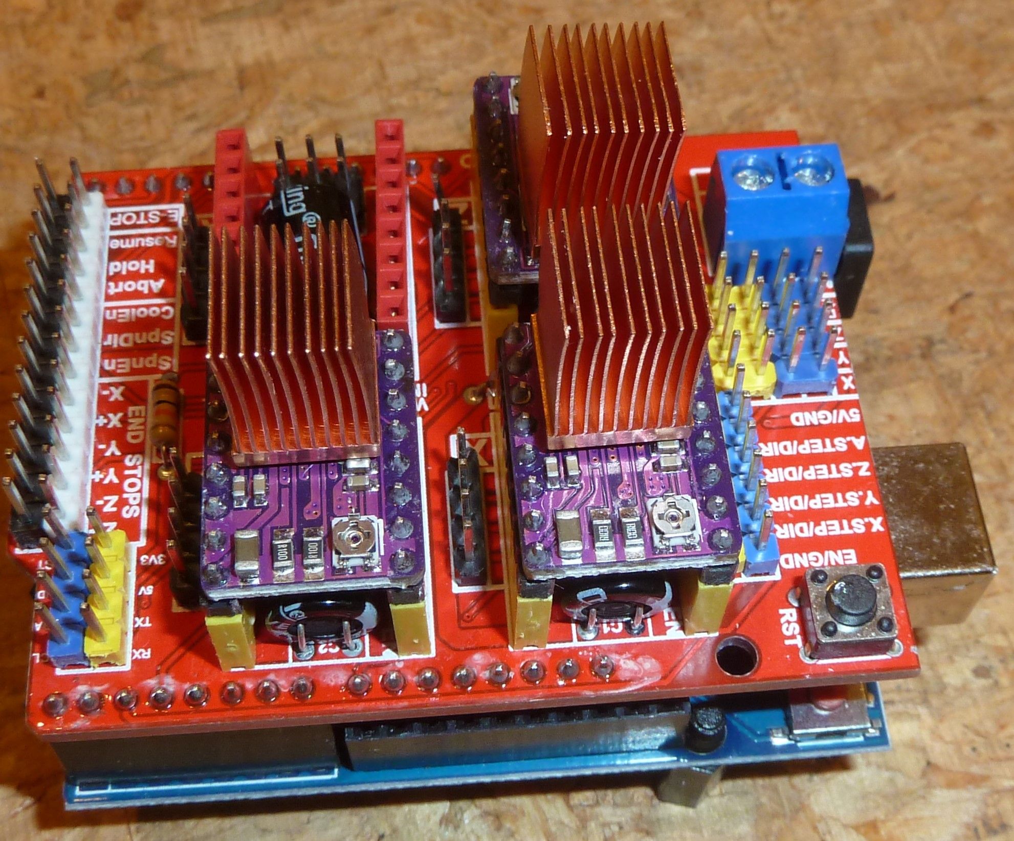
It makes for a permanent attachment, but from what I've read, this should allow them to be driven at their maximum rated current without overheating. This way I'll at least have a glimpse of what it's like to run the steppers at 45v with 2.1a current before switching over to the 24v volt closed loop drivers. I'll let the epoxy fully cure overnight and then give them a test drive tomorrow. It might (?) even turn out that with the extra power I don't even need the closed loop drivers. We'll see.I loaded GRBL 1.1h onto the arduino. Doing so is a very simple and quick process: just copy the GRBL library over to the arduino library folder and then compile and upload the uploadGRBL example program that comes with it. That's all there is to it. From there the default settings can be customized if so desired. I'll probably be testing different speed and acceleration settings.
-
@NeverDie Not surprisingly, some people are already doing laser ablation of soldermask, and the results are pretty good!
Lasering out PCB Solder Mask in ChiliPeppr – 07:39
— John Lauer@NeverDie said in CNC PCB milling:
@NeverDie Not surprisingly, some people are already doing laser ablation of soldermask, and the results are pretty good!
Lasering out PCB Solder Mask in ChiliPeppr – 07:39
— John LauerI tried shopping for lasers last night, but it's not straight forward. The variables seem be: power, wavelength, focal distance, optics, size of dot, and sharpness of dot. Unfortunately, lasers don't seem to be marketed that way. Instead, the listings seem to assume you can infer that.
Apparently single mode lasers would be better for this application because they produce better defined dots, but that's the only tidbit of useful information I've so far gleaned. If anyone here with laser experience can make a recommendation for a CNC mountable laser to ablate solder mask, that would be great. Also, is it better to steer the beam by moving the laser around on the CNC as though it were and endmill, or is it better to get a laser with moveable mirrors to direct the beam where it should go? I'm guessing that treating it like an endmill would be the more plug-and-play of the two options, where you simply turn on the laser whenever the z-axis gcode implies the z-axis is below zero, and turn it off when the gcode implies the z-axis would be above zero. -
@NeverDie said in CNC PCB milling:
@NeverDie Not surprisingly, some people are already doing laser ablation of soldermask, and the results are pretty good!
Lasering out PCB Solder Mask in ChiliPeppr – 07:39
— John LauerI tried shopping for lasers last night, but it's not straight forward. The variables seem be: power, wavelength, focal distance, optics, size of dot, and sharpness of dot. Unfortunately, lasers don't seem to be marketed that way. Instead, the listings seem to assume you can infer that.
Apparently single mode lasers would be better for this application because they produce better defined dots, but that's the only tidbit of useful information I've so far gleaned. If anyone here with laser experience can make a recommendation for a CNC mountable laser to ablate solder mask, that would be great. Also, is it better to steer the beam by moving the laser around on the CNC as though it were and endmill, or is it better to get a laser with moveable mirrors to direct the beam where it should go? I'm guessing that treating it like an endmill would be the more plug-and-play of the two options, where you simply turn on the laser whenever the z-axis gcode implies the z-axis is below zero, and turn it off when the gcode implies the z-axis would be above zero.@NeverDie I could actually try this out.
I recently received solder mask paint, both white and green.
And I have a cheap 3 Chinese Watts uv laser engraver.
I was thinking that using transparent sheets is the easiest way to go since you have to expose it anyway, but ofcourse that also means more material use.
-
@NeverDie I could actually try this out.
I recently received solder mask paint, both white and green.
And I have a cheap 3 Chinese Watts uv laser engraver.
I was thinking that using transparent sheets is the easiest way to go since you have to expose it anyway, but ofcourse that also means more material use.
@Joerideman said in CNC PCB milling:
@NeverDie I could actually try this out.
I recently received solder mask paint, both white and green.
And I have a cheap UV laser engraver.
That would be great!
-
@NeverDie said in CNC PCB milling:
I suppose the GRBL capacitor rating may soon be a moot issue anyway, as the servo42A closed loop driver accepts an input voltage of only 12-24v, and, not surprisingly, it appears to have its own back EMF cap on its driverboard:

The original mechaduino v0.2 accepted up to 35v:
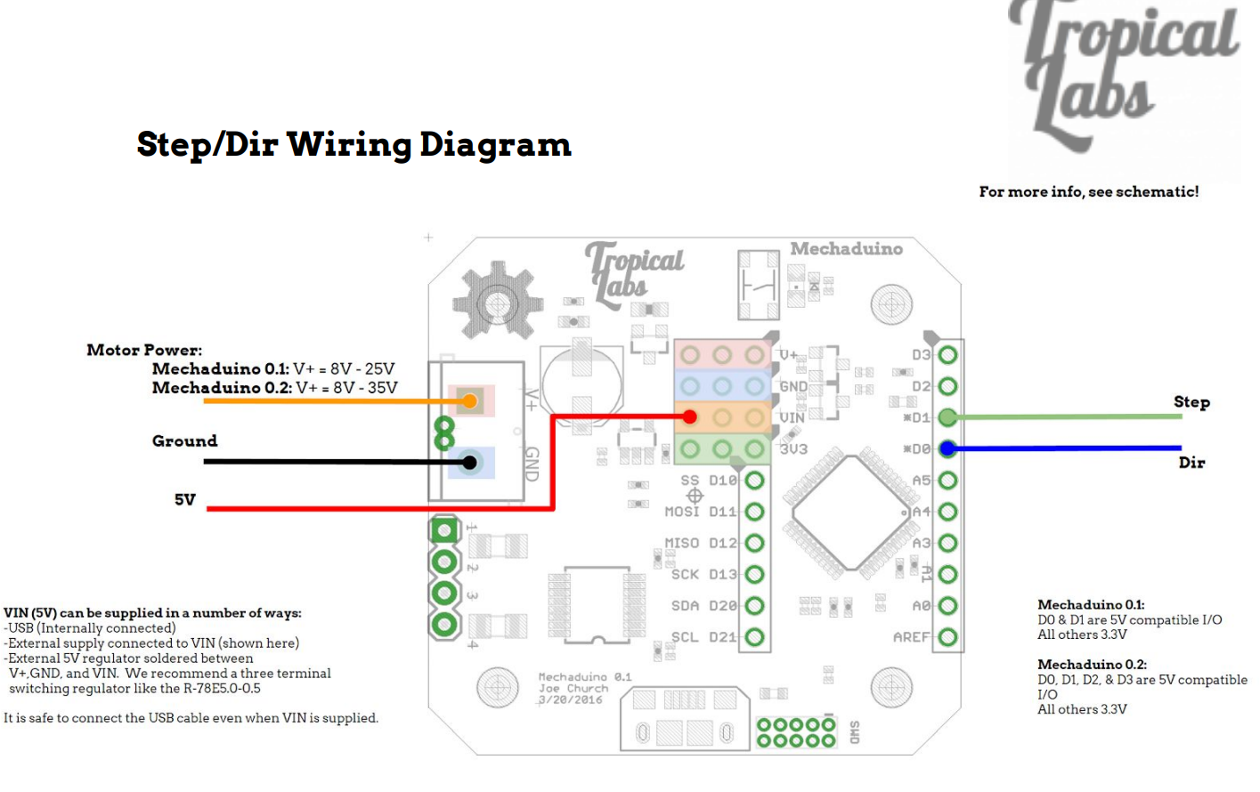
So, because the clone that I purchased allows for only 24v input, it's an unfortunate downgrade from the original. :(
@NeverDie said in CNC PCB milling:
@NeverDie said in CNC PCB milling:
I suppose the GRBL capacitor rating may soon be a moot issue anyway, as the servo42A closed loop driver accepts an input voltage of only 12-24v, and, not surprisingly, it appears to have its own back EMF cap on its driverboard:
The original mechaduino v0.2 accepted up to 35v:
So, because the clone that I purchased allows for only 24v input, it's an unfortunate downgrade from the original. :(
Reporting back: it turns out the voltage issue is moot. After playing around with a NEMA 17 and a DRV8255 driver, it turns out the NEMA 17 doesn't behave well at higher voltages anyway. At the higher voltages it's prone to resonating and not even turning. Also, unlike the original NEMA 17's, the "upgraded" NEMA 17's don't seem to perform well at 12v either. Rather, 24v seems to be more or less the sweet spot, and at a current that's around a little more half its rated maximum. So that was quite a surprise, at least to me. Also, even with the copper finned heatsinks, and the reduced voltages and currents, the DRV8255's get quite hot! If I'm going to run the upgraded steppers from stepsticks, I think I'm probably going to need to fan cooling in addition to the heatsinks. I wonder if I'll have to add some kind of heatsinks and fan cooling to the closed loop steppers as well?
I guess, if need be, I could either "downgrade" back to the original, smaller NEMA 17's that came with the kit, or else upgrade to TMC5160's (which run cooler) to better support the higher torque "upgraded" NEMA 17's. In the worst case I would shift to the standalone drivers discussed earlier, each of which comes with massive heatsinks.
All that said, the present currents are fairly paltry compared to what NEMA 23's consume. I imagine NEMA 23 drivers get very hot indeed!
Lastly, but importantly, I think I maybe see why my setup is loosing positioning when I jog around manually. Basically, by default GRBL turns off the drivers almost completely at the end of a command rather than maintaining holding torque on them. I'm guessing that may allow some slippage to happen that shouldn't happen during those relaxation periods. It has me curious now as to whether this might also happen while running a lengthy grbl script--maybe during periods when the z-height is locked and not otherwise changing? I guess I'll have to run some tests to find out. I find it hard to believe that GRBL might make a bonehead mistake like that, but.... maybe? Regardless, this would be something that the closed loop drivers could correct for, because their magnetic encoders have quite good resolution. :-) Based on tracking info, I'm pretty sure I'll be receiving them this week.
-
I never imagined that I would burn out four (4) DRV8825 stepper drivers and two (2) arduinos in just a short stretch of time. Something about this GRBL design makes it ridiculously fragile. And, by the way, the fuse never blew! :stuck_out_tongue_winking_eye: It really might as well be a piece of wire for all the good it's doing. I'm just glad it didn't fry the computer I have connected to it.
Edit: Good heavens! Here's a similar board, and beware! It's absolutely riddled with fatal flaws:
Worst CNC shield 12v /24 volt board GRBL v4 Arduino Nano (Problems, fix, Mods, flaws, corrections) – 10:16
— MangoJelly Solutions for FreeCAD