CNC PCB milling
-
@NeverDie ah, ok, nevermind. Too many part numbers and bit references in a single post for my peanut brain :grimacing:
@Yveaux said in CNC PCB milling:
@NeverDie ah, ok, nevermind. Too many part numbers and bit references in a single post for my peanut brain :grimacing:
Don't feel bad. Unlike me, you still have your money! I had assumed that because the MKS SERVO42A appeared to be a rip-off of the mechaduino design that they had copied the BOM as well. Instead, they made it worse. If it hadn't found the rant I linked to above, it might have taken me a long-time to realize the difference.
Edit: I just now ordered a uStepper S, which is the 16 bit version. Coming from Denmark with Danish postal shipping (the only option) it may take a couple of weeks to get here. Unless I'm mistaken, it is the highest resolution closed-loop stepper driver+encoder combination currently on the market (well, excluding whatever big ticket industrial solutions may exist). Is it overkill given the other sources of slop in my existing rig? Maybe. I would guess so, but right now I don't have a quantified grasp of just how good or bad the other system components are performing, so I can't really say with any certainty.
Edit: I looked into the possiblity of desoldering the 12-bit encoder on the MKS servo42A and then soldering on the original 14 bit magnetic encoder in it place. Unfortunately, the pinout is different, so that's not a practical option. Looking back, it would have been better to build a mechaduino from scratch using the open source files and thereby completely remove slip-shod aliexpress profiteers from the equation. Lesson learned! It's much harder to rely even on reviews anymore, since many of those now seem to be infiltrated by the marketers. Even on amazon. These days it has become a serious obstacle to making an informed purchase decision.
-
Does anyone here know how to invert (take the negative) of a gerber image? Because it's open source, I'd like to order some extra uStepperS boards (it would be much faster than ordering a fully populated board from Denmark), but they used Altium Designer, which inverts the ground plane:
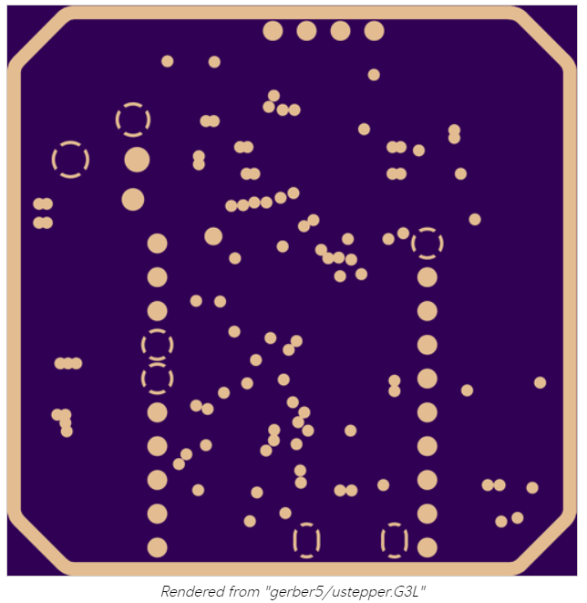
If I were to submit this to a fab, it would come out wrong.In theory, if I were to change the layer to a "signal" layer instead of a "plane" layer, it would be correct. I tried that, but in this case doing that erases the contents of the layer, so that's no good as an after-the-fact solution.
I tried looking for a gerber editor that could do this, but I only found one, and despite it promising "download now", all it did was collect my information and provided no download.
Anyone? Bueller? Anyone?
-
I figure full 14-bit resolution of absolute position will be enough, and that's what the AS5048A promises: https://www.mouser.com/datasheet/2/588/AS5048_DS000298_4-00-1100510.pdf That's 0.0219 of a degree resolution.
As near as I can tell, the AS5047D that the mechaduino chose instead delivered much less than that. According to the datasheet it had " a maximum resolution of 2000 steps / 500 pulses per
revolution." I'm not entirely sure what that means in this context, because in the paragraph just before that it says, "A standard 4-wire SPI serial interface allows a host microcontroller to read 14-bit absolute angle position data
from the AS5047D," which makes it sound as thought 14 bit resolution should have been achievable, but apparently it wasn't. https://www.mouser.com/datasheet/2/588/AS5047D_DS000394_2-00-1513297.pdfIn the case of the AS5048A, however, whatever ambiguity that clouded the AS5047D datasheet has been lifted, because according to https://ams.com/as5048a the AS5048A is capable of 16384 positions per revolution, and it doesn't discuss "steps" at all.
Interestingly, this chip has been on the market for quite a while and so there are a number of github libraries for it. It is protected by a patent filed in 2005 in Europe and 2006 in the US (US Patent 7,095,228).
-
@Renzo-Mischianti Thanks for your post. Looks like you've been quite a busy bee. ;-)
Have you had any success with solder mask?@NeverDie I use this steps, and I'm quite satisfied
https://www.mischianti.org/2019/03/14/design-and-mill-pcb-easy-and-cheap-part-5/
Nothing special, but works correctly..
-
It highly depends on the lead/ball screws, if the tolerances are in range of 0.01mm and backlash at about 0.1mm a 0.X deg of resolution at the steppers/servos doesn't matter since a normal lead screw is 4-8mm/turn.
Even 200 full steps/rev (1.8 deg stepper and full steps) with 4mm/rev screw means 50 full steps/mm or 20 micron/step (0.02mm/step) linear resolution which is much better compared to the rest tolerances of the machine.
On high precision rails, very tightly built machine it might make a difference, but for these cheap routers it doesn't.LE. @NeverDie 0.27 deg error translates to 0.003mm linear error (3 microns) assuming 4mm/rev screws are being used. Do you think you can notice/measure that? (4mm/360)*0.27=0.003 Even if using HUGE 16mm/rev ball screws translates to 0.012mm of error, unnoticeable.
-
Hey @NeverDie, everyone,
It is good to see how this thread developed over the time and you guys are enjoying the PCB milling.
Unfortunately I had many other responsibilities and was super busy, so a lot from my projects had to be postponed. Nevertheless I'm still working with my CNC.A few days ago I replaced the spindle to a laser module to make same plywood engraving, and the original spindle motor holder (the 3D printed stuff) broke during the unscrew...
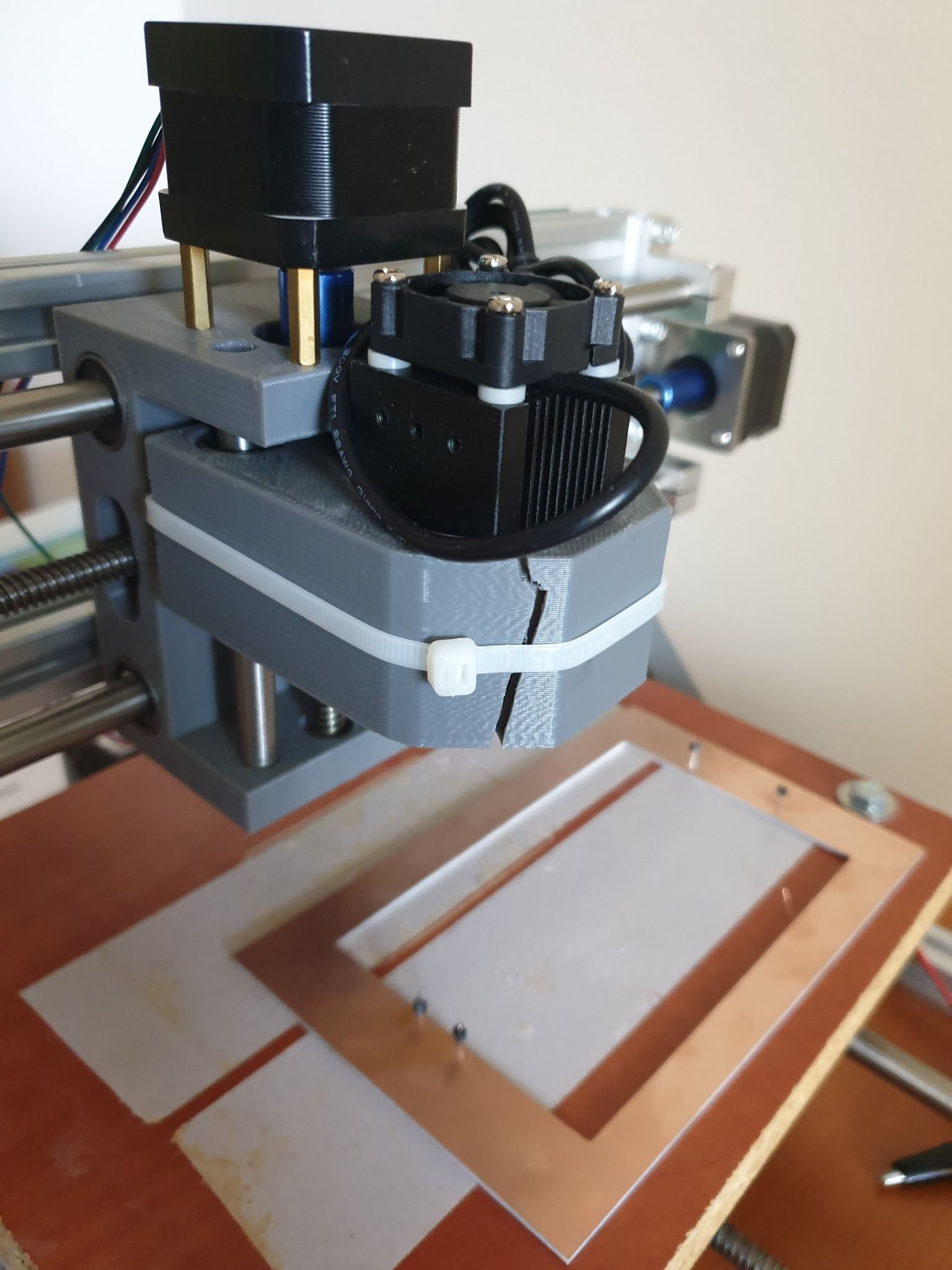
I managed to fix the laser module with cable tie. :)
It is ok for the laser, but of course not for the spindle and for the PCB milling.
Replacement parts are available mostly in packages (e.g. https://www.ebay.com/itm/Replacement-Parts-DIY-Kit-for-CNC-1610-2418-3018-Spindle-Holder-Screw-Polish-Pod/112382449851), but it is possible to print your own version too.
Some guys already came up with an enhanced design, such as https://www.thingiverse.com/thing:3586273I already wanted to make an upgrade on the CNC, so I came to a conclusion, that I will fix the broken part with a custom 3D printed one, then sell the machine.
I already ordered my new toy, a CNC3020T (EUR 325 + shipping EUR 25):
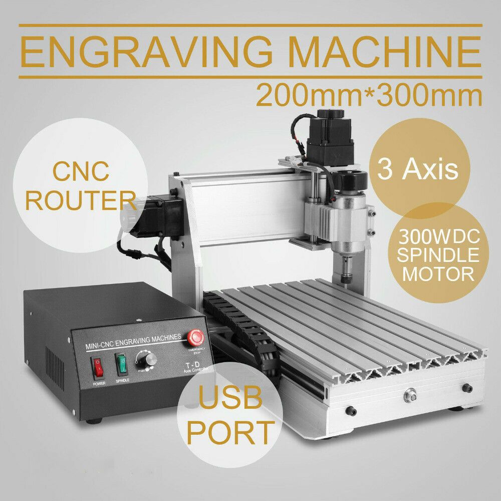
Well, I hesitated a lot and almost bought a CNC3040Z-DQ (bigger, better, ball screw), but as currently I really don't have enough space for it (and to be honest, no reason to buy a better/bigger) I sticked with the 3020T. The quality I achieved with my 2418 will be definitely reproducible and this is enough.
I just read the endmill isolation routing posts. Interesting stuff.
I'm curious whether you can use smaller ones to deal with the 6mil/6mil trace/isolation sizes.Happy milling and cheers!
-
It highly depends on the lead/ball screws, if the tolerances are in range of 0.01mm and backlash at about 0.1mm a 0.X deg of resolution at the steppers/servos doesn't matter since a normal lead screw is 4-8mm/turn.
Even 200 full steps/rev (1.8 deg stepper and full steps) with 4mm/rev screw means 50 full steps/mm or 20 micron/step (0.02mm/step) linear resolution which is much better compared to the rest tolerances of the machine.
On high precision rails, very tightly built machine it might make a difference, but for these cheap routers it doesn't.LE. @NeverDie 0.27 deg error translates to 0.003mm linear error (3 microns) assuming 4mm/rev screws are being used. Do you think you can notice/measure that? (4mm/360)*0.27=0.003 Even if using HUGE 16mm/rev ball screws translates to 0.012mm of error, unnoticeable.
@executivul That's how I previously looked at it, but now I'm looking at it as: total error = sum of individual errors. Previously, for any particular fix I could talk myself out of it by an argument such as the one you articulated. However, even though the individual errors may be small, they may sum up to something bigger that is noticeable. So, this is the first of what I hope will be at least a few refinements, and the hope is that the sum of the refinements will make a difference even if not much is improved by any one of them.
I'm not sure what to do about "following error" though other than to move more slowly. All machines have it to one degree or another. I think everyone who has closed-loop becomes aware of it very quickly because it suddenly becomes so easy to track. I suppose more powerful motors and faster acceleration would help, but ultimately I think maybe better motion planning and control influenced by closed-loop feedback is what's needed. However, I'm not sure if that technology even exists yet. Maybe somewhere in LinuxCNC or something like that? Ultimately, maybe what's needed is closed-loop DRO feedback. The hardware isn't cheap, and figuring out how to retrofit it on to an existing system looks to be challenging. Still, it might be worth it. High quality Industrial grade CNC machines all seem have it.
And what about software backlash compensation? How well does that work? I'm thinking that with DRO monitoring that would be a lot easier to dial in. One thing helps another.
-
I cured some uv solder mask using the roller method. As a result of that experience I'm going to change over to a UV light that doesn't have a bottom. That way I won't disturb the work by picking up the wet film stack and moving it into under the UV light to cure. Instead, without moving the wet film stack, I'll simply position the UV light over the stack and turn it on.
I can now confirm that polypropylene does a very good job of not sticking to the solder mask.
Thickness on my solder mask came out uneven, but maybe that will improve with further experience. I put a 1/4" piece of glass over the wet film stack before rolling it, so I'm not sure where the waviness in thickness came from, except maybe from me disturbing the stack while relocating it to be under the UV light.
I found a 3 mil drawdown bar and a 4 mil drawdown bar, so after the new UV light source arrives I'll have a try at laying down the solder mask wet film using those.
I'm actually getting two new UV light sources, as I'm not sure which I will prefer. One uses UV tubes (which it claims emits at 365nm) and which gets rave reviews on amazon from people who are using it to cure uv resins:
https://www.amazon.com/gp/product/B012MEZP2E/ref=ppx_yo_dt_b_asin_title_o03_s00?ie=UTF8&psc=1
The downside is that the uv tubes reportedly burn out after a while and need to be replaced.The other is just a larger UV LED nail dryer, like the one I tried last night, except that it has no bottom, as I discuss just above:
https://www.amazon.com/gp/product/B07MC4CZS1/ref=ppx_yo_dt_b_asin_title_o02_s00?ie=UTF8&psc=1 -
I cured some uv solder mask using the roller method. As a result of that experience I'm going to change over to a UV light that doesn't have a bottom. That way I won't disturb the work by picking up the wet film stack and moving it into under the UV light to cure. Instead, without moving the wet film stack, I'll simply position the UV light over the stack and turn it on.
I can now confirm that polypropylene does a very good job of not sticking to the solder mask.
Thickness on my solder mask came out uneven, but maybe that will improve with further experience. I put a 1/4" piece of glass over the wet film stack before rolling it, so I'm not sure where the waviness in thickness came from, except maybe from me disturbing the stack while relocating it to be under the UV light.
I found a 3 mil drawdown bar and a 4 mil drawdown bar, so after the new UV light source arrives I'll have a try at laying down the solder mask wet film using those.
I'm actually getting two new UV light sources, as I'm not sure which I will prefer. One uses UV tubes (which it claims emits at 365nm) and which gets rave reviews on amazon from people who are using it to cure uv resins:
https://www.amazon.com/gp/product/B012MEZP2E/ref=ppx_yo_dt_b_asin_title_o03_s00?ie=UTF8&psc=1
The downside is that the uv tubes reportedly burn out after a while and need to be replaced.The other is just a larger UV LED nail dryer, like the one I tried last night, except that it has no bottom, as I discuss just above:
https://www.amazon.com/gp/product/B07MC4CZS1/ref=ppx_yo_dt_b_asin_title_o02_s00?ie=UTF8&psc=1Years ago I bought a face tanning device. They still sell these things second hand. And I expect like a lot of convenient but time consuming beauty devices, they are hardly used.
Cost you 5-10 euros here in the Netherlands. You might have something similar.
Anyway 30 seconds with this thing and it's cured.
-
An idea discusssed on Hackaday is to remove the UV filter on a personal pocket projector and then use the projector to project a solder mask image directly onto the solder mask of a PCB. If it can be made to work, this seems fairly elegant to me.
I hadn't realized that personal pocket projectors had become so affordable. You can buy a new 1080p pocket projector on ebay for as little as $30-$50.
A different Hackaday project uses Kapton tape cut by computer to somehow make a one-off solder mask for prototyping prototyping purposes.. Whatever works!
-
@NeverDie I just read back around 2017.
Have you ever managed to get Andrews result? He claimed 6mil back then.
@Joerideman said in CNC PCB milling:
@NeverDie I just read back around 2017.
Have you ever managed to get Andrews result? He claimed 6mil back then.
Not consistently. That's why I'm doing a new round of improvements now. Somehow it's always the last little bit that consumes the largest share of the effort.
-
@NeverDie my UV lamp is made from a UV led strip glued to a cardboard box, I just place the UV over the board not the board in the lamp.
The so called 1080p cheap projectors are actually 640x480 real resolution, or even 320x240, they are able to accept a 1080p signal and scale it down so are falsely advertised as FullHD. That was the state of things a year ago when I last checked. Much better to get a sh brand projector instead.
About resolution: FullHD 1920x1080 over a 150x100mm board gets you 10pixels/mm roughly, that is 0.1mm resolution, I don't know if that is good enough, also focusing at such a close range would require some lens hacking, from the factory they focus at 50cm at least and get you a 60-100cm diagonal size. -
@NeverDie said in CNC PCB milling:
You probably want to aim for a thickness above the copper of about 0.5mm
Correction: I should have said 0.5 mils.
That's according to altium: https://resources.altium.com/p/how-choose-correct-solder-mask-your-pcb#:~:text=The typical solder mask thickness,solder mask over your traces.
However, I'm not sure if they're referring to wet film thickness or dry film thickness. I guess with uv cured paint it maybe would be the same either way?
@NeverDie said in CNC PCB milling:
@NeverDie said in CNC PCB milling:
You probably want to aim for a thickness above the copper of about 0.5mm
Correction: I should have said 0.5 mils.
That's according to altium: https://resources.altium.com/p/how-choose-correct-solder-mask-your-pcb#:~:text=The typical solder mask thickness,solder mask over your traces.
However, I'm not sure if they're referring to wet film thickness or dry film thickness. I guess with uv cured paint it maybe would be the same either way?
I found that certain brands of Kapton tape are advertised to be 0.5 mils thick: https://smile.amazon.com/gp/product/B00EP254UU/ref=ppx_yo_dt_b_asin_title_o00_s00?ie=UTF8&psc=1
I've ordered some and will try using that to set the film thickness of the solder mask when I flatten it out between two very flat 1/2" thick panes of glass.
-
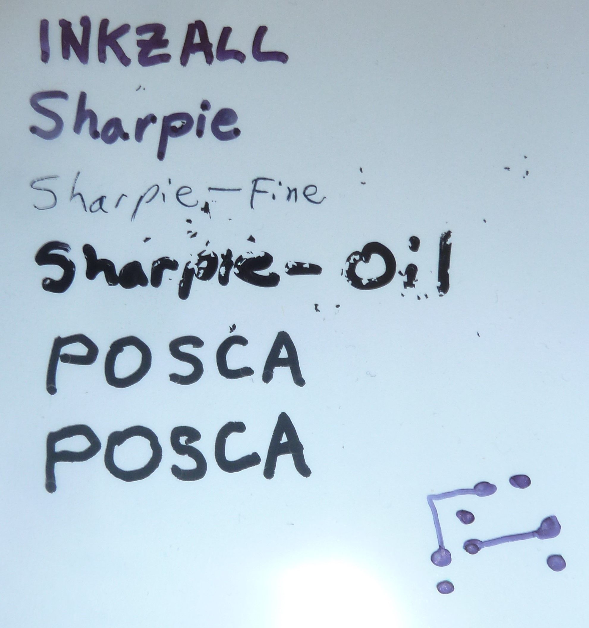
For purposes of solder masking, I compared a number of black markers for drawing on PP sheeting to see which would be the blackest and most opaque. I compared: Inkzall, regular Sharpie, Sharpie Oil, and POSCA (a Japanese paint pen). By reputation I had thought the POSCA would win, but by far the blackest and most opaque of the bunch was the Sharpie Oil. It appeared to be genuinely opaque. The Inkzall and the regular sharpie were not opaque at all.
-
For purposes of solder masking, I compared a number of black markers for drawing on PP sheeting to see which would be the blackest and most opaque. I compared: Inkzall, regular Sharpie, Sharpie Oil, and POSCA (a Japanese paint pen). By reputation I had thought the POSCA would win, but by far the blackest and most opaque of the bunch was the Sharpie Oil. It appeared to be genuinely opaque. The Inkzall and the regular sharpie were not opaque at all.
Reporting back: After letting it dry overnight, I discovered that the Sharpie-Oil apparently shrinks and then flakes off of the PP film:
Not sure if it behaves better with other films or not.
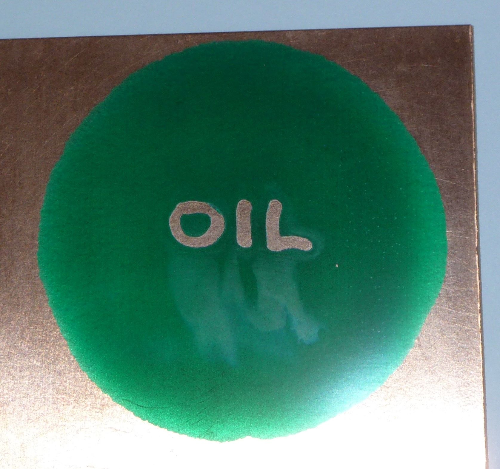
However, before it dries, it performs great, as seen below.
Here I am squishing solder mask between two thick sheets of glass:
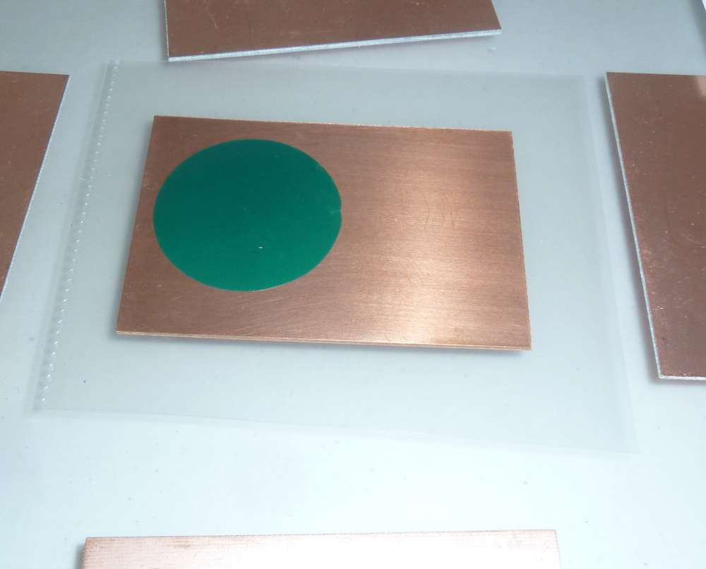
This technique seems to do a reasonably good job of producing a uniform thickness of the UV solder mask.Here I use a Sharpie Oil marker to print the word OIL and place it over the flattened solder mask before exposure to UV:
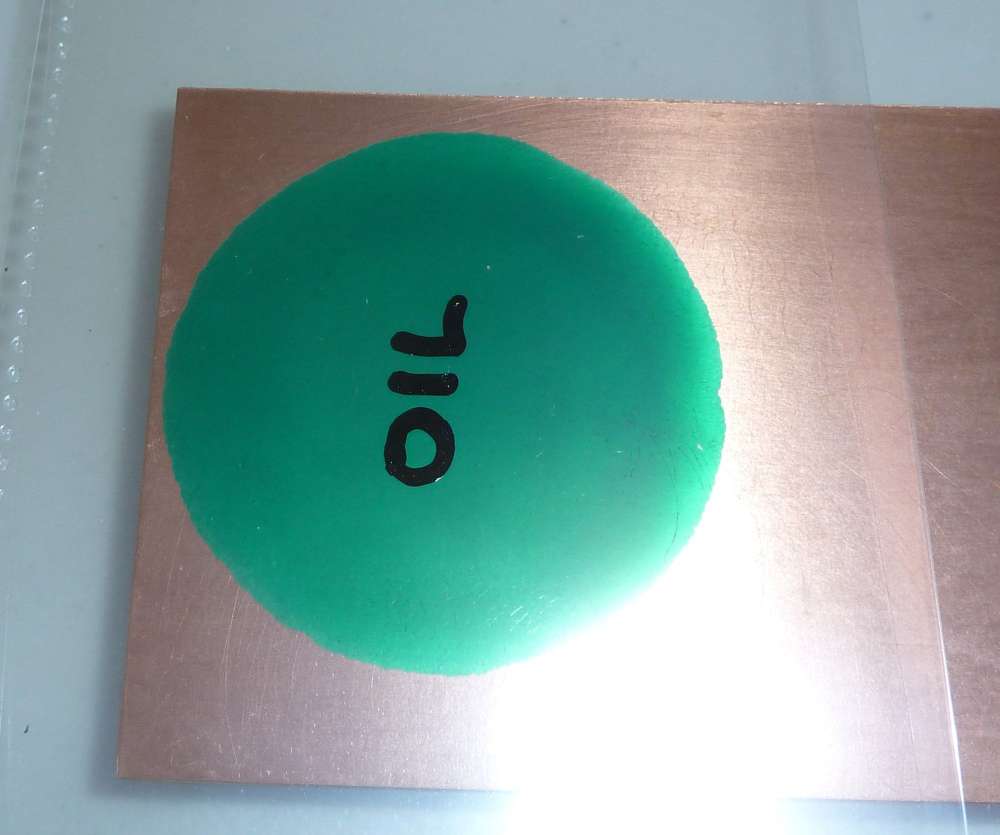
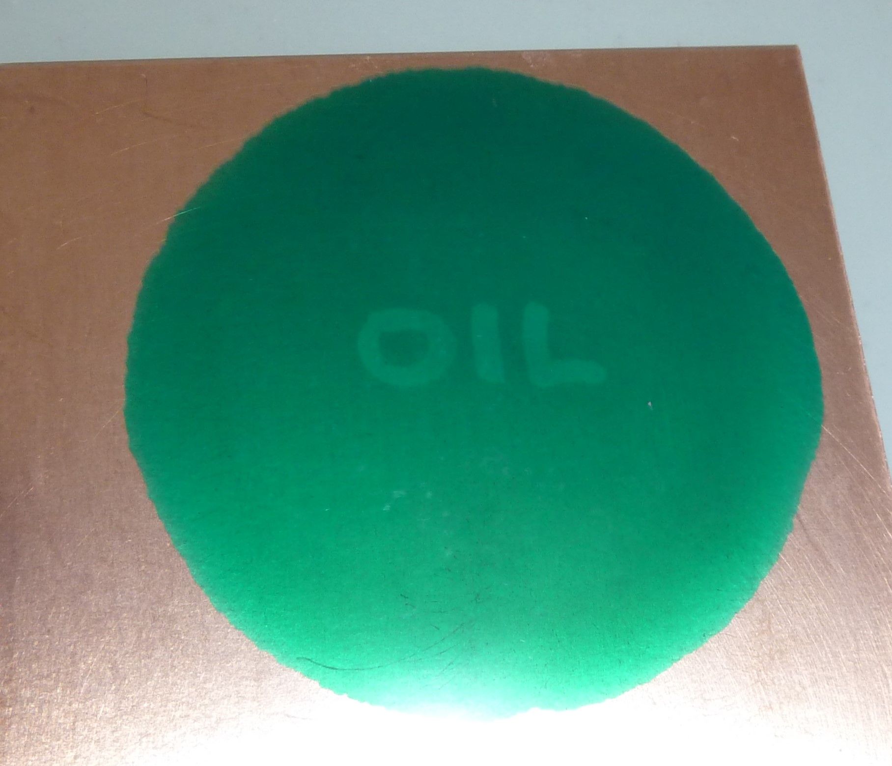
I exposed it to UV for a full 99 seconds, which may have completely cured the non-masked solder-mask. Here is how it looks after I removed the "OIL" mask:
Here is how it looks after peeling back the top layer of PP film:
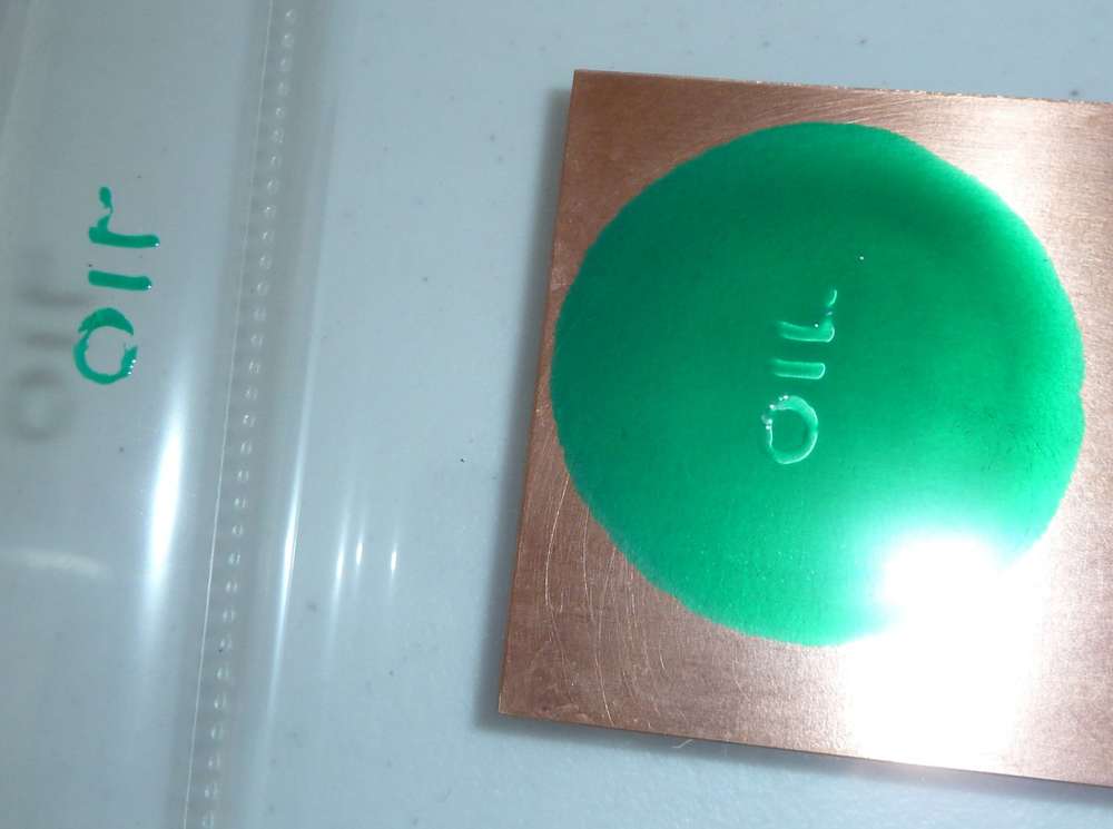
I then removed the uncured solder mask using IPA, after which I cured it some more under UV just to be sure:
As a first attempt, not bad! Using a high opacity mask probably helped quite a bit.
So, I guess now the question is: which inkjet ink/pigment or which laserjet toner has the highest opacity? For instance, there is this which claims to be: https://www.amazon.com/Ink-Dynasty-Resistant-Refillable-cartridge/dp/B00E3PAUXA
or this:
https://www.screenerschoice.com/index.php?route=product/product&product_id=157From the looks of it, the answer will be some kind of inkjet black pigment, which is consistent with the results I got from comparing ink pens vs paint pens above.
-
Reporting back: After letting it dry overnight, I discovered that the Sharpie-Oil apparently shrinks and then flakes off of the PP film:
Not sure if it behaves better with other films or not.
However, before it dries, it performs great, as seen below.
Here I am squishing solder mask between two thick sheets of glass:
This technique seems to do a reasonably good job of producing a uniform thickness of the UV solder mask.Here I use a Sharpie Oil marker to print the word OIL and place it over the flattened solder mask before exposure to UV:
I exposed it to UV for a full 99 seconds, which may have completely cured the non-masked solder-mask. Here is how it looks after I removed the "OIL" mask:
Here is how it looks after peeling back the top layer of PP film:
I then removed the uncured solder mask using IPA, after which I cured it some more under UV just to be sure:
As a first attempt, not bad! Using a high opacity mask probably helped quite a bit.
So, I guess now the question is: which inkjet ink/pigment or which laserjet toner has the highest opacity? For instance, there is this which claims to be: https://www.amazon.com/Ink-Dynasty-Resistant-Refillable-cartridge/dp/B00E3PAUXA
or this:
https://www.screenerschoice.com/index.php?route=product/product&product_id=157From the looks of it, the answer will be some kind of inkjet black pigment, which is consistent with the results I got from comparing ink pens vs paint pens above.
@NeverDie I saw an YouTube video screenprinting. That guy noticed that semi transparent sheets work better than transparent sheets. Ink holds better or something.
I can actually try this one out. Because afteral. We want that 0.4mm pitch right?
I just need to find something to put the paint on.
-
@NeverDie I saw an YouTube video screenprinting. That guy noticed that semi transparent sheets work better than transparent sheets. Ink holds better or something.
I can actually try this one out. Because afteral. We want that 0.4mm pitch right?
I just need to find something to put the paint on.
@Joerideman said in CNC PCB milling:
@NeverDie I saw an YouTube video screenprinting. That guy noticed that semi transparent sheets work better than transparent sheets. Ink holds better or something.
I can actually try this one out. Because afteral. We want that 0.4mm pitch right?
I just need to find something to put the paint on.
Which thing are you planning to try? Sharpie-Oil on a semi-transparent sheet, or the uv resistant inkjet ink, or...?
For enhanced laser printing I found this: https://ikonartstencil.com/toner-enhancement-spray/
though I have no idea how well, or even if, it works. -
I received some Sharpie-Oil "Extra Fine" pens. Testing them, they have a 1mm line width, so they'd be no good for filling in features smaller than that. AFAIK, they have the smallest tips in the Sharpie-Oil series.
I received the 16-bit closed-loop uStepper hardware from Denmark, so I'll be testing that sometime soon. I intend to use it on the z-axis, since accuracy on depth of cut is critical. If even this is still not enough, then I'll work harder to identify the source of the error and, if appropriate, consider stronger measures like low run-out collets, low-runout bits, ball-screws, tighter linear rails and/or tracking absolute position with a DRO and/or possibly a different spindle.