CNC PCB milling
-
Reporting back: Regarding Sharpie-Oil pens, I found that it doesn't chip-off and disintegrate, even after letting it dry for a few days, if I write it onto inkjet transparency material instead of polypropylene:

Because it's so opaque, especially when compared to other black pens, it's the best pen I've found. The linewidth of the "Sharpie-Oil Extra Fine" pen is about 1mm, though, so that precludes using it in a plotter if ultra fine detail is required.
-
@NeverDie however.... The material sticks a bit to the paint.
@Joerideman said in CNC PCB milling:
@NeverDie however.... The material sticks a bit to the paint.
??? Which thing are you referring to?Right, so I still use the polyproylene against the solder mask, but I can layer this inkjet tranparency on top of that. It's an extra layer, but it's kept separate from the solder mask by the polypropylene layer underneath it. Is that what you mean?
-
@Joerideman said in CNC PCB milling:
@NeverDie however.... The material sticks a bit to the paint.
??? Which thing are you referring to?Right, so I still use the polyproylene against the solder mask, but I can layer this inkjet tranparency on top of that. It's an extra layer, but it's kept separate from the solder mask by the polypropylene layer underneath it. Is that what you mean?
@NeverDie yes.
-
I found a good "once and done" lubricant for my CNC called Krytox. It's made by Dupont, is non-toxic, never dries out, and is non-reactive with just about everything. It is more or less liquid teflon (PTFE). It comes in a wide spectrum of different viscosities. I'm using GPL105, but I think for a CNC one could argue for using a version that's a least slightly more viscous (i.e. GPL106 or higher).
There also exists grease versions of Krytox, so perhaps (?) that would be even better. In general, for any given lubricant, how does one decide what the right viscosity is to use?
@NeverDie said in CNC PCB milling:
I found a good "once and done" lubricant for my CNC called Krytox. It's made by Dupont, is non-toxic, never dries out, and is non-reactive with just about everything. It is more or less liquid teflon (PTFE). It comes in a wide spectrum of different viscosities. I'm using GPL105, but I think for a CNC one could argue for using a version that's a least slightly more viscous (i.e. GPL106 or higher).
There also exists grease versions of Krytox, so perhaps (?) that would be even better. In general, for any given lubricant, how does one decide what the right viscosity is to use?
I guess maybe a dry lubricant would be a better choice, so that it doesn't attract dust or debris. To that end, I'm thinking maybe one of these:
https://smile.amazon.com/gp/product/B000GE1F9K/ref=ppx_yo_dt_b_asin_title_o00_s00?ie=UTF8&psc=1https://smile.amazon.com/gp/product/B00AF0ODGM/ref=ppx_yo_dt_b_asin_title_o01_s00?ie=UTF8&psc=1
Anyone have a preference, opinion, or other suggestions?
-
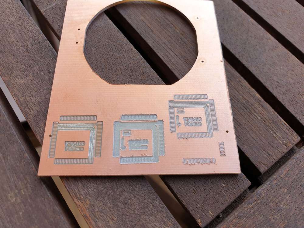
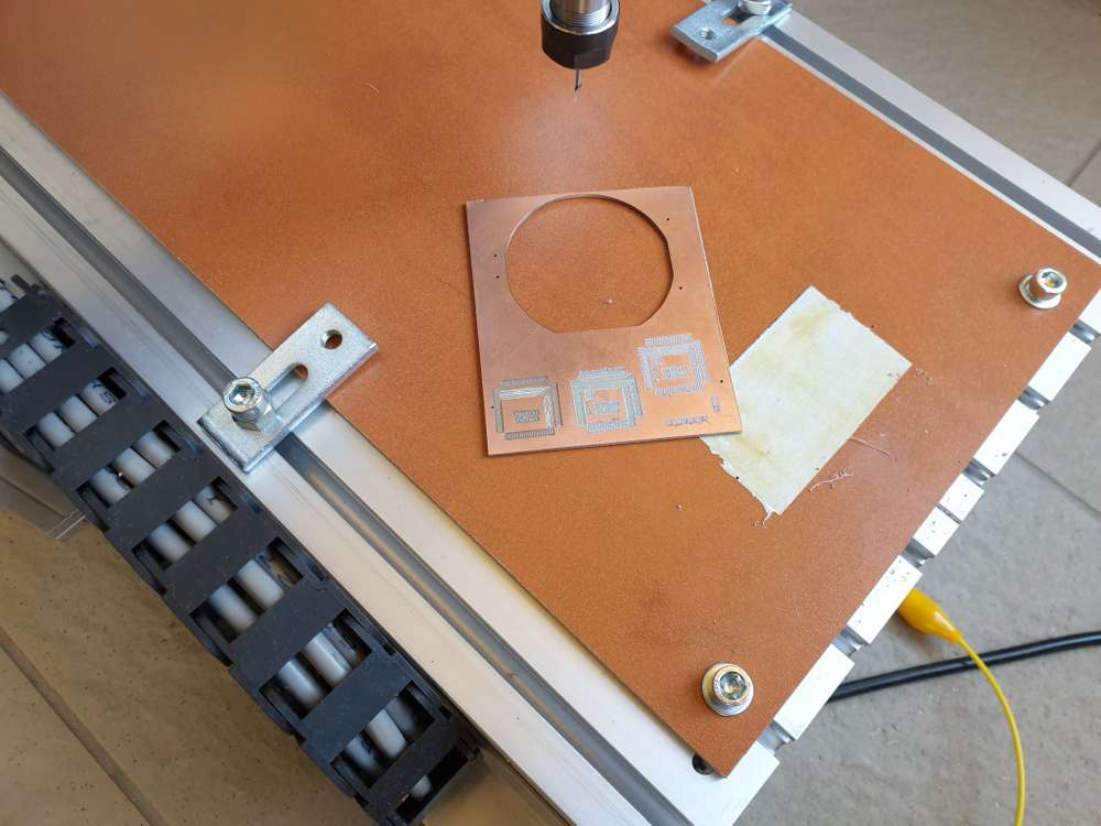
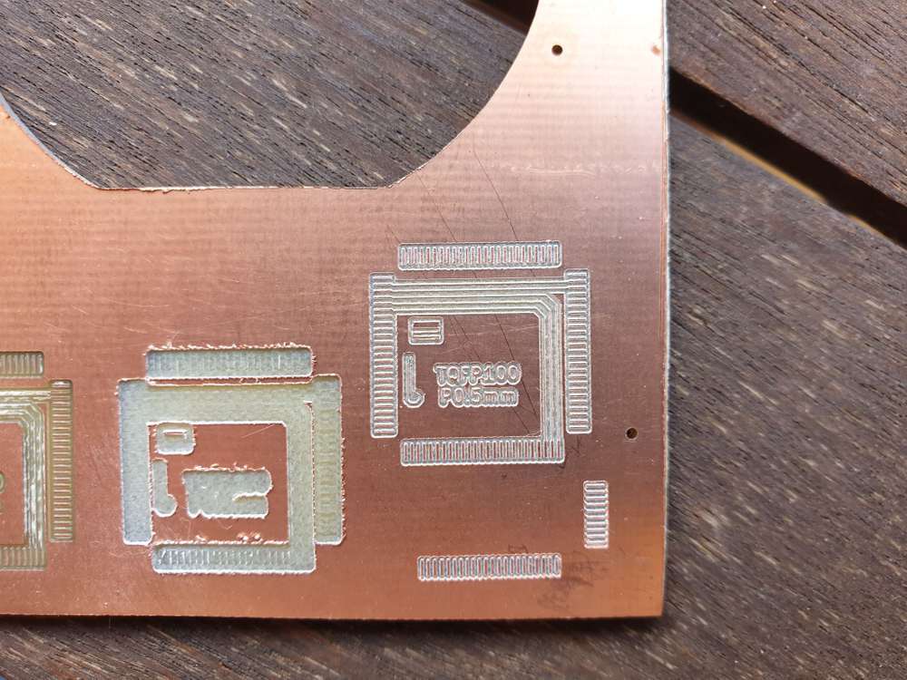
quick update, just managed to make some test milling.
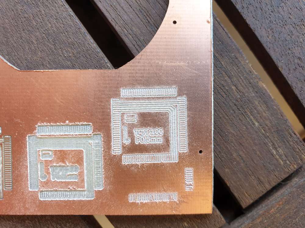
pro tip: always check your tip before milling :) I had to trash the one I used for the first two, as its end was chippedtraces are 6 mil, the footprint is tqfp100 p0.5, built in from kicad.
some of the the standalone traces are 6 mil with 6 mil clearance, their open end came up, but otherwise it looks ok.other 6 mil traces that are connected to pads are actually ok.
6mil traces where the clearance is 4 mil only were not millet at all, due to the isolation routing path made by flatcam.
overall, I'm happy with it.
I've also ordered a dial indicator measurement tool, I'll report the backlash and other measured precision details when it arrives.
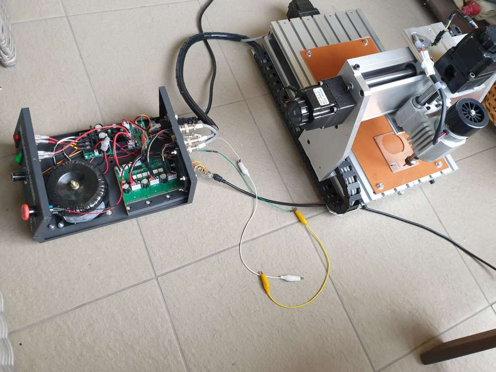
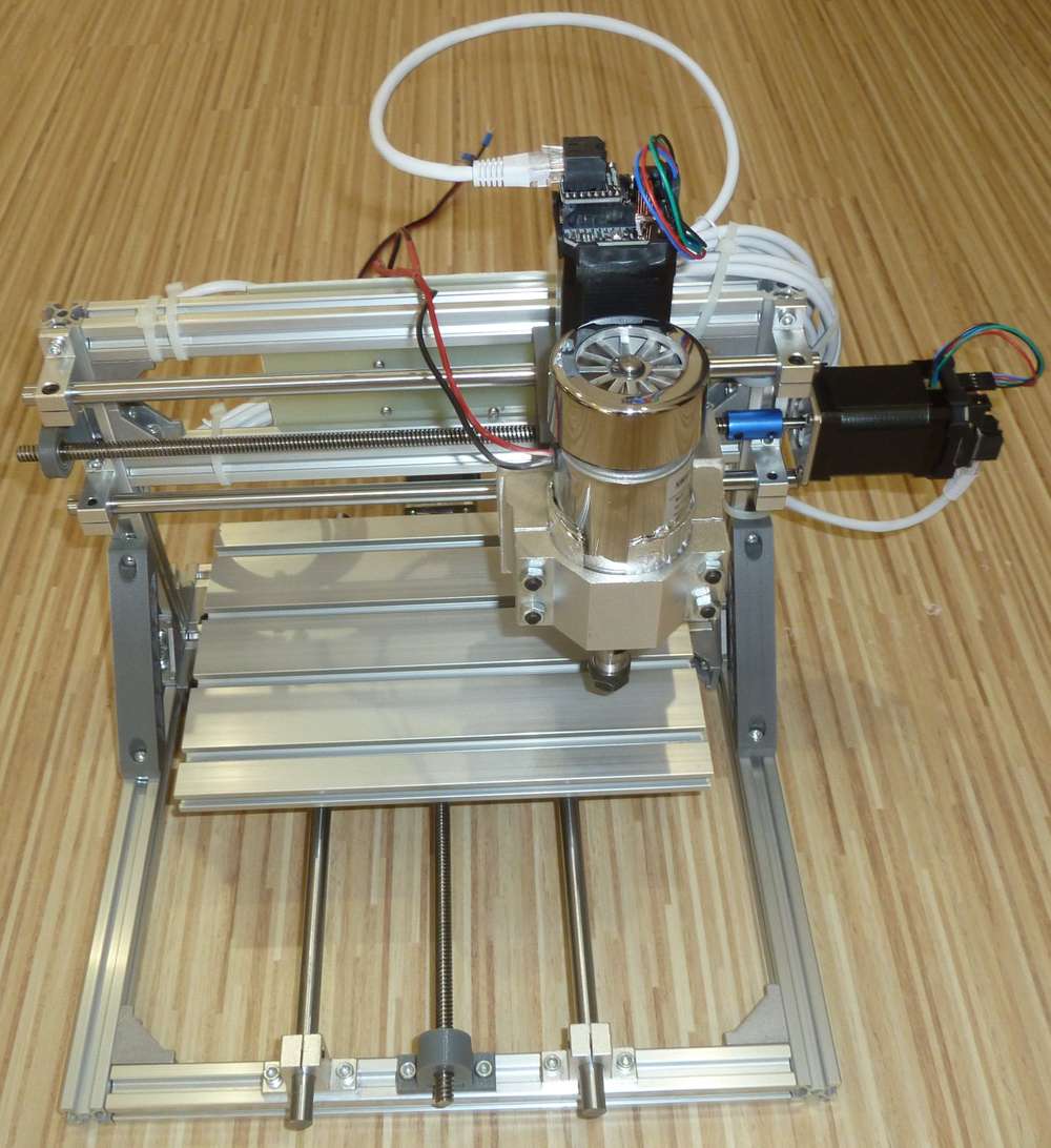
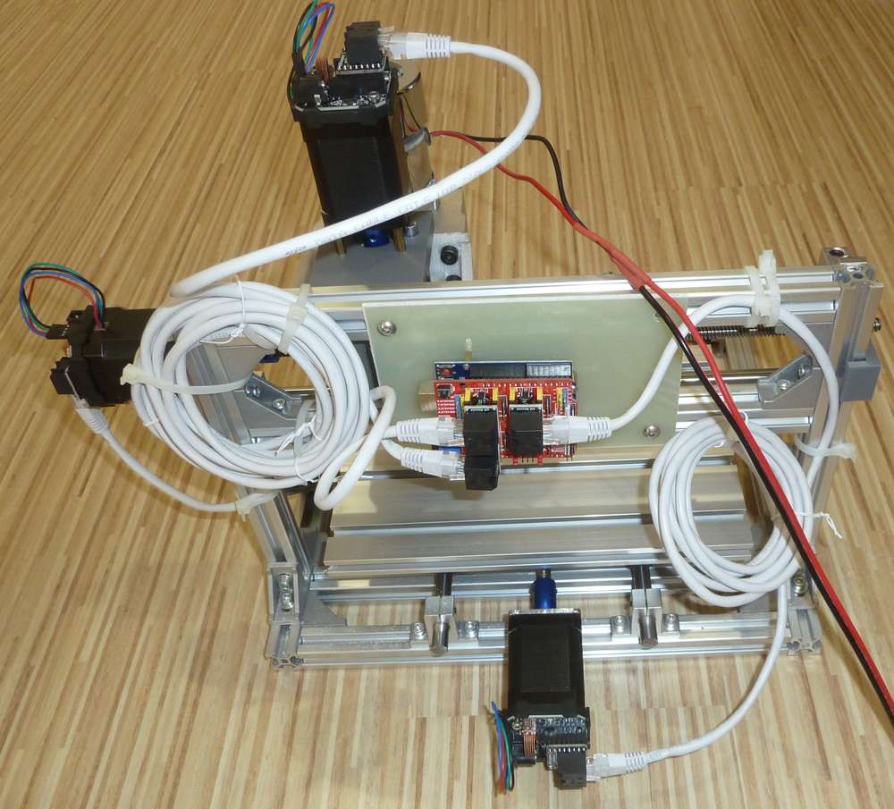
some pics:
the control box is open and it has an additional external grbl controller now, I'm working on a proper electronics.
-
quick update, just managed to make some test milling.
pro tip: always check your tip before milling :) I had to trash the one I used for the first two, as its end was chippedtraces are 6 mil, the footprint is tqfp100 p0.5, built in from kicad.
some of the the standalone traces are 6 mil with 6 mil clearance, their open end came up, but otherwise it looks ok.other 6 mil traces that are connected to pads are actually ok.
6mil traces where the clearance is 4 mil only were not millet at all, due to the isolation routing path made by flatcam.
overall, I'm happy with it.
I've also ordered a dial indicator measurement tool, I'll report the backlash and other measured precision details when it arrives.
some pics:
the control box is open and it has an additional external grbl controller now, I'm working on a proper electronics.
@andrew oh, for those who are interested, flatcam settings were the followings:
- tool dia: 0.1176326981
- passes: 2
- overlap: 0.15
- cut z: -0.05
- feed rate: 500
- spindle: 300 (0-1000 range, but in fact as the pwm signal is inverted now, it is equivalent with 700)
the engraving tip was 2001 (20degree, 0.1mm end)
-
quick update, just managed to make some test milling.
pro tip: always check your tip before milling :) I had to trash the one I used for the first two, as its end was chippedtraces are 6 mil, the footprint is tqfp100 p0.5, built in from kicad.
some of the the standalone traces are 6 mil with 6 mil clearance, their open end came up, but otherwise it looks ok.other 6 mil traces that are connected to pads are actually ok.
6mil traces where the clearance is 4 mil only were not millet at all, due to the isolation routing path made by flatcam.
overall, I'm happy with it.
I've also ordered a dial indicator measurement tool, I'll report the backlash and other measured precision details when it arrives.
some pics:
the control box is open and it has an additional external grbl controller now, I'm working on a proper electronics.
:clap: Nice! Thank you for the photos and for sharing your settings and early results.
@andrew said in CNC PCB milling:
I've also ordered a dial indicator measurement tool, I'll report the backlash and other measured precision details when it arrives.
:+1: I'm not sure how you would measure it, but I'd also be especially interested in how much "twist" potential there is on the z-axis, as it looks like a pretty long lever arm exists between the cutting bit and the x-axis linear bearings that are supporting it. On the other hand, maybe pre-tensioning from the sheer mass of the carriage and motors (spindle + z-axis stepper), together with a cutting depth of just 0.05mm and a small effective diameter for the cutting bit overwhelms any slop there, rendering it unimportant with respect to pcb milling. Seems that way, judging from your early evidence. I suppose all that weight might also eliminate z-axis backlash? Looking forward to that measurement.
As for me, I now have possession of the three closed-loop Ustepper-S drivers. I've installed them on the higher torque stepper upgrades and tested them electrically, and they all seem to work great. Now waiting on the dry lubricants to arrive before purging the old wet lubricants from the system (well, as much as I'm able to--the z-axis linear bearings were glued in-place on a previous carriage upgrade), and then I just need to re-assemble the CNC and mount the upgraded steppers on it. Lastly, I feel I need to add limit switches and an emergency kill-switch before powering up again, because with a closed-loop system, if the CNC ever overruns the end of a range, rather than merely slipping some steps like an open-loop system would, I'm pretty sure a pure closed-loop CNC will never give up trying to reach the unreachable and so keep grinding forever. Seems like some kind of simple time-out in the closed-loop code could notice lack of progress and prevent that. Or perhaps "virtual" endstops could be set using the uStepper-S position encoder. On the other hand, maybe just monitoring for excessive current draws on each stepper would be yet another way to protect, since it might protect the z-axis from a worst-case (Murphy's Law) scenario of overshooting (from bad g-code or otherwise) and burning its way deep into the spoilboard and beyond. Every now and then I see a youtube video where that actually happens to somebody, including all-hell-breaks-loose cases where the friction even lights the spoilboard on fire. Not as rare as you might think: many people on the MPCNC forum are afraid to leave their machine running unattended for even a few seconds. I found that out, to my surprise, after they were horrified when I showed them my LoRa device for remote monitoring my CNC for end-of-job completion. Rather than a convenience, literally all they could think about was a scenario like:
https://youtu.be/D2xoxPlDnW4(Yet another reason to switch to dry, non-oil lubricants. ;-) ).
Maybe the more advanced trinamic drivers can detect overcurrent? Surely yes, because they can implement homing without physical endstops. Meh, it might work, but without some experience with it I wouldn't trust it just yet to be bulletproof enough to rely on as a strong first defense. For now I guess limit switches will be both the easiest and most foolproof, and some kind of different/redundant protection can be added later for a more resilient failsafe.Anyhow, whatever it takes, I for sure want a CNC that can safely run unattended without the need for me to constantly watch over it, just as I don't feel the need to constantly watch my gas water heater or gas dryer whenever they operate. Thinking about it now, probably all that's needed would be a non-flamable spoilboard, because, if just milling a PCB, I'm pretty sure (?) nothing else on my CNC could catch fire, even in theory. Hmm.. What kind of non-flamable spoilboard material would best serve the purpose?
-
Just now came across something quite interesting. At time index 6:00, this youtube makes a compelling case for flipping upside down the spindle mount, so that the anti-backlash spring-nut is mounted on the bottom instead of the top of the z-axis carriage:
https://youtu.be/_qTjYUyNpGsJudging from his demonstration, this simple change may greatly reduce the amount of play.
Has anyone here tried 3D printing in metal? I've seen examples where you can do that, sinter it afterward, and then basically have a strong, useable metal part. If it works as advertised, maybe I could 3D print the carriage in metal for the next iteration.
-
I was reading the cnczone primer on ballscrews, and the closest scenario to PCB milling was:
Situation 5: "I am scratch-building a small CNC bench mill for machining casting waxes and light metal work. Accuracy is important. I am going to machine jewelry prototypes, small components for turbine engines and R/C, and other small parts with close tolerances."
Solution: This will require a very accurate and tight system with 0 backlash. As the size of the parts go down, the need for zero backlash and a quality fixed bearing set go way up. 0.005" of backlash would ruin a fine filligree in wax for gold casting, or a turbine diffuser. I'd go with C3 or better ground ballscrews, fine pitch, servomotors, direct drive, THK/NSK linear rails and trucks. A commercial bearing block would ensure success, or you can create blocks on your own, but they'll need to be well-made. You'll also need a fast, high-quality spindle, but that is another topic entirely.
I did a quick survey of ballscrews on ebay, aliexpress, and amazon, and all of the ones I randomly sampled were of type C7 quality, which is a much lower quality rating than the "C3 or better" type that's recommended in the quoted passage. That may throw a wrench into the idea of buying a pre-made inexpensive CNC if to get the required repeatability I need to subsequently rip out and replace a lot of key components with better quality ones. Since the better quality ballscrews are relatively expensive, and the quality type is never even mentioned in most CNC machine listings, I imagine they're probably of type C7 (or worse). To put numbers on it, the least expensive C3 ballscrew listed on aliexpress is $170:
https://www.aliexpress.com/i/32798741066.html
and nothing of type C0, C1, or C2 is even listed.That said, I do wonder whether a glass scale linear position sensor might allow a closed loop system to compensate using software. They're not hugely expensive, and they are commonly spec'd as accurate to 0.005mm, or 0.001mm for a modestly higher price. Since cutting depth is typically 0.05mm, I would think that either one should be good enough. I'm thinking that, at least for the z-axis, this might be worth exploring because for the z-axis all you typically need to do is reach the target depth-of-cut and then hold it there for relatively long time intervals while traces are cut, before picking up, moving to a new location, and repeating. I'm sure there are well studied algorithms for x and y as well, but z seems like it would be comparatively simple to implement. Well, actually, that's not entirely true, because the elevation map means the z-axis may need to continually adjust as well--maybe just not as quickly
Maybe what saves PCB milling is that part of the inaccuracy is related to distance travelled, and there's generally not much need for the z-axis to travel very far once the milling operation has begun (especially if the spoil board was milled flat beforehand by the same CNC). Maybe milling the copper cladding on a PCB flat prior to starting would be a feasible workaround that would throw the problem back into the idealized realm, so that then no elevation compensation would be needed. It might require thicker cladding to pull it off so as to avoid thinning it too much, but it just might work.
-
After doing a bit more reading, I think I'm on the right track as far as using a high precision linear gauge as the basis for the closed-feedback loop. There's a CNC manufacturer named accurateCNC which specializes in building CNC machines for milling PCB's, and as near as I can understand it, they take this approach and get good results with it: they use a linear guage that can resolve 0.1mm, and they claim 1 micron accuracy on their PCB milling: http://www.accuratecnc.com/designConsepts.php
Among other things, they also credit using the absolute best ballscews and a 60K RPM spindle that has negligible runout. As a result,All new models listed currently on our web site are extremely accurate. The absolute accuracy is definitely 8 to 10 TIMES better than the competitors
If that is so, then I presume their machines literally are the state-of-the-art.
I think that for me, rather than develop custom software to handle the objective closed loop provided by the linear gauges, maybe I could simply translate the linear gauge data into the angular representation that the u-stepper already knows how to process as a closed-loop. I'm assuming there is no meaningful backlash or nonlinearity in a linear gauge. If (?) that is so, then I'm imagining that this approach should be a relatively easy hack to pull off, yielding pretty much flawless positional accuracy, because the closed loop based on the linear gauge measurements should smoothly correct for whatever backlash and non-linearity remains in the CNC mechanism, provided that the measurement resolution is fine grained enough that the corrections are continuous and not herky-jerky.
-
@NeverDie their tools are also $115+ voor 10 engraving bits.
Presicion comes with a heavy price.
@Joerideman Not just that, but their best machine costs nearly $18K.
One salient feature keeps coming up though, and that seems to be that PCB milling gets better results at higher RPM's. I've heard it suggested on the CNCZone forum that 24,000 RPM is a good lower bound for spindle RPM on a PCB etching mill. Why is it so? My current spindle tops out at a mere 12,000 RPM. There's a 12v 20,000 RPM spindle for sale on Amazon that's priced at around $30:
https://www.amazon.com/gp/product/B08DTHDSMV/ref=ppx_yo_dt_b_asin_title_o02_s00?ie=UTF8&psc=1
so I ordered it to see for myself whether higher spindle speed will make a noticeable improvement. If it's true then that's obviously a great thing to know. However, I'm still left wondering as to exactly why it leads to overall improvement. Might it simply be that spindles designed to run at higher speeds are built to a tighter specification, and so maybe as a result there's less runout, and so perhaps it is simply that which is what's truly responsible for the better results? Or maybe the higher RPM's result in more gyroscopic effect, which effectively renders the spindle a bit more rigid? I can imagine quite a number of different possible explanations. Does anyone reading this know the answer? -
@Joerideman Not just that, but their best machine costs nearly $18K.
One salient feature keeps coming up though, and that seems to be that PCB milling gets better results at higher RPM's. I've heard it suggested on the CNCZone forum that 24,000 RPM is a good lower bound for spindle RPM on a PCB etching mill. Why is it so? My current spindle tops out at a mere 12,000 RPM. There's a 12v 20,000 RPM spindle for sale on Amazon that's priced at around $30:
https://www.amazon.com/gp/product/B08DTHDSMV/ref=ppx_yo_dt_b_asin_title_o02_s00?ie=UTF8&psc=1
so I ordered it to see for myself whether higher spindle speed will make a noticeable improvement. If it's true then that's obviously a great thing to know. However, I'm still left wondering as to exactly why it leads to overall improvement. Might it simply be that spindles designed to run at higher speeds are built to a tighter specification, and so maybe as a result there's less runout, and so perhaps it is simply that which is what's truly responsible for the better results? Or maybe the higher RPM's result in more gyroscopic effect, which effectively renders the spindle a bit more rigid? I can imagine quite a number of different possible explanations. Does anyone reading this know the answer?@NeverDie said in CNC PCB milling:
However, I'm still left wondering as to exactly why it leads to overall improvement.
Isn't it just that higher speeds lead to smaller amounts of material being removed with each rotation of the spindle? (given the milling speeds stays constant)
If that's the case you could exchange milling velocity for spindle velocity. -
After doing a bit more reading, I think I'm on the right track as far as using a high precision linear gauge as the basis for the closed-feedback loop. There's a CNC manufacturer named accurateCNC which specializes in building CNC machines for milling PCB's, and as near as I can understand it, they take this approach and get good results with it: they use a linear guage that can resolve 0.1mm, and they claim 1 micron accuracy on their PCB milling: http://www.accuratecnc.com/designConsepts.php
Among other things, they also credit using the absolute best ballscews and a 60K RPM spindle that has negligible runout. As a result,All new models listed currently on our web site are extremely accurate. The absolute accuracy is definitely 8 to 10 TIMES better than the competitors
If that is so, then I presume their machines literally are the state-of-the-art.
I think that for me, rather than develop custom software to handle the objective closed loop provided by the linear gauges, maybe I could simply translate the linear gauge data into the angular representation that the u-stepper already knows how to process as a closed-loop. I'm assuming there is no meaningful backlash or nonlinearity in a linear gauge. If (?) that is so, then I'm imagining that this approach should be a relatively easy hack to pull off, yielding pretty much flawless positional accuracy, because the closed loop based on the linear gauge measurements should smoothly correct for whatever backlash and non-linearity remains in the CNC mechanism, provided that the measurement resolution is fine grained enough that the corrections are continuous and not herky-jerky.
@NeverDie said in CNC PCB milling:
assuming there is no meaningful backlash or nonlinearity in a linear gauge.
Backlash no, nonlinearity yes, but that all depends on the quality of the ruler and the accuracy you are trying to achieve. At the nanometer level nothing is flat anymore :smile:
-
@NeverDie said in CNC PCB milling:
However, I'm still left wondering as to exactly why it leads to overall improvement.
Isn't it just that higher speeds lead to smaller amounts of material being removed with each rotation of the spindle? (given the milling speeds stays constant)
If that's the case you could exchange milling velocity for spindle velocity.@Yveaux said in CNC PCB milling:
@NeverDie said in CNC PCB milling:
However, I'm still left wondering as to exactly why it leads to overall improvement.
Isn't it just that higher speeds lead to smaller amounts of material being removed with each rotation of the spindle? (given the milling speeds stays constant)
If that's the case you could exchange milling velocity for spindle velocity.Maybe you're right. Somewhat rephrasing what you said: perhaps a higher RPM is needed to get a smaller chip size, and (for reasons unknown) a smaller chip size is what's optimal for PCB's.
I was starting to entertain an alternate theory, which is that a higher feedrate would serve to better avoid stiction, which at narrow pitches could be devastating. A higher feedrate needs to be matched by a higher RPM, and a higher RPM more or less demands a faster feedrate. Constantlly moving (and the faster the better) is maybe one way of mitigating against stiction. A corollary of this is that by having a high precision (to the nearest 0.1 micron) linear encoder, each axis is probably always moving and never completely stopping.
Anyhow, I suppose there might be a whole host of beneficial effects created by running at a higher RPM without any one of them being dominant.
Some of the higher end CNC PCB etching machines (such as accurateCNC's flagship model) have spindles which can spin as high as a 100,000RPM, or about 8-9x the maximum speed of my default spindle. If I recall correctly from an earlier discussion on this thread with @executivul , there tends to be much less vibration at higher RPM's, and so that too might be one of the positives driving the move to higher speeds.
New 100Krpm spindles seem to be priced around $1,500 (and up), whereas a new 60Krpm spindle can be had for around $300. I'd speculate that either one, almost by definition, needs to be relatively well made just to avoid ripping itself apart, but I can't say that I know that for sure. Just a weak hunch. On the other hand, maybe they're built only just good enough to last through their warranty period and then promptly die, just like Salmon after spawning. But then again warrantees may be meaningless in the first place if the spindle is sourced from some no-name manufacturer. And then there are "pre-owned" spindles, which I'm unsure how to evaluate, and for that reason I so far haven't even considered them. Maybe after I learn how to properly measure and characterize a spindle I'd know which spindles won't be good enough. This might be the way to go, because if it works when I first receive it, that would imply it has already survived Part 1 of the MTBF bathtub model, and I'd probably use it so seldom (well, compared to the industrial user that it's probably designed for) that it would probably outlive me. According to the bathtub model, those are likely better odds than buying a new spindle that has only a (probably worthless) warranty to stand behind it--of course, that analysis relies upon the very large assumption that it's not being sold for the precisely the reason that the seller already knows it to be defective or otherwise impaired, much like many/most of the cars on a used car lot. The oddsmaking works only if blind chance alone governs whether a particular pre-owned spindle is defective or not. Well, good luck getting the seller to disclose that information if he figures you can't tell the difference. That is, if I don't know enough to evaluate and check acceptance criteria on a new purchase. But if I do, then it shouldn't matter (well, not as much anyway) even if the seller is lying about the true condition of the spindle or his reason for selling it, as in that scenario I hopefully know enough to run the right diagnostic tests upon receipt of the spindle, and I would then document the issue, reject it, and send it back to the seller, being sure to avoid that particular seller on all future purchases.
Yup, I think that sorts the medium to long-term strategy. In the short-term, though, until I develop that skillset, I'd either roll the dice and accept the risk or, more likely, I'd probably buy a reputable brand with a trustworhy warrantee, even if it means paying more (as it surely would). For instance, in my case that probably means I'll be buying linear rails and ballscrews and related parts directly from Thomson or Misumi, both of whom will sell to individuals. For my next machine, that may also rule out buying a heavy, fully integrated machine from China, as the parts are who-knows-what and any return shipping would probably cost quite a lot (and be yet another thing that could go wrong). But that's me and my particular baggage. I'm not saying others shouldn't do that if so inclined.
-
Regarding feedrate vs rpm the last engravings I ran at about 40k rpm, was to lazy to balance the endmill (turn spindle on, if it hums loudly then stop, undo the clamp, rotate 20-30 deg the endmill in the clamp, retighten clamp, rinse, repeat). I just tend to find the poles of harmonics: start spindle at full speed, hums badly, lower rpm slightly less hum, lower even more starts humming again, lower again, even more quiet... so find the sweetspot with least humm (vibration). If you go down enough at about 35-45k rpm you will get the quietest.
For best feedrate I've manually written a simple zig-zag gcode with different speeds: F1000 G1 X20Y5 G1 X0Y10 F1100 G1 X20Y15 G1 X0Y20 F1200... and inspect with the microscope for the best, burr free, engraving speed.
I normally run at 1400mm/min. -
@niallain said in CNC PCB milling:
- non-linearity is measured only on 1mm, with calliper or glass scale it would be possible to measure whole screw. (linuxcnc can use glass scale to map screw and then compensate, but I still don't have all components for it yet)
That's quite an interesting result! I would not have imagined it would be so bad. What exactly is happening that causes this? Is the screw being wound up almost like a spring and some kind of stiction is causing the carriage to jump about like that? Is the anti-backlash nut causing it? Or is the stepper in fact not advancing as much as it should be due to no closed-loop feedback? What's the cause? How repeatable is it? i.e. does it jump about to the same amount in the same places each time it's cycled through the test, or does it vary each time the test is repeated?
It's a great advertisement for DRO's.
@NeverDie said in CNC PCB milling:
@niallain said in CNC PCB milling:
non-linearity is measured only on 1mm, with calliper or glass scale it would be possible to measure whole screw. (linuxcnc can use glass scale to map screw and then compensate, but I still don't have all components for it yet)
That's quite an interesting result! I would not have imagined it would be so bad. What exactly is happening that causes this? Is the screw being wound up almost like a spring and some kind of stiction is causing the carriage to jump about like that? Is the anti-backlash nut causing it? Or is the stepper in fact not advancing as much as it should be due to no closed-loop feedback? What's the cause? How repeatable is it? i.e. does it jump about to the same amount in the same places each time it's cycled through the test, or does it vary each time the test is repeated?
It's a great advertisement for DRO's.It might be acceptable non-linearity for trapezoidal screw. But on Y axis, at one place it was far worse (don recall exactly but around 0.1-0.05mm). I wouldn't blame steppers though as load in test case is only inertia of Z-assembly and I didn't see lost steps. Yes, It's repeatable.
From what I've read glass scale is only good enough for positioning starting point accurately (i.e. various measuring tasks), trying to add it into control loop (of linuxcnc) as encoder were considered not useful as it were too slow.
Ball screw for Y axis has finely arrived, now it's time to drill holes for new supports
and modifying moving table so that supports won't get in a way. After that it would be interesting to compare precision with X axis. -
@NeverDie said in CNC PCB milling:
@niallain said in CNC PCB milling:
non-linearity is measured only on 1mm, with calliper or glass scale it would be possible to measure whole screw. (linuxcnc can use glass scale to map screw and then compensate, but I still don't have all components for it yet)
That's quite an interesting result! I would not have imagined it would be so bad. What exactly is happening that causes this? Is the screw being wound up almost like a spring and some kind of stiction is causing the carriage to jump about like that? Is the anti-backlash nut causing it? Or is the stepper in fact not advancing as much as it should be due to no closed-loop feedback? What's the cause? How repeatable is it? i.e. does it jump about to the same amount in the same places each time it's cycled through the test, or does it vary each time the test is repeated?
It's a great advertisement for DRO's.It might be acceptable non-linearity for trapezoidal screw. But on Y axis, at one place it was far worse (don recall exactly but around 0.1-0.05mm). I wouldn't blame steppers though as load in test case is only inertia of Z-assembly and I didn't see lost steps. Yes, It's repeatable.
From what I've read glass scale is only good enough for positioning starting point accurately (i.e. various measuring tasks), trying to add it into control loop (of linuxcnc) as encoder were considered not useful as it were too slow.
Ball screw for Y axis has finely arrived, now it's time to drill holes for new supports
and modifying moving table so that supports won't get in a way. After that it would be interesting to compare precision with X axis.@niallain said in CNC PCB milling:
From what I've read glass scale is only good enough for positioning starting point accurately (i.e. various measuring tasks), trying to add it into control loop (of linuxcnc) as encoder were considered not useful as it were too slow.
Maybe if it were magnetic encoding there might be some latency, but if it's optical I would think that there'd be no meaningful lag. Anyhow, I'll be finding out after mine arrives: I just now ordered a Sino KA300 optical linear encoder with 1 micron resolution to try out. I was leaning toward a magnetic encoder until I read your post, so thanks for the heads up. Priced at $64 on Aliexpress, including FedEx shipping.
-
Closing the loop on the earlier topic of best inks and substrates to use for printing a UV mask, I can report what seem like solid answers based on the findings of two well known youtubers who did actual compare/contrast experiments:
The applied science guy measured the amount of uv passed by vellum paper compared to transparency and found that, even though vellum is translucent, it actually passes more uv (see time index 11:00):
https://youtu.be/NS8Q9LUIKA8So, for that and other reasons, he recommends using vellum instead.
Meanwhile, bigclive compared different kinds of printer inks and found he got the best results using a pigment ink (see time index 12:35):
https://youtu.be/W_oDBp_wgJQ -
I finished the first-pass of new upgrades on my CNC:
Shown above are the UStepper-S closed loop drivers on each stepper. Each stepper was also upgraded to a higher torque Nema 17 than the more basic Nema 17 which came with the original kit.
In the back, the Woodpecker CNC controller has been replaced by a plain Arduino Uno together with a generic GRBL shield. Clearly I'll need to find shorter RJ-45 cables. Each stepper will be powered by its own separate 24v DC power brick. By using power bricks instead of a shared fan-cooled power supply, the axis power supplies will be dust-proof.
Speaking of dust, I removed the previously applied wet lubricants from the rails and screws and then applied A-9 as a dry film lubricant, which claims to both repel dirt and to not pick up dust. The only significant source of "dust" is the very fine sawdust created by leveling the wasteboard. The wet lubricants were picking up that sawdust and caking it on the rails, so hopefully A-9 won't.
I'll be resuming with the same spindle that I was previously using so as to better gauge the amount of improvement (if any) afforded by the new closed-loop stepper drivers. After establishing a reasonable baseline, I'll swap in the much smaller 20,000RPM spindle motor I recently acquired to see whether or not it's an improvement.
I have no idea how I should install the z-axis linear encoder when that arrives. It might push me toward a different design, whereby the z-axis is mounted on a fixed column , and the X and Y axi are merged into an XY table that moves around beneath it (more akin to a typical mill than than a typical CNC router). I happen to think that would also make the z-axis more rigid and so would be, in itself, a worthwhile upgrade. To that end, I may borrow the column from the openmill design, as it looks like it would be fast and easy to build (and rigid as well?):

though I would aim to use better rails than the wheeled approach used by openMill. With that as the column, I would likely use:
https://www.aliexpress.com/i/4000527851100.htmlin order to quickly validate the proof-of-concept for the new z-axis, though I'm aware the tolerances are probably C7 or worse. Even so, I'd wager the tolerances would be tighter than the status quo.