Skip to content
  • MySensors
  • OpenHardware.io
  • Categories
  • Recent
  • Tags
  • Popular
Skins
  • Light
  • Brite
  • Cerulean
  • Cosmo
  • Flatly
  • Journal
  • Litera
  • Lumen
  • Lux
  • Materia
  • Minty
  • Morph
  • Pulse
  • Sandstone
  • Simplex
  • Sketchy
  • Spacelab
  • United
  • Yeti
  • Zephyr
  • Dark
  • Cyborg
  • Darkly
  • Quartz
  • Slate
  • Solar
  • Superhero
  • Vapor

  • Default (No Skin)
  • No Skin
Collapse
Brand Logo
  1. Home
  2. OpenHardware.io
  3. 💬 Dimmable Led Strip board (MysX)

💬 Dimmable Led Strip board (MysX)

Scheduled Pinned Locked Moved OpenHardware.io
ledled stripmysx
10 Posts 7 Posters 2.3k Views 5 Watching
  • Oldest to Newest
  • Newest to Oldest
  • Most Votes
Reply
  • Reply as topic
Log in to reply
This topic has been deleted. Only users with topic management privileges can see it.
  • openhardware.ioO Offline
    openhardware.ioO Offline
    openhardware.io
    wrote on last edited by openhardware.io
    #1

    https://www.openhardware.io/view/552/Dimmable-Led-Strip-board-MysX

    1 Reply Last reply
    0
    • xydixX Offline
      xydixX Offline
      xydix
      wrote on last edited by
      #2

      FYI...
      12v = Mosfet = irlz44n, Voltage Reg (12 to 5v) = LM2940CT-5
      24v = Mosfet = ???, Voltage reg (24 to 5v) = ???

      I think IRZL44N will handle 24V.

      sundberg84S korttomaK 2 Replies Last reply
      1
      • xydixX xydix

        FYI...
        12v = Mosfet = irlz44n, Voltage Reg (12 to 5v) = LM2940CT-5
        24v = Mosfet = ???, Voltage reg (24 to 5v) = ???

        I think IRZL44N will handle 24V.

        sundberg84S Offline
        sundberg84S Offline
        sundberg84
        Hardware Contributor
        wrote on last edited by
        #3

        @xydix thanks! This was on my to-do list to find out but it's great with a helpful community!

        Controller: Proxmox VM - Home Assistant
        MySensors GW: Arduino Uno - W5100 Ethernet, Gw Shield Nrf24l01+ 2,4Ghz
        MySensors GW: Arduino Uno - Gw Shield RFM69, 433mhz
        RFLink GW - Arduino Mega + RFLink Shield, 433mhz

        1 Reply Last reply
        1
        • xydixX xydix

          FYI...
          12v = Mosfet = irlz44n, Voltage Reg (12 to 5v) = LM2940CT-5
          24v = Mosfet = ???, Voltage reg (24 to 5v) = ???

          I think IRZL44N will handle 24V.

          korttomaK Offline
          korttomaK Offline
          korttoma
          Hero Member
          wrote on last edited by korttoma
          #4

          @xydix said in 💬 MysX Led board:

          I think IRZL44N will handle 24V.

          IRLZ44N > VDSS = 55V

          http://www.irf.com/product-info/datasheets/data/irlz44n.pdf

          • Tomas
          1 Reply Last reply
          0
          • AnticimexA Offline
            AnticimexA Offline
            Anticimex
            Contest Winner
            wrote on last edited by
            #5

            Cool. What MYSX version is used?

            Do you feel secure today? No? Start requiring some signatures and feel better tomorrow ;)

            sundberg84S 1 Reply Last reply
            0
            • AnticimexA Anticimex

              Cool. What MYSX version is used?

              sundberg84S Offline
              sundberg84S Offline
              sundberg84
              Hardware Contributor
              wrote on last edited by
              #6

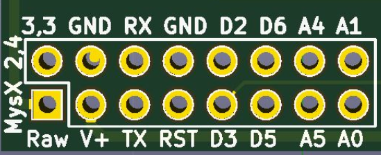
              @anticimex Well - its 2.4 header (mostly for stability) but its only actively 2.1 which is used so Im not sure.

              Controller: Proxmox VM - Home Assistant
              MySensors GW: Arduino Uno - W5100 Ethernet, Gw Shield Nrf24l01+ 2,4Ghz
              MySensors GW: Arduino Uno - Gw Shield RFM69, 433mhz
              RFLink GW - Arduino Mega + RFLink Shield, 433mhz

              1 Reply Last reply
              0
              • simboS Offline
                simboS Offline
                simbo
                wrote on last edited by
                #7

                In your next rev, perhaps you increase the spacing between the voltage regulator and the MOFSET to accommodate heat sinks? The minimum would be 2.54mm.

                sundberg84S 1 Reply Last reply
                0
                • simboS simbo

                  In your next rev, perhaps you increase the spacing between the voltage regulator and the MOFSET to accommodate heat sinks? The minimum would be 2.54mm.

                  sundberg84S Offline
                  sundberg84S Offline
                  sundberg84
                  Hardware Contributor
                  wrote on last edited by
                  #8

                  @simbo sure! I was thinking only the mosfet would need a heatsink so my plan was to attach it on the back. The maximum led strip I have is 2.5m and I didn't have to use any heatsink so didn't think much about it. Do you have some sort of heatsink link you prefer (with measurements) I can have a look at.

                  Controller: Proxmox VM - Home Assistant
                  MySensors GW: Arduino Uno - W5100 Ethernet, Gw Shield Nrf24l01+ 2,4Ghz
                  MySensors GW: Arduino Uno - Gw Shield RFM69, 433mhz
                  RFLink GW - Arduino Mega + RFLink Shield, 433mhz

                  1 Reply Last reply
                  1
                  • Y Offline
                    Y Offline
                    yoshida
                    wrote on last edited by
                    #9

                    Hi, some -maybe- silly questions:

                    In the diagram you marked MysX connector number 9 as the "LED1", but that's the A5, and not the D3 where I see it is connected. (just asking this to be sure that I understand right the board, and the diagram)
                    So this is only a typo, right?

                    Other question is that I can use the mysensors LED dimmer example sketch with the rotary encoder with this board, right? It needs 4 digital pins, and MysX has 4: "D2, D3, D5, D6".

                    So I just have to replace in the sketch the #define KNOB_ENC_PIN_1 4 to #define KNOB_ENC_PIN_1 2?

                    "#define LED_PIN 3 // Arduino pin attached to MOSFET Gate pin
                    #define KNOB_ENC_PIN_1 4 // Rotary encoder input pin 1
                    #define KNOB_ENC_PIN_2 5 // Rotary encoder input pin 2
                    #define KNOB_BUTTON_PIN 6 // Rotary encoder button pin"

                    sundberg84S 1 Reply Last reply
                    0
                    • Y yoshida

                      Hi, some -maybe- silly questions:

                      In the diagram you marked MysX connector number 9 as the "LED1", but that's the A5, and not the D3 where I see it is connected. (just asking this to be sure that I understand right the board, and the diagram)
                      So this is only a typo, right?

                      Other question is that I can use the mysensors LED dimmer example sketch with the rotary encoder with this board, right? It needs 4 digital pins, and MysX has 4: "D2, D3, D5, D6".

                      So I just have to replace in the sketch the #define KNOB_ENC_PIN_1 4 to #define KNOB_ENC_PIN_1 2?

                      "#define LED_PIN 3 // Arduino pin attached to MOSFET Gate pin
                      #define KNOB_ENC_PIN_1 4 // Rotary encoder input pin 1
                      #define KNOB_ENC_PIN_2 5 // Rotary encoder input pin 2
                      #define KNOB_BUTTON_PIN 6 // Rotary encoder button pin"

                      sundberg84S Offline
                      sundberg84S Offline
                      sundberg84
                      Hardware Contributor
                      wrote on last edited by sundberg84
                      #10

                      @yoshida hi!

                      Im not sure where you get that #9 should be A5? Looks right to me. The pin is connected to pin 9, and that is D3.

                      0_1535522995805_62649016-d746-4ccb-b360-4e8b7ee1405b-image.png 0_1535523011377_7f2024c3-afd9-49ee-bb02-95e6e45275a9-image.png

                      For a rotary encoder, it depends on your input - but don't you want an analog signal in? In that case you use the analog pins.

                      Edit: offcourse, if you use a module converting it to digital like described in the the build section you use a digital pin.

                      Controller: Proxmox VM - Home Assistant
                      MySensors GW: Arduino Uno - W5100 Ethernet, Gw Shield Nrf24l01+ 2,4Ghz
                      MySensors GW: Arduino Uno - Gw Shield RFM69, 433mhz
                      RFLink GW - Arduino Mega + RFLink Shield, 433mhz

                      1 Reply Last reply
                      0
                      Reply
                      • Reply as topic
                      Log in to reply
                      • Oldest to Newest
                      • Newest to Oldest
                      • Most Votes


                      27

                      Online

                      11.7k

                      Users

                      11.2k

                      Topics

                      113.1k

                      Posts


                      Copyright 2025 TBD   |   Forum Guidelines   |   Privacy Policy   |   Terms of Service
                      • Login

                      • Don't have an account? Register

                      • Login or register to search.
                      • First post
                        Last post
                      0
                      • MySensors
                      • OpenHardware.io
                      • Categories
                      • Recent
                      • Tags
                      • Popular