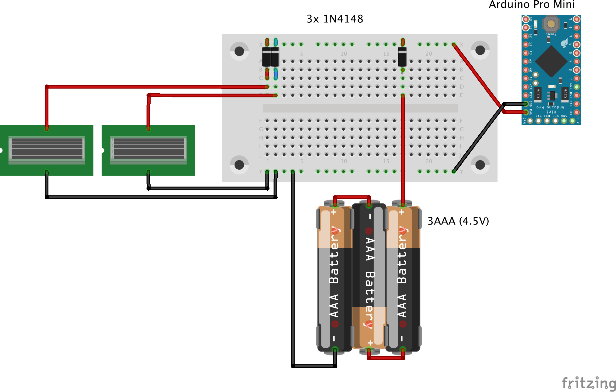
Solar cell support with non-rechargeable batteries
-
@neverdie the problem is both charger and booster: if you have a dumb booster when voltage drops below its operating voltage, it starts draining more current than the solar cell is able to provide, so you need extra components to cut the power to booster until supercapacitor reaches at least 1v but at this point you can very well use a circuit specific for supercaps energy harvesting. I have been lucky at the moment that my solar node is now performing well on the north side of the house with no direct sunlight, but if I am going to get several days of bad weather I would still need to jump start the node by manually charging the supercaps
@gohan
I say avoid all that and just use a dead simple circuit like:
https://www.openhardware.io/view/382/Tiny-Solar-Charger-for-27v-Mote-Supercap
and power your node directly from the supercap.It's simple. It's cheap. It's tested. It works. Why complicate matters?
-
@gohan
I say avoid all that and just use a dead simple circuit like:
https://www.openhardware.io/view/382/Tiny-Solar-Charger-for-27v-Mote-Supercap
and power your node directly from the supercap.It's simple. It's cheap. It's tested. It works. Why complicate matters?
-
@gunther I don't. Ditch the LDO on the pro min. The pro mini can run just fine even down to 1.8v. Pick sensors that also do that, and then you're golden. BME280 and si7021 can both do that. Most wireless can also run fine even as low as 1.8v.
-
@gunther I don't. Ditch the LDO on the pro min. The pro mini can run just fine even down to 1.8v. Pick sensors that also do that, and then you're golden. BME280 and si7021 can both do that. Most wireless can also run fine even as low as 1.8v.
-
@neverdie Will try! But that means the NRF24L01 is also out? And am I correct to connect the 2.7V to VCC not RAW?
@gunther said in Solar cell support with non-rechargeable batteries:
And am I correct to connect the 2.7V to VCC not RAW?
Yes. Also NRF24L01 voltage range is 3.6-1.8v, so it's not a problem either.
-
@gohan That's true, but if it's a problem, use a larger supercap. The pricing is non-linear, so, for instance, twice the farads costs less than twice as much. 10x the farads costs much less than 10x as much. I don't think the economics generally favors boosting. You simply have capacity that never gets used.
-
@gunther said in Solar cell support with non-rechargeable batteries:
And am I correct to connect the 2.7V to VCC not RAW?
Yes. Also NRF24L01 voltage range is 3.6-1.8v, so it's not a problem either.
Thank you all for the information!
@neverdie Ok, so now I have desoldered the Arduino Pro Mini power regulator and I now see a sleep current of 6µA with 3.2V.
One thing I see is that the node only works down to 3V. With 2.5V it is not stable anymore. This is just the Arduino Pro Mini with attached NRF24L01. Maybe this is expected? I checked visually that I have indeed the 8MHz variant.
I just tried to test it with parts I could get my hands on.Could someone please tell me why the Battery Powering page advises to cut Vout? And what is it? It seems to me that this disconnects the Vcc on the shorter end? To what consumption does the connection lead. I find it convenient to have another Vcc pin available.
-
Thank you all for the information!
@neverdie Ok, so now I have desoldered the Arduino Pro Mini power regulator and I now see a sleep current of 6µA with 3.2V.
One thing I see is that the node only works down to 3V. With 2.5V it is not stable anymore. This is just the Arduino Pro Mini with attached NRF24L01. Maybe this is expected? I checked visually that I have indeed the 8MHz variant.
I just tried to test it with parts I could get my hands on.Could someone please tell me why the Battery Powering page advises to cut Vout? And what is it? It seems to me that this disconnects the Vcc on the shorter end? To what consumption does the connection lead. I find it convenient to have another Vcc pin available.
@gunther said in Solar cell support with non-rechargeable batteries:
One thing I see is that the node only works down to 3V. With 2.5V it is not stable anymore. This is just the Arduino Pro Mini with attached NRF24L01. Maybe this is expected? I checked visually that I have indeed the 8MHz variant.
Did you remember to remove the LDO? Because otherwise it gets backfed, which is not what you want.
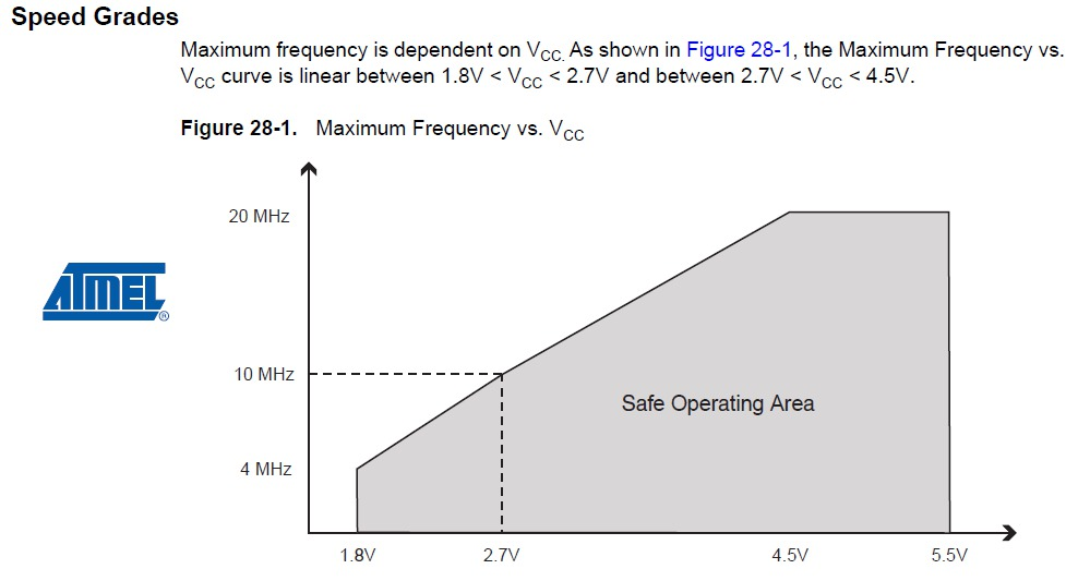
Also, yes, in theory you are running it out of Atmel's official spec if running at 8mhz at 1.8v, but I don't know and haven't read of even a single person who has ever had a problem with doing so. Doing this is very common.
-
BTW, I pretty thoroughly explored the idea of running a mote from solar and a supercap on this other thread, where I tried a whole gamut of different approaches: https://forum.mysensors.org/topic/5274/powering-mote-24-7-using-only-a-supercap-and-solar
In summary, though, I do think that for most people, the approach of using a diode and LDO in concert with the solar cell and supercap is going to be the simplest and best solution for them.Good luck!
-
Thank you all for the information!
@neverdie Ok, so now I have desoldered the Arduino Pro Mini power regulator and I now see a sleep current of 6µA with 3.2V.
One thing I see is that the node only works down to 3V. With 2.5V it is not stable anymore. This is just the Arduino Pro Mini with attached NRF24L01. Maybe this is expected? I checked visually that I have indeed the 8MHz variant.
I just tried to test it with parts I could get my hands on.Could someone please tell me why the Battery Powering page advises to cut Vout? And what is it? It seems to me that this disconnects the Vcc on the shorter end? To what consumption does the connection lead. I find it convenient to have another Vcc pin available.
-
@neverdie said in Solar cell support with non-rechargeable batteries:
Did you remember to remove the LDO? Because otherwise it gets backfed, which is not what you want.
I don't understand, the LDO is needed for charging the supercaps?
@neverdie said in Solar cell support with non-rechargeable batteries:
Also, yes, in theory you are running it out of Atmel's official spec if running at 8mhz at 1.8v, but I don't know and haven't read of even a single person who has ever had a problem with doing so. Doing this is very common.
I would be very glad if I got to lower voltages, I am just trying to understand why I can't get below ~2.9V (at the Arduino).
@Nca78 said in Solar cell support with non-rechargeable batteries:
@gunther did you update fuses to lower BOD ?
Still getting to grips with the terms. You mean the 1N4148 diodes? And BOD refers to lower voltage difference?No, not yet. I just plugged together parts, I could get my hands on to try to understand everything. I will then order the parts that are ideal.
@NeverDie I promise to read all comments in existing threads!
One thing that got me sidetracked is that I do not understand the analog read:
I successfully confirmed that the Arduino Nano when attached to USB uses 2^10 channels with 1.1V reference.For the Arduino Mini Pro I also see 2^10 = 1024 channels with 1.1V reference when the power support comes from USB, what I assume to be a high quality power supply.
However, when I run it off the capacitors + solar cells giving 3.3V I only get 2^8 = 256 channels with what appears to be ~1.1V reference. That is when I apply a voltage >1.1V I always get 255.
I added various capacitors from 0.1-4.7 µF in parallel but that didn't change anything.
How can that be? -
@neverdie said in Solar cell support with non-rechargeable batteries:
Did you remember to remove the LDO? Because otherwise it gets backfed, which is not what you want.
I don't understand, the LDO is needed for charging the supercaps?
@neverdie said in Solar cell support with non-rechargeable batteries:
Also, yes, in theory you are running it out of Atmel's official spec if running at 8mhz at 1.8v, but I don't know and haven't read of even a single person who has ever had a problem with doing so. Doing this is very common.
I would be very glad if I got to lower voltages, I am just trying to understand why I can't get below ~2.9V (at the Arduino).
@Nca78 said in Solar cell support with non-rechargeable batteries:
@gunther did you update fuses to lower BOD ?
Still getting to grips with the terms. You mean the 1N4148 diodes? And BOD refers to lower voltage difference?No, not yet. I just plugged together parts, I could get my hands on to try to understand everything. I will then order the parts that are ideal.
@NeverDie I promise to read all comments in existing threads!
One thing that got me sidetracked is that I do not understand the analog read:
I successfully confirmed that the Arduino Nano when attached to USB uses 2^10 channels with 1.1V reference.For the Arduino Mini Pro I also see 2^10 = 1024 channels with 1.1V reference when the power support comes from USB, what I assume to be a high quality power supply.
However, when I run it off the capacitors + solar cells giving 3.3V I only get 2^8 = 256 channels with what appears to be ~1.1V reference. That is when I apply a voltage >1.1V I always get 255.
I added various capacitors from 0.1-4.7 µF in parallel but that didn't change anything.
How can that be? -
@gohan But how do I handle the different voltages? The Nano has 5V powered from USB, and I supplied the Mini Pro with 3.3V. But can't connecting the SPI pins lead to havoc? I read stuff in the ArduinoISP sketch like :
MISO °. . 5V (!) Avoid this pin on Due, Zero...Should I just leave out the MISO connection?
-
@gohan But how do I handle the different voltages? The Nano has 5V powered from USB, and I supplied the Mini Pro with 3.3V. But can't connecting the SPI pins lead to havoc? I read stuff in the ArduinoISP sketch like :
MISO °. . 5V (!) Avoid this pin on Due, Zero...Should I just leave out the MISO connection?
@gunther said in Solar cell support with non-rechargeable batteries:
@gohan But how do I handle the different voltages? The Nano has 5V powered from USB, and I supplied the Mini Pro with 3.3V. But can't connecting the SPI pins lead to havoc? I read stuff in the ArduinoISP sketch like :
MISO °. . 5V (!) Avoid this pin on Due, Zero...Should I just leave out the MISO connection?
As long as you don't have radio connected (it will not survive 5V Vcc) or 3.3V sensors, you can connect Vcc of your pro mini with 5V, atmega328 can run at this voltage without problem.
5V pro mini = 5V regulator + 16MHz crystal + 16MHz bootloader
3.3V pro mini = 3.3V regulator + 8MHz crystal + 8MHz bootloader
IC is exactly the same.So if you bypass the regulator by providing 5V directly to Vcc your board and I/Os will run at 5V.
[Edit] if you have radio and/or 3.3V sensors connected, you need to connect vcc of the pro mini with 3.3V and use a voltage converter for the SPI pins.
-
@Nca78 Yes, that should have been clear to me by now.
I just lost some time trying to burn the boot loader as always I got this error:
avrdude: stk500_getparm(): (a) protocol errorChecked, tested and even redid the soldering to exclude any wiring problems. Turns out adding a cap (0.1 µF in my case) between the programmers GND and RST did the trick.
Thank you all!
-
As this thread turns into my personal highlights of silly mistakes: Another word of caution for anybody who wants raw battery values sent:
sendBatteryLevel only uses 8-bit: i.e. value from 0-255. Don't try to send your raw 10-bit sensed input from e.g. A0 directly with it.bool sendBatteryLevel(const uint8_t level, const bool ack = false);Make sure you divide by 4 or use something like:
int sensorValue = analogRead(ANALOGUE_SENSE_PIN) >> 2;
    sendBatteryLevel(sensorValue);
Hello! It looks like you're interested in this conversation, but you don't have an account yet.
Getting fed up of having to scroll through the same posts each visit? When you register for an account, you'll always come back to exactly where you were before, and choose to be notified of new replies (either via email, or push notification). You'll also be able to save bookmarks and upvote posts to show your appreciation to other community members.
With your input, this post could be even better 💗
Register Login