Please help! Arduino UNO + RFM69HW (TSM:INIT:TSP FAIL)
-
Hello!
Please help me understand the problem.My relay node is built on Arduino UNO + RFM69HW 868 mhz
My gateway node is built on NodeMcu + RFM69HW 868 mhz
Controller Openhab 2.2 (Openhabian + Raspberry Pi 3)
MySensors library 2.2Here's what the port monitor shows:
16 MCO:BGN:INIT REPEATER,CP=RRNRA---,VER=2.2.0
26 MCO:BGN:BFR
27 TSM:INIT
28 TSF:WUR:MS=0
80 !TSM:INIT:TSP FAIL
81 TSM:FAIL:CNT=1
83 TSM:FAIL:DIS
84 TSF:TDI:TSL
The code of my relay node:
/**
 * The MySensors Arduino library handles the wireless radio link and protocol
 * between your home built sensors/actuators and HA controller of choice.
 * The sensors forms a self healing radio network with optional repeaters. Each
 * repeater and gateway builds a routing tables in EEPROM which keeps track of the
 * network topology allowing messages to be routed to nodes.
 *
 * Created by Henrik Ekblad <henrik.ekblad@mysensors.org>
 * Copyright (C) 2013-2015 Sensnology AB
 * Full contributor list: https://github.com/mysensors/Arduino/graphs/contributors
 *
 * Documentation: http://www.mysensors.org
 * Support Forum: http://forum.mysensors.org
 *
 * This program is free software; you can redistribute it and/or
 * modify it under the terms of the GNU General Public License
 * version 2 as published by the Free Software Foundation.
 *
 *******************************
 *
 * REVISION HISTORY
 * Version 1.0 - Henrik Ekblad
 *
 * DESCRIPTION
 * Example sketch showing how to control physical relays.
 * This example will remember relay state after power failure.
 * http://www.mysensors.org/build/relay
 */

// Enable debug prints to serial monitor
#define MY_DEBUG

// Enable and select radio type attached
//#define MY_RADIO_NRF24
//#define MY_RADIO_NRF5_ESB
#define MY_RADIO_RFM69
//#define MY_RADIO_RFM95

// Enable repeater functionality for this node
#define MY_REPEATER_FEATURE

#include <MySensors.h>

#define RELAY_PIN 4  // Arduino Digital I/O pin number for first relay (second on pin+1 etc)
#define NUMBER_OF_RELAYS 1 // Total number of attached relays
#define RELAY_ON 1  // GPIO value to write to turn on attached relay
#define RELAY_OFF 0 // GPIO value to write to turn off attached relay


void before()
{
	for (int sensor=1, pin=RELAY_PIN; sensor<=NUMBER_OF_RELAYS; sensor++, pin++) {
		// Then set relay pins in output mode
		pinMode(pin, OUTPUT);
		// Set relay to last known state (using eeprom storage)
		digitalWrite(pin, loadState(sensor)?RELAY_ON:RELAY_OFF);
	}
}

void setup()
{

}

void presentation()
{
	// Send the sketch version information to the gateway and Controller
	sendSketchInfo("Relay", "1.0");

	for (int sensor=1, pin=RELAY_PIN; sensor<=NUMBER_OF_RELAYS; sensor++, pin++) {
		// Register all sensors to gw (they will be created as child devices)
		present(sensor, S_BINARY);
	}
}


void loop()
{

}

void receive(const MyMessage &message)
{
	// We only expect one type of message from controller. But we better check anyway.
	if (message.type==V_STATUS) {
		// Change relay state
		digitalWrite(message.sensor-1+RELAY_PIN, message.getBool()?RELAY_ON:RELAY_OFF);
		// Store state in eeprom
		saveState(message.sensor, message.getBool());
		// Write some debug info
		Serial.print("Incoming change for sensor:");
		Serial.print(message.sensor);
		Serial.print(", New status: ");
		Serial.println(message.getBool());
	}
}
Photo of my relay node:

Please tell me what I'm doing wrong and how to fix this problem? -
Hello,
A few things are wrong I think:
- RFM69 'HW' variant needs this define in your relay sketch:
#define MY_IS_RFM69HWyou can check docs here ;) https://www.mysensors.org/download/sensor_api_20#configuration
- RFM69 is not 5v tolerant on VCC, nor the spi bus. you're using a UNO, I understand you're using 3v, but UNO mcu is powered by 5v and outputs 5v signals on spi bus as (I think the 'not 5v tolerant' is in docs too. maybe we should highlight it
-
@scalz, many thanks for the reply and the desire to help!
I understand what you are talking about, but for now I can figure out how to solve it.
Perhaps you have ideas?Replace Arduino board with Pro Mini 3.3V?
-
@mfalkvidd I'm not properly connected? In the photo above. He's turned over there.

-
That is the voltage regulator like the one on the arduino that supplies the 3.3v pin, but the Arduino is using 5v also on the other GPIO pins and that usually could kill the RFM69 that should operate at 3.5V max on data pins
-
@vladimir the shopping guide at https://www.mysensors.org/build/connect_radio lists a logic level shifter.
@mfalkvidd thank you very much for your help! :+1: :v:
-
I hope you didn't fry the rfm69, so in case you are still having problems with the level shifter connected try with another module
-
-
@mfalkvidd Thank you! I hope I can figure it out. To regret, my knowledge of English is not very great. As I understand it, the connection scheme will be the most similar to this:
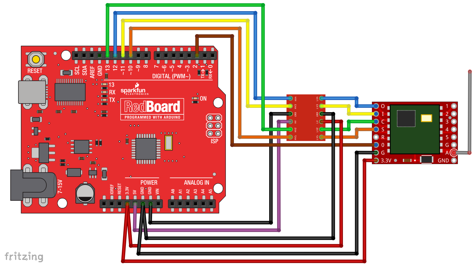
I'm right? -
@vladimir yes, that looks great (except for the brown cable that doesn't go through the level shifter)
@mfalkvidd So I do not like the converter for 4 channels?
Here this is indicated by the link you gave me above

It will take 5? More precisely 8-channel version? -
@mfalkvidd So I do not like the converter for 4 channels?
Here this is indicated by the link you gave me above
It will take 5? More precisely 8-channel version? -
@vladimir you will need to shift all signals. You can use multiple 4x boards, or a bigger board.
Edit: maybe miso and dio0 don't need to be shifted, since the Arduino only reads from it. But I am not 100% sure.
@mfalkvidd Thank you! :raised_hands: I'll try tomorrow.
Hello! It looks like you're interested in this conversation, but you don't have an account yet.
Getting fed up of having to scroll through the same posts each visit? When you register for an account, you'll always come back to exactly where you were before, and choose to be notified of new replies (either via email, or push notification). You'll also be able to save bookmarks and upvote posts to show your appreciation to other community members.
With your input, this post could be even better 💗
Register Login