Water pressure sensors?
-
@gohan that's where you are wrong.
"In many countries there are obligations to measure and report SSO occurrence using real-time telemetry to warn the public, bathers and shellfishery operators."From https://en.wikipedia.org/wiki/Sanitary_sewer_overflow
Now that we've completely derailed this thread, could we get back on topic?
-
If you could derive a small pipe from the main sewage line, you could could then have a transducer at the end to measure pressure without requiring it to go submerged.
-
If you could derive a small pipe from the main sewage line, you could could then have a transducer at the end to measure pressure without requiring it to go submerged.
-
@gohan thanks. Yes, that's a solution that could work. (technically, the "inside" part of the sensor would still be submerged which probably is necessary)
@mfalkvidd Not so.... You can install a sensor on a sealed stack (vertical pipe) as @gohan suggested, sealed to the crown of the sewer or drain (a Tee or saddle fitting), the air pressure from the relative hydraulic head will create air pressure which can be correlated to hydraulic head. Whereas the sensor may get moisture in the air it will never be actually submerged, which you generally do not want in sewage anyway due to grease etc and various objects which customers do deposit...
Another option is ultrasonics in a vertical pipe venting to atmosphere thereby contact free.. Whether you could get a decent interpretation in a tube from a DYP-ME007Y or similar I do not know, but commercial systems use just such an arrangement.... -
Thanks for the input @zboblamont
I can't mount a 10m vertical pipe on top of the sewage pipe, so I don't think ultrasound is a viable alternative unfortunately.@mfalkvidd 10m? Wow, that is one very large hydraulic head you're measuring if it's a storm overflow or similar... Oslo's trunk sewer system? A sealed pressure transducer would be your best bet at that head, holding it in a fixed position and running the cable will be a challenge...
Oops, just read your follow up... -
But it is missing the entire enclosure, it is the bare sensor. The one I posted was ready to be bolted into place
-
@mfalkvidd Perhaps if you expand on the objective and location it might help narrow down options.
eg - Is this a pressurised pipe below the surface which may be tapped into or a deep well vented to atmosphere? Does the site have power or is this a remote location?If the intent is a submerged logger type device occasionally retrieved and downloaded at the surface, an adaption of the cavepearlproject.org format might suit.
If this is to report to the surface in real time from a vented chamber surcharging to 10m, cabling brings a host of problems, not least low voltage operation... Typical commercial devices for such applications are sealed pressure probes operating at over 9v with a 4-20mA output, and pricetags north of 400 euro...
A rigid pipe with a transducer sealed and mounted on the top will work when the pipe is purged (compressor/foot pump), the static air pressure thereafter relates directly to depth of hydraulic submergence.. -
@mfalkvidd Perhaps if you expand on the objective and location it might help narrow down options.
eg - Is this a pressurised pipe below the surface which may be tapped into or a deep well vented to atmosphere? Does the site have power or is this a remote location?If the intent is a submerged logger type device occasionally retrieved and downloaded at the surface, an adaption of the cavepearlproject.org format might suit.
If this is to report to the surface in real time from a vented chamber surcharging to 10m, cabling brings a host of problems, not least low voltage operation... Typical commercial devices for such applications are sealed pressure probes operating at over 9v with a 4-20mA output, and pricetags north of 400 euro...
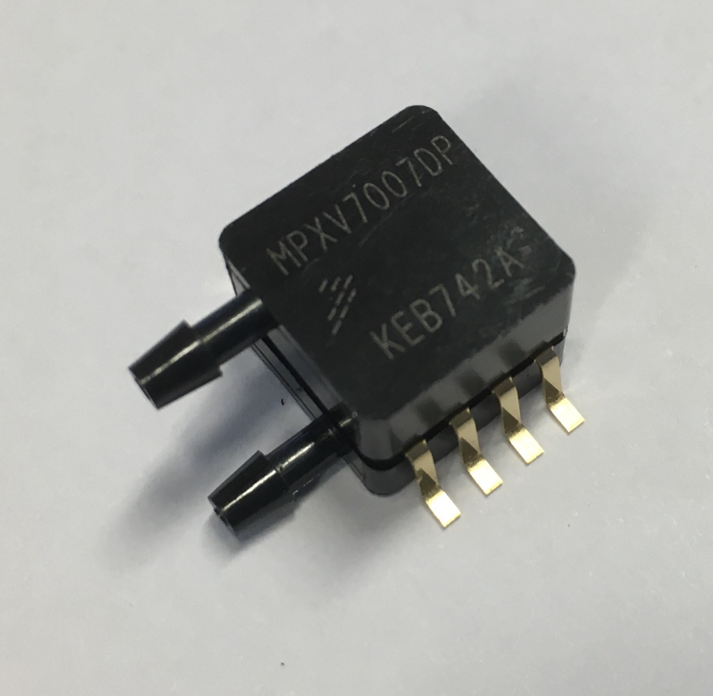
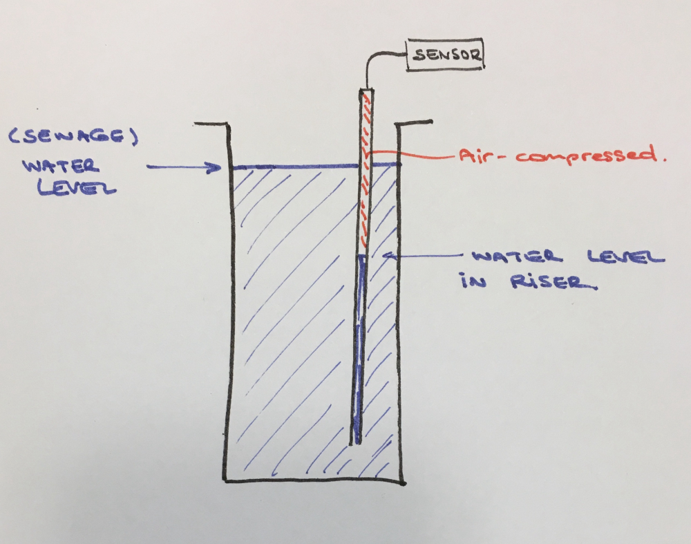
A rigid pipe with a transducer sealed and mounted on the top will work when the pipe is purged (compressor/foot pump), the static air pressure thereafter relates directly to depth of hydraulic submergence..Have a look at freescale sensors. i.e. MXP-type sensors. You could ask for samples (they will provide up to 5 pcs. for free). Cost around $15 pcs. normally.
You'd mount such a sensor on top of a riser (air-tight) and when the (sewage) water rises, the air-pocket is compressed proportionally. This is how I measure the ground-water level at my location and it helps me to keep my basement free of water. Works flawlessly!
BR,
Boozz
-
@mfalkvidd I still cannot understand why cannot you mount a water sensor in the riser tube or just above bottom?
-
@mfalkvidd how about this if you insist on a water pressure sensor
https://www.bluerobotics.com/store/electronics/bar30-sensor-r1/ -
I'm guessing this is not a hobby request (based on the photo of the manhole cover). I've looked at pressure sensors for level detection many times for automotive applications and can offer the following:
-
o-rings don't seal. For your application you need either a hermetic seal or fully potted assembly
-
open tubes will fill / drain based on condensation temperature changes etc.
-
Freezing is often an issue but I'll guess at you depth you don't have to worry about it.
Have you considered a pressure switch? It wouldn't necessarily solve the seal problem but might work for you. Still thinking.... the pressure switch might be hard to self test. At least on the pressure you can see small changes, suggesting the transducer is functioning.
you might find this link useful: submersible transducer
If you are looking for a lower cost solution, look for "absolute" pressure sensors as opposed to "gauge" pressure sensors.
If you want to go the potted route, you might look at this: [link text](absolute xducer). If the cabling was completely potted in a suitable material, this could work for you.
-
-
Maybe just measure the height of the effluent? It should be proportional to the pressure. It seems like what you care about most is overflows anyway.
-
I use a pressure sensor on the output of the pump that feeds my solar hot water panel. I think I got mine on Amazon. They use a lot of them in automotive applications. They come in lots of different pressure ranges. On mine I think I first had to figure out how to convert the analog input port reading from a number to a raw voltage. Most important you will first need to take a reading of your sensor in open air. FYI most of these sensors will run with any gas or liquid i.e. air, oil, water, etc.
The math for the sensors looks something like this:
PSI=(Sensor Voltage - open air voltage)/7This is why we need the open air reading. If your current voltage reading and your open air voltage are the same that means you current pressure would be 0 zero, right?
The next part the 7 is a little more complicated but remember it's just a number and I think I got mine right off the spec sheet for the sensor. If you plotted a graph for every reading from 0 psi to the sensors max pressure the slope of that line is where the number 7 comes from. Technically it's the slope of the linear regression. But we don't care how we got it because someone even nerdier than than me did the math and it's on the spec sheet. That's why we buy a new one instead of taking one off an old motor at the junkyard.
With that info I first had to determine the raw sensor voltage. The Arduino returns a value of 0 - 1023 for a voltage of 0 - 5 volts (I mostly use 5V Arduino's) so to find the voltage I use the following line in my code.
First get the raw sensor value.
float rawSensorValue = analogRead(tankPumpPressurePin); // Read Pin A15 Value range 0-1023Then convert that value into a voltage.
float voltage = rawSensorValue * (5.0 / 1023.0);Then to get the actual pressure I had to do a little more math with the following line. On my sensor the open air reading was 109.
tankPumpPressure = ((rawSensorValue - 109) / 7);
The whole thing looks like this.
void readTankPumpPressure()
{
// Read Pin A15 Value range 0-1023
float rawSensorValue = analogRead(tankPumpPressurePin);
float voltage = rawSensorValue * (5.0 / 1023.0);
tankPumpPressure = ((rawSensorValue - 109) / 7); // Should be in PSI.
currentTankPumpPressure = tankPumpPressure; send(msg_tank_pump_pressure.setDestination(GW_ID).setSensor(Tank_Pump_Pressure_ID).set(currentTankPumpPressure, 1));
}I hope this helped I also take flow reading.
@rwoerz
Sorry to say you can't use a tube submerged in the water. That will only work for a very short time. I was going to use that method to take a pressure reading to see how much head (water depth) was in my water well. The problem as I was told is the air in the tube is eventually absorbed by the water ending with a pressure of zero. If you had a way of blowing the tube clear of water just before you took each reading that would work.