AC-DC at own


-
Thanks. What is the purpose of the inductor at the output of the circuit? why not to use one also after the bridge rectifier?
@jeremushka said in AC-DC at own:
Thanks. What is the purpose of the inductor at the output of the circuit? why not to use one also after the bridge rectifier?
inductor at output is to reduce riple
on hight voltage side will be better to put filter but there is no place for it
inductor as such will not bring too much valuesense and drive
-
@jeremushka said in AC-DC at own:
Thanks. What is the purpose of the inductor at the output of the circuit? why not to use one also after the bridge rectifier?
inductor at output is to reduce riple
on hight voltage side will be better to put filter but there is no place for it
inductor as such will not bring too much value@axillent thank you. it is clear information :) very nice work
-
@jeremushka for sure
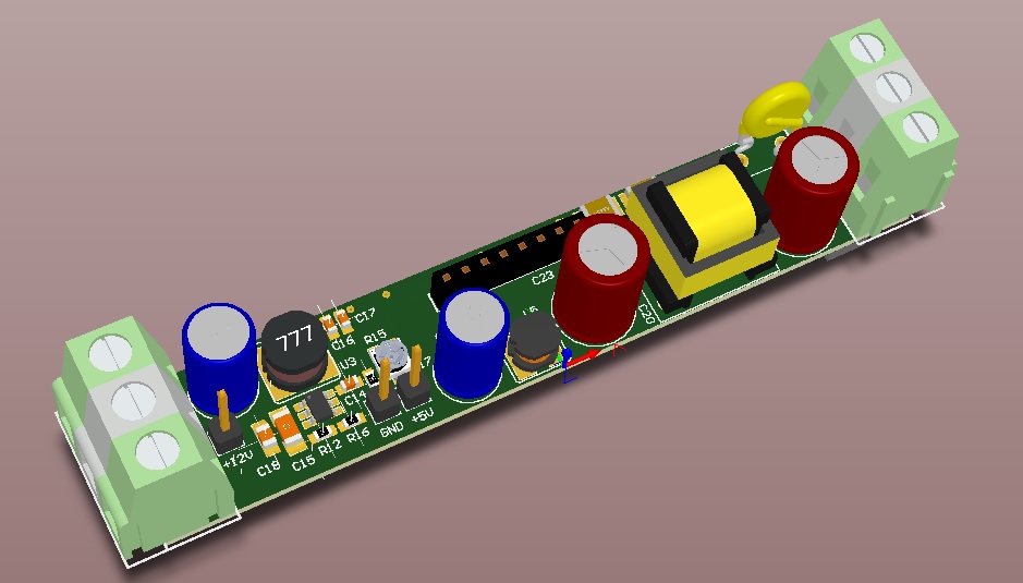
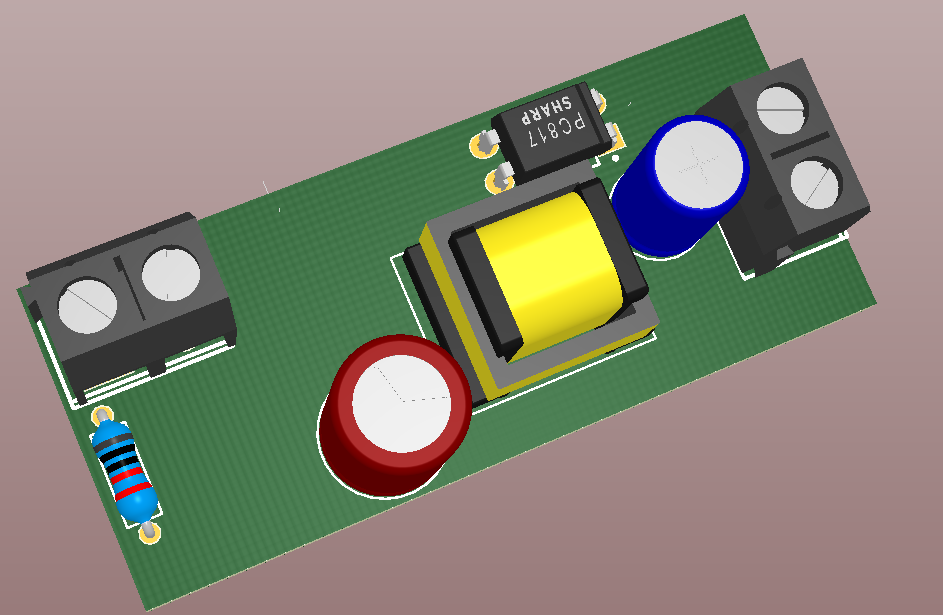
schematic is standard, simplified version from datasheet
D8, D11 and R22 are optional, it is to be able to source power from different sources (for example different phases, or from main power and from generator).
D12 I'm using 11V to have output at about 12.1V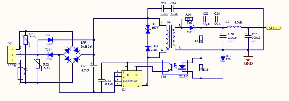
@axillent said in AC-DC at own:
@jeremushka for sure
schematic is standard, simplified version from datasheet
D8, D11 and R22 are optional, it is to be able to source power from different sources (for example different phases, or from main power and from generator).
D12 I'm using 11V to have output at about 12.1Vsome questions regarding the schematics:
- does TVS diode 600W 5V is efficient enough? or absolutely need cut off at 160V such as 600W 160A ?
- for the Fuse, a slow fuse 10A is enough i think, isn't it?
-
@axillent said in AC-DC at own:
@jeremushka for sure
schematic is standard, simplified version from datasheet
D8, D11 and R22 are optional, it is to be able to source power from different sources (for example different phases, or from main power and from generator).
D12 I'm using 11V to have output at about 12.1Vsome questions regarding the schematics:
- does TVS diode 600W 5V is efficient enough? or absolutely need cut off at 160V such as 600W 160A ?
- for the Fuse, a slow fuse 10A is enough i think, isn't it?
@jeremushka said in AC-DC at own:
some questions regarding the schematics:
- does TVS diode 600W 5V is efficient enough? or absolutely need cut off at 160V such as 600W 160A ?
- for the Fuse, a slow fuse 10A is enough i think, isn't it?
TVS need to be for 120-160V in case you supply 230V AC. You can refer to linkswitch designer for your specific needs.
The purpose of this TVS is to be a snubber because of inductive load. Instead of TVS an RC snubber could be used.it is 3Watts supply, 0.5-1A slow fuse is fine
sense and drive
-
@jeremushka said in AC-DC at own:
some questions regarding the schematics:
- does TVS diode 600W 5V is efficient enough? or absolutely need cut off at 160V such as 600W 160A ?
- for the Fuse, a slow fuse 10A is enough i think, isn't it?
TVS need to be for 120-160V in case you supply 230V AC. You can refer to linkswitch designer for your specific needs.
The purpose of this TVS is to be a snubber because of inductive load. Instead of TVS an RC snubber could be used.it is 3Watts supply, 0.5-1A slow fuse is fine
@axillent said in AC-DC at own:
@jeremushka said in AC-DC at own:
some questions regarding the schematics:
- does TVS diode 600W 5V is efficient enough? or absolutely need cut off at 160V such as 600W 160A ?
- for the Fuse, a slow fuse 10A is enough i think, isn't it?
TVS need to be for 120-160V in case you supply 230V AC. You can refer to linkswitch designer for your specific needs.
The purpose of this TVS is to be a snubber because of inductive load. Instead of TVS an RC snubber could be used.it is 3Watts supply, 0.5-1A slow fuse is fine
Thanks for the answer. i will play with this LNK component. never used it before. I am curious to know the performances of it.
for your design, you have added others functions on your PCB ? such as DC-DC converter ... etc.. ? -
@axillent said in AC-DC at own:
@jeremushka said in AC-DC at own:
some questions regarding the schematics:
- does TVS diode 600W 5V is efficient enough? or absolutely need cut off at 160V such as 600W 160A ?
- for the Fuse, a slow fuse 10A is enough i think, isn't it?
TVS need to be for 120-160V in case you supply 230V AC. You can refer to linkswitch designer for your specific needs.
The purpose of this TVS is to be a snubber because of inductive load. Instead of TVS an RC snubber could be used.it is 3Watts supply, 0.5-1A slow fuse is fine
Thanks for the answer. i will play with this LNK component. never used it before. I am curious to know the performances of it.
for your design, you have added others functions on your PCB ? such as DC-DC converter ... etc.. ?@jeremushka said in AC-DC at own:
Thanks for the answer. i will play with this LNK component. never used it before. I am curious to know the performances of it.
for your design, you have added others functions on your PCB ? such as DC-DC converter ... etc.. ?my DIN desing is universal. it is for the set of different devices with common 12V power
dc-dc is used to feed MCU from 12V -
@axillent, i am designing your board on altium designer. However, i am facing difficulties with the footprint of the transformer. Is it possible to share it or your pcb file?
-
@axillent, i am designing your board on altium designer. However, i am facing difficulties with the footprint of the transformer. Is it possible to share it or your pcb file?
-
@jeremushka I do have this footprint in altium but the library is big. do you know how to export a single element?
@axillent yes you are right. Same for me.
Usually, what i am doing is to create a project library from Schematic. For that, i open the Schematic. Then Design menu => make a schematic library. All the components and footprint of the Schematic will be copied and integrated. If schematic is huge or some components no need to extract, then i remove the one i don't need from the schematic library. At this end, you may have for example only the transformer component and footprint in the schematic library and you can extract this library for dxternal purpose. It is maybe not the best methodology (i don't know) but it works. -
@jeremushka said in AC-DC at own:
some questions regarding the schematics:
- does TVS diode 600W 5V is efficient enough? or absolutely need cut off at 160V such as 600W 160A ?
- for the Fuse, a slow fuse 10A is enough i think, isn't it?
TVS need to be for 120-160V in case you supply 230V AC. You can refer to linkswitch designer for your specific needs.
The purpose of this TVS is to be a snubber because of inductive load. Instead of TVS an RC snubber could be used.it is 3Watts supply, 0.5-1A slow fuse is fine
-
Regarding the OP, there's an easier way: if every time you throw out some broken, old, or obsolete gizmo or tool you hold on to just its AC-DC power-supply/charger, pretty soon you'll be up to your eyeballs in power-supplies/chargers and have a lot to choose from when you do a project. With a big enough collection, you'll likely find a match for your project straight away. If not, then in all likelihood all you'll need is just a DC-DC converter, which are cheap (as little as $1 or less for some of them), and there's nothing scary about them.
Problem is safely solved for very little time and money. Even better, the AC-DC converter component is probably UL listed, which a purely homespun design won't be.
Hello! It looks like you're interested in this conversation, but you don't have an account yet.
Getting fed up of having to scroll through the same posts each visit? When you register for an account, you'll always come back to exactly where you were before, and choose to be notified of new replies (either via email, or push notification). You'll also be able to save bookmarks and upvote posts to show your appreciation to other community members.
With your input, this post could be even better 💗
Register Login