Everything nRF52840
-
@neverdie and @Nca78 thanks for the quick response, I have ordered the nRF52840 DK from Nordic (via Mouser). That works with Segger and also with Arduino Studio too (for the simple and existing 52832 projects like mySensors)?
And fo the Arduino Studio (or VS Code) is there a serial terminal for debug output too?
How to you flash then the bare nRF52 modules which have only the SWD interface (I have plenty of them)?@nagelc I have again tried my Black Magic Probe Dongle with Arduino IDE, but it does not yet work for me (maybe I still have not understood it). In Arduino Studio I have tge GDB serial port but neither the upload works properly nor I have understood how to use it with the GDB debug window.
I attach the devices (Windows 10) and the output from Arduino IDE. Maybe you can give me further hints:
I used a simple blink sketch which works with ST-LInk V2 upload but not with BMP. Here is the output from the upload:
Sketch uses 3600 bytes (0%) of program storage space. Maximum is 409600 bytes.
Target voltage: unknown
Remote debugging using \.\COM58
Available Targets:
No. Att Driver
1 Nordic nRF52
2 Nordic nRF52 Access Port
Attaching to Remote target
0x00000ad0 in ?? ()
Reading symbols from nRF52832_Blink.ino.elf...done.
Loading section .text, size 0xe10 lma 0x1c000
Loading section .ARM.exidx, size 0x8 lma 0x1ce10
Loading section .data, size 0x74 lma 0x1ce18
Start address 0x1c5fc, load size 3724
Transfer rate: 26 KB/sec, 620 bytes/write.
Temporary breakpoint 1 at 0x1cb4c: file D:\mcdev\arduino\portable\packages\sandeepmistry\hardware\nRF5\0.6.0\cores\nRF5\main.cpp, line 28.
Starting program: C:\Users\internet\AppData\Local\Temp\arduino_build_189520\nRF52832_Blink.ino.elf
Note: automatically using hardware breakpoints for read-only addresses.
An error occurred while uploading the sketch@heinzv I'm running a different sketch, but I get almost the same output as you except at the end: instead of "An error occured . . .":
Note: automatically using hardware breakpoints for read-only addresses.

Temporary breakpoint 1, main ()
    at D:\carln\Documents\Arduino\libraries\MySensors/hal/architecture/NRF5/MyMainNRF5.cpp:23
23	{

Program complete!
There are a couple of differences.
" Sketch uses 17856 bytes (3%) of program storage space. Maximum is 524288 bytes."
Not sure why my maximum storage space would be higher than yours.
"Start address 0x2fa0, load size 18080"
Different sketch, so I would not expect the load size to match, but not sure why the Start address would be different.On the Arduino Tools tab, are you selecting Bootloader/SD: None?
-
@heinzv I'm running a different sketch, but I get almost the same output as you except at the end: instead of "An error occured . . .":
Note: automatically using hardware breakpoints for read-only addresses.

Temporary breakpoint 1, main ()
    at D:\carln\Documents\Arduino\libraries\MySensors/hal/architecture/NRF5/MyMainNRF5.cpp:23
23	{

Program complete!
There are a couple of differences.
" Sketch uses 17856 bytes (3%) of program storage space. Maximum is 524288 bytes."
Not sure why my maximum storage space would be higher than yours.
"Start address 0x2fa0, load size 18080"
Different sketch, so I would not expect the load size to match, but not sure why the Start address would be different.On the Arduino Tools tab, are you selecting Bootloader/SD: None?
@nagelc Thanks for your response and trying to get me further.
I'm trying to get you as much infos as possible:
I made a couple of screenshots and picture of my environment. Maybe that helps to trace down to the problem.
I followed exactly the instructions from sanseeps Arduino/nRF5 configuration/installation.
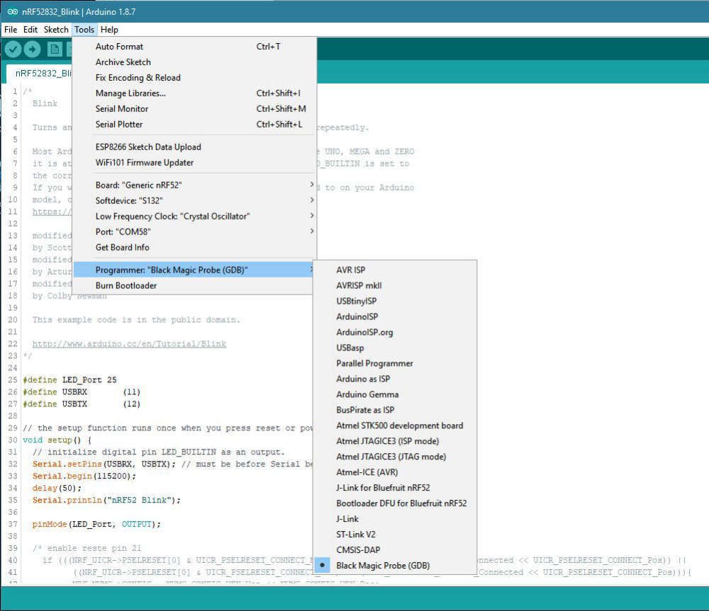
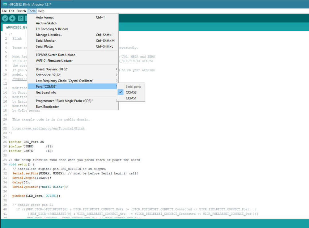
Uploading the bkink example with the ST-Link V2 works, but there is no serial print, no debug, thus I'm trying the BMP way.Here some setttings from my Arduino IDE (Tools section)
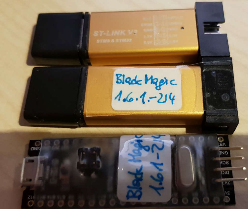
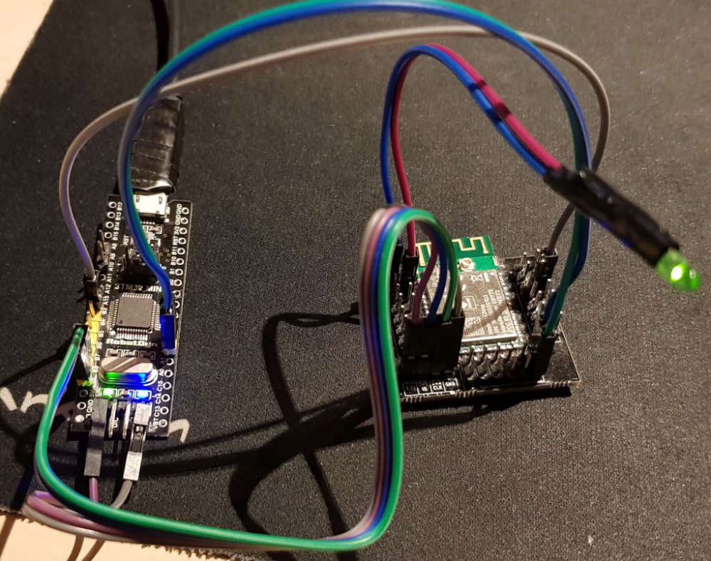
Here are my different BMP modules I have used
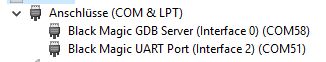
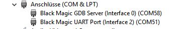
and the COM devices in Win 10
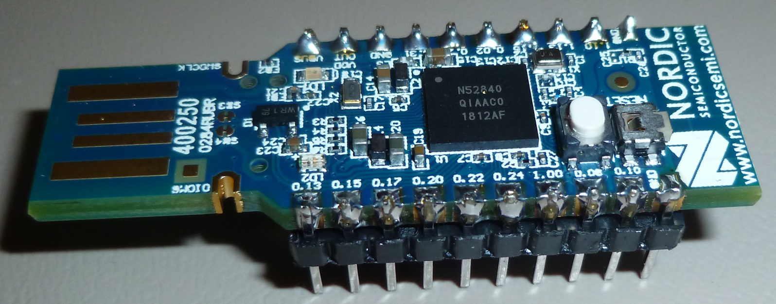
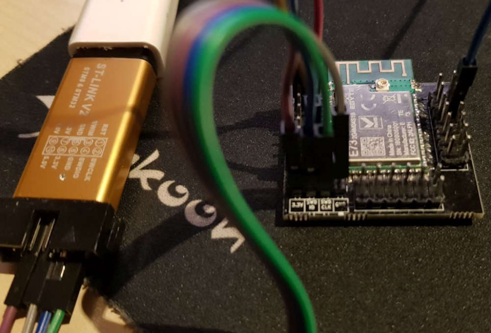
I have tried all kind of driver (using Zadik 2.4), but WInUSB, lisbusbK, libusb ... they all create USB devices only but no COM devices, which Arduino IDE does not "like") only the usbser driver gives me COM devicesand the target device I'm using (which works, when I load the sketch with the ST-Link and select ST-Link in Arduino IDE)
-
@neverdie good discussion, but in order to get my desired solution which is sensor nodes with E-Paper and working with OpenHAB I need I either get the nRF52 modules running with mySensors (ideally just using the Arduino porject and IDE) using the nRF option (I think there is some initial nRF5 support) and using the older nRF24 protocol, or using LoRa with an RFM95 module (which is also supported) or I switch completly to Segger and make a ZigBee V3.0 solution (requiring a ZigBee gateway for OpenHAB). With my new Philips Hue HW version and the new SW firmware upgrade. It is claiming to support ZigBee V3.0 devices which includes also Temp/Hum sensors.
I'm also looking forward for the solution from berkseo where he does exactly that with and nRF52, but that seem to take some time to make it available.
https://www.openhardware.io/view/629/Temperature-and-humidity-sensorverNRF52832E-Ink-display#tabs-instructions -
@neverdie good discussion, but in order to get my desired solution which is sensor nodes with E-Paper and working with OpenHAB I need I either get the nRF52 modules running with mySensors (ideally just using the Arduino porject and IDE) using the nRF option (I think there is some initial nRF5 support) and using the older nRF24 protocol, or using LoRa with an RFM95 module (which is also supported) or I switch completly to Segger and make a ZigBee V3.0 solution (requiring a ZigBee gateway for OpenHAB). With my new Philips Hue HW version and the new SW firmware upgrade. It is claiming to support ZigBee V3.0 devices which includes also Temp/Hum sensors.
I'm also looking forward for the solution from berkseo where he does exactly that with and nRF52, but that seem to take some time to make it available.
https://www.openhardware.io/view/629/Temperature-and-humidity-sensorverNRF52832E-Ink-display#tabs-instructions@heinzv Fair enough.
Probably soon I'll take a crack at doing an OTA DFU with an nRF52840. The good news is that Nordic is reasonably responsive to questions with about a 24 hour turnaround, so that means any sticking points should be resolvable. Failing that I may try writing my own basic OTA uploader.
-
@nagelc Thanks for your response and trying to get me further.
I'm trying to get you as much infos as possible:
I made a couple of screenshots and picture of my environment. Maybe that helps to trace down to the problem.
I followed exactly the instructions from sanseeps Arduino/nRF5 configuration/installation.
Uploading the bkink example with the ST-Link V2 works, but there is no serial print, no debug, thus I'm trying the BMP way.Here some setttings from my Arduino IDE (Tools section)
Here are my different BMP modules I have used
and the COM devices in Win 10
I have tried all kind of driver (using Zadik 2.4), but WInUSB, lisbusbK, libusb ... they all create USB devices only but no COM devices, which Arduino IDE does not "like") only the usbser driver gives me COM devicesand the target device I'm using (which works, when I load the sketch with the ST-Link and select ST-Link in Arduino IDE)
@heinzv For Softdevice, pick None. MySensors doesn't use the Softdevices and I don't think you want it for Generic NRF52 either.
The Low Frequency Clock depends on your board. If it has an external crystal outside the NRF 52, use Crystal Oscillator. Otherwise pick RC Oscillator to use the internal oscillator.
Your BMP ports look correct. In your setup, 58 for the programmer. Use the UART port , 51, to listen to serial debug.
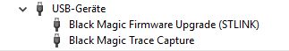
The Black Magic Firmware Upgrade is for use with DFU Util to upgrade the firmware on the probe. I'm not sure what the Trace Capture is. -
@heinzv For Softdevice, pick None. MySensors doesn't use the Softdevices and I don't think you want it for Generic NRF52 either.
The Low Frequency Clock depends on your board. If it has an external crystal outside the NRF 52, use Crystal Oscillator. Otherwise pick RC Oscillator to use the internal oscillator.
Your BMP ports look correct. In your setup, 58 for the programmer. Use the UART port , 51, to listen to serial debug.
The Black Magic Firmware Upgrade is for use with DFU Util to upgrade the firmware on the probe. I'm not sure what the Trace Capture is.@nagelc I have tested both w/ and w/o softdevice, it doesnt make a difference but yes I'll remove it again.
My boards (the E73 module) have an external 32kHz crystal osci for RTC.
In Arduino, you can only select one port. If COM58 is set (for the programmer) then it would open the serial monitor also on that port. However I have tried to use port 51 with another terminal (putty) and it does not connect (I've tried with different baud rates).
I'm not sure but I think (and read) that the second port is only for the SW update of the BMP and not for debugging. Debugging is most likely also on port 58 but for the GDB and not for Arduino, but if it is used (initiated) via Arduino, I could not connect to GDB with a command terminal, so I think the programm has to be started with the command windows and GDB. I've also tested that from that direction and was also not succesfull (I spnt many hours with Google and BMP docu and GDB).
I also don't know how to use the non COM (USB only) devices like the "Trace Capture" as thery are not visible/offered in Arduiono IDE.You're using BMP with Arduino IDE? How are you doing the serial output?
How can you used two different ports in Arduino (there is only one port setting)? -
@nagelc I have tested both w/ and w/o softdevice, it doesnt make a difference but yes I'll remove it again.
My boards (the E73 module) have an external 32kHz crystal osci for RTC.
In Arduino, you can only select one port. If COM58 is set (for the programmer) then it would open the serial monitor also on that port. However I have tried to use port 51 with another terminal (putty) and it does not connect (I've tried with different baud rates).
I'm not sure but I think (and read) that the second port is only for the SW update of the BMP and not for debugging. Debugging is most likely also on port 58 but for the GDB and not for Arduino, but if it is used (initiated) via Arduino, I could not connect to GDB with a command terminal, so I think the programm has to be started with the command windows and GDB. I've also tested that from that direction and was also not succesfull (I spnt many hours with Google and BMP docu and GDB).
I also don't know how to use the non COM (USB only) devices like the "Trace Capture" as thery are not visible/offered in Arduiono IDE.You're using BMP with Arduino IDE? How are you doing the serial output?
How can you used two different ports in Arduino (there is only one port setting)?@heinzv Yes. I'm using with Arduino IDE, but I connect a terminal program (TerraTerm) to the UART com port. You need to do more setup to get the serial out from NRF52832. The easiest way is to use the MyBoardNRF5 board type to select a pin to be TX. But that is a bit much for a blink sketch.
There is yet another usb driver for the Trace and Firmware Update ports. I forget how that is loaded (zadig I think), but you can safely ignore it.
Seems like your setup should just work uploading the sketch on your COM58.For the GDB connection. There is a syntax difference for ports higher than 9. Try this. I had it in my notes, but haven't tried it since my ports are less than 9.
"target extended-remote \.\com58"
-
@heinzv Yes. I'm using with Arduino IDE, but I connect a terminal program (TerraTerm) to the UART com port. You need to do more setup to get the serial out from NRF52832. The easiest way is to use the MyBoardNRF5 board type to select a pin to be TX. But that is a bit much for a blink sketch.
There is yet another usb driver for the Trace and Firmware Update ports. I forget how that is loaded (zadig I think), but you can safely ignore it.
Seems like your setup should just work uploading the sketch on your COM58.For the GDB connection. There is a syntax difference for ports higher than 9. Try this. I had it in my notes, but haven't tried it since my ports are less than 9.
"target extended-remote \.\com58"
@nagelc So everything works now with the BMP using the MyBoardNRF5. At least it supports the nRF52832 (if I'm lucky also the nRF52840) but I started with my barebone 832 modules.
So it upload the sketch and it does also reset and start.
I could also do the connection to the second serial port now with Terra Term and get the Serial.println. Cool.
The secret was, that I created another BMP for my blackpills (I did a couple of tweaks) and connect now the HW serial of the nRF52 to the BMP serial (UART2) and it forwards it via the USB of the BMP to the COM port.The output looks now like yours when I do an upload:
WARNING: Spurious .ci folder in 'MySensors' library
WARNING: Spurious .mystools folder in 'MySensors' library
Build options changed, rebuilding all
Sketch uses 3720 bytes (0%) of program storage space. Maximum is 524288 bytes.
Remote debugging using \.\COM58
Target voltage: unknown
Available Targets:
No. Att Driver
1 Nordic nRF52
2 Nordic nRF52 Access Port
Attaching to Remote target
0x00000ae0 in ?? ()
Reading symbols from nRF52832_Blink.ino.elf...done.
Loading section .text, size 0xe88 lma 0x0
Loading section .ARM.exidx, size 0x8 lma 0xe88
Loading section .data, size 0x74 lma 0xe90
Start address 0x5f8, load size 3844
Transfer rate: 27 KB/sec, 640 bytes/write.
Temporary breakpoint 1 at 0xbc4: file D:\mcdev\arduino\portable\packages\sandeepmistry\hardware\nRF5\0.6.0\cores\nRF5\main.cpp, line 28.
Starting program: C:\Users\internet\AppData\Local\Temp\arduino_build_913185\nRF52832_Blink.ino.elf
Note: automatically using hardware breakpoints for read-only addresses.Temporary breakpoint 1, main ()
at D:\mcdev\arduino\portable\packages\sandeepmistry\hardware\nRF5\0.6.0\cores\nRF5\main.cpp:28
28 {Program complete!
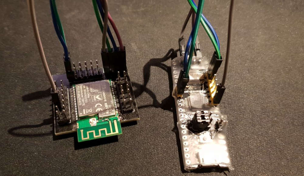
Here is the picture of my BMP and the nRF module:
-
My nRF52832 moduls with MySensors in nRF24 mode seem to work, I have to start another node acting als Gateway and see if they communicate and what distance can be reached in the nRF24 mode.
| / |_ / | ___ _ __ ___ ___ _ __ ___
| |/| | | | _ \ / _ \_ \/ __|/ _ \|_/ __|
| | | | || || | / | | _ \ _ | | _
|| ||_, |/ ___|| ||/_/|| |/
|__/ 2.3.1-beta24 MCO:BGN:INIT NODE,CP=RNNNN---,VER=2.3.1-beta
28 TSM:INIT
30 TSF:WUR:MS=0
31 TSM:INIT:TSP OK
33 TSM:FPAR
40 TSF:MSG:SEND,255-255-255-255,s=255,c=3,t=7,pt=0,l=0,sg=0,ft=0,st=OK:
2048 !TSM:FPAR:NO REPLY
2050 TSM:FPAR
2057 TSF:MSG:SEND,255-255-255-255,s=255,c=3,t=7,pt=0,l=0,sg=0,ft=0,st=OK:
4064 !TSM:FPAR:NO REPLY
4066 TSM:FPAR
4073 TSF:MSG:SEND,255-255-255-255,s=255,c=3,t=7,pt=0,l=0,sg=0,ft=0,st=OK:
6081 !TSM:FPAR:NO REPLY
6083 TSM:FPAR
6090 TSF:MSG:SEND,255-255-255-255,s=255,c=3,t=7,pt=0,l=0,sg=0,ft=0,st=OK:
8098 !TSM:FPAR:FAIL
8099 TSM:FAIL:CNT=1
8101 TSM:FAIL:DIS
8103 TSF:TDI:TPD
18105 TSM:FAIL:RE-INIT
18107 TSM:INIT
18108 TSM:INIT:TSP OK
18110 TSM:FPAR
18117 TSF:MSG:SEND,255-255-255-255,s=255,c=3,t=7,pt=0,l=0,sg=0,ft=0,st=OK:
20125 !TSM:FPAR:NO REPLY
20127 TSM:FPAR
20134 TSF:MSG:SEND,255-255-255-255,s=255,c=3,t=7,pt=0,l=0,sg=0,ft=0,st=OK:
22142 !TSM:FPAR:NO REPLY
22144 TSM:FPAR
22151 TSF:MSG:SEND,255-255-255-255,s=255,c=3,t=7,pt=0,l=0,sg=0,ft=0,st=OK:
24159 !TSM:FPAR:NO REPLY
24161 TSM:FPAR
24168 TSF:MSG:SEND,255-255-255-255,s=255,c=3,t=7,pt=0,l=0,sg=0,ft=0,st=OK:
26176 !TSM:FPAR:FAIL
26177 TSM:FAIL:CNT=2
26179 TSM:FAIL:DIS
26181 TSF:TDI:TPD -
I built the micropython firmware for running on the nRF52840:
Here's the proof:
MicroPython v1.9.4-623-g34af10d2e on 2018-10-05; PCA10056 with NRF52840
Type "help()" for more information.
>>> 1+1
2
>>>
You can download it from here: https://forum.micropython.org/viewtopic.php?f=2&t=5348
-
So, the idea for doing OTA code updates is simple enough: you transmit each line of code and the target assembles it into a string. Then the target executes the string, which updates the code on the target. QED
Here's a notional example of what I mean:
>>> simpleCode="def j(x): return x**2"
>>> simpleCode
'def j(x): return x**2'
>>> exec(simpleCode)
>>> j(5)
25
>>>
You can use whatever radio transport you want, including Nordic's "proprietary radio" that we are all familiar with. There's no reliance on bluetooth or Nordic's DFU. :)
-
@NeverDie great job! I'll definity try it on my holyiot bare modules, but I'm still fighting with the flashing via either the Nordic DK and/or ST-Link v2SO far I was not successfull (I only got it to run with Arduino IDE and BMP, but that is not usable in that case). DK seem not recognize my external nRF52840 and the ST-Link wants some address ranges so I'm trying to get it run with openocd, but that also returns errors. So I'm stuck and wasting many evenings/nights (with Google).
@heinzv Using the DK should be easy. If you want to post how you're wiring your connections to the target, maybe I could help you identify what mistake you are making. Or, if you prefer, you could post to the Nordic support forum, as they would be obligated to help since it's a Nordic product. Or, better yet, do both, because then you'll at least get the ball rolling with Nordic in case you have a defective DK (unlikely, but who knows).
-
@NeverDie thanks for the hints/offer:
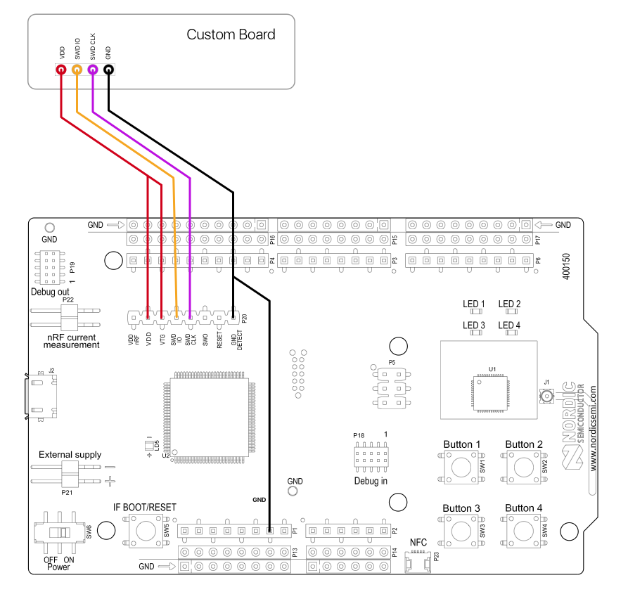
I have connected to the nRF52840 DK via the P20 connector
Here is the wiring setupVDD---> VTG of P20 in DK board
SWDIO--> SWDIO of external board
SWDCLK-->SWDCLK of external Baord
GND DETECT--> GND of external Board
GND--> GND of external baord. -
@NeverDie thanks for the hints/offer:
I have connected to the nRF52840 DK via the P20 connector
Here is the wiring setupVDD---> VTG of P20 in DK board
SWDIO--> SWDIO of external board
SWDCLK-->SWDCLK of external Baord
GND DETECT--> GND of external Board
GND--> GND of external baord. -
@neverdie I admit that I also powered the module via the DK because it takes less than 20mA. I used this connection description:
But I'll try to use a complete an external PS next time and see if it makes a difference.@heinzv Nice picture. Hmmmm..... Seems like your wiring should work. Maybe try VDDnRF instead of VDD? I'm not sure what the difference is, but I think that may have been what I used most recently.
Are you dragging the hex file to the virtual drive on the PC to upload it to the target? If so, what exactly happens when you do? It should be as simple as that.
I'm using Windows 10. What about you? Not sure if the version of Windows has anything to do with it.
It appears that you are using the nRF52832 DK. Correct? What exactly is the target that you are trying to upload to?
One way or another we'll get this thing solved for you. :wink:
-
@NeverDie thanks, appreciate your help as you are far ahead.
Here is my update: I have build 4 nRF52832 boards with the E73 EBYTE modules and two nRF52840 board with the tiny holyiot modules (see picts below).
It seems that by using the wiring shown in my last post, I can flash the 840 boards. I'll also try again one of the working 832 boards later (I'm in business trip the next few days).
But I have a couple of questions to you:
1.) I don't know how to identify which MCU will be flashed. I only see the J-Link adapter in Segger or the board with the Segger Serial in nRFgo Studio. How can I know, that I'm not flashing the DK onboard MCU? Where is this shown, indicated where the flashing will go? That is strange to me. Another example is my sel build Black Magic Probe: It shows which devices are connected to it and you can select one (if multiple are shown in a select - select target 1,2 ...)
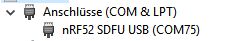
2.) How can I make use of any bootloader (DFU, Serial, USB, OTA, ANT etc.) so that flashing with the DK is not always required? I have not found a good way so far to flash any useful bootloader (I have tried some of the examples). The onyl one which creates a serial devices is the example for the PCA100059 (the USB dongle) which shows a serial device: nRF52 SDFU USB (COM75). HOw to make use of that (I have tried all of the offered programmer als oin Arduino IDE but could not upload/flash my blink sketch)
3.) How to you flash the USB dongle beside using the nRFconnect which requires the compiled image?
Are you also soldering the SWD pins and use them with the Segger and the DK?
4.) When I flashed your micropython (or circuitpython?) for the 840 (my board). How to I connect and use it? My 840 boards have it's own USB port (see topic 2, which shows the nRF52 SDFU port when I flash the one bootloader). When I flash the MP, the ports are gone (how to connect via USB, Serial, Terminal etc.)?I've also tried a couple of other things like a DFU bootloader with a S140 softdevice (as it was recommended by Nordic) but was not sucessful to combine them (the S140 was flashed, but then?)
I have many more questions but I hope we can sort out some of the 1-4. I hope I have described them so that you can follow my thoughts and questions :-)
nrf52840 on DK
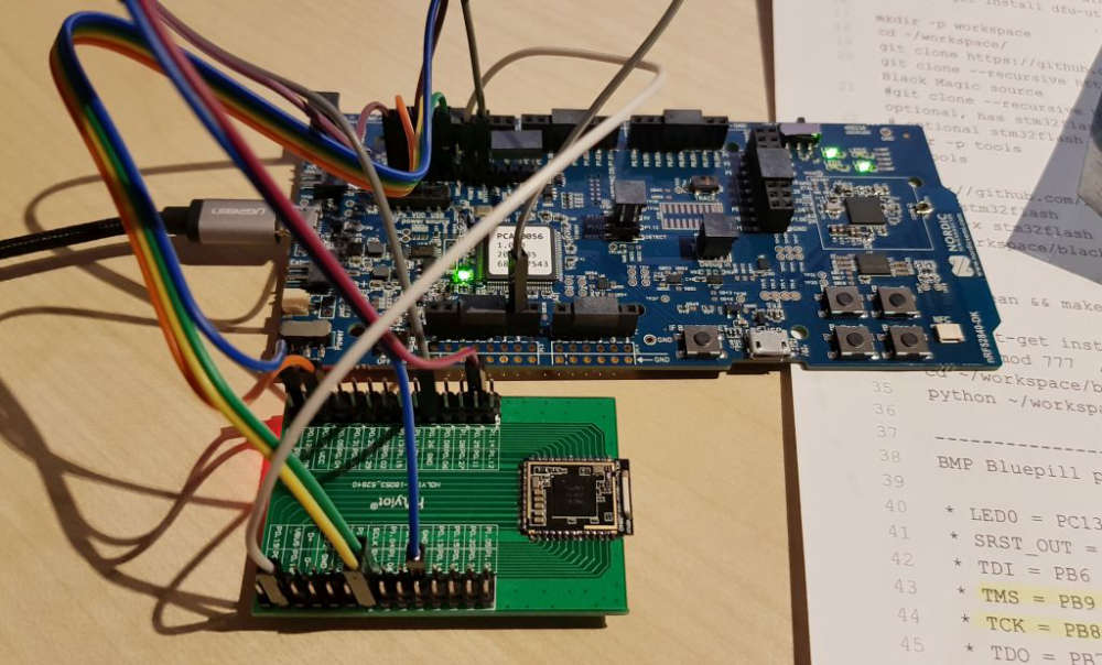
nRF52832 on BMP
-
@NeverDie thanks, appreciate your help as you are far ahead.
Here is my update: I have build 4 nRF52832 boards with the E73 EBYTE modules and two nRF52840 board with the tiny holyiot modules (see picts below).
It seems that by using the wiring shown in my last post, I can flash the 840 boards. I'll also try again one of the working 832 boards later (I'm in business trip the next few days).
But I have a couple of questions to you:
1.) I don't know how to identify which MCU will be flashed. I only see the J-Link adapter in Segger or the board with the Segger Serial in nRFgo Studio. How can I know, that I'm not flashing the DK onboard MCU? Where is this shown, indicated where the flashing will go? That is strange to me. Another example is my sel build Black Magic Probe: It shows which devices are connected to it and you can select one (if multiple are shown in a select - select target 1,2 ...)
2.) How can I make use of any bootloader (DFU, Serial, USB, OTA, ANT etc.) so that flashing with the DK is not always required? I have not found a good way so far to flash any useful bootloader (I have tried some of the examples). The onyl one which creates a serial devices is the example for the PCA100059 (the USB dongle) which shows a serial device: nRF52 SDFU USB (COM75). HOw to make use of that (I have tried all of the offered programmer als oin Arduino IDE but could not upload/flash my blink sketch)
3.) How to you flash the USB dongle beside using the nRFconnect which requires the compiled image?
Are you also soldering the SWD pins and use them with the Segger and the DK?
4.) When I flashed your micropython (or circuitpython?) for the 840 (my board). How to I connect and use it? My 840 boards have it's own USB port (see topic 2, which shows the nRF52 SDFU port when I flash the one bootloader). When I flash the MP, the ports are gone (how to connect via USB, Serial, Terminal etc.)?I've also tried a couple of other things like a DFU bootloader with a S140 softdevice (as it was recommended by Nordic) but was not sucessful to combine them (the S140 was flashed, but then?)
I have many more questions but I hope we can sort out some of the 1-4. I hope I have described them so that you can follow my thoughts and questions :-)
nrf52840 on DK
nRF52832 on BMP
@heinzv said in Everything nRF52840:
@NeverDie thanks, appreciate your help as you are far ahead.
Here is my update: I have build 4 nRF52832 boards with the E73 EBYTE modules and two nRF52840 board with the tiny holyiot modules (see picts below).
It seems that by using the wiring shown in my last post, I can flash the 840 boards. I'll also try again one of the working 832 boards later (I'm in business trip the next few days).
But I have a couple of questions to you:
1.) I don't know how to identify which MCU will be flashed. I only see the J-Link adapter in Segger or the board with the Segger Serial in nRFgo Studio. How can I know, that I'm not flashing the DK onboard MCU? Where is this shown, indicated where the flashing will go? That is strange to me. Another example is my sel build Black Magic Probe: It shows which devices are connected to it and you can select one (if multiple are shown in a select - select target 1,2 ...)If it's wired corectly, then only the external board gets flashed.
2.) How can I make use of any bootloader (DFU, Serial, USB, OTA, ANT etc.) so that flashing with the DK is not always required? I have not found a good way so far to flash any useful bootloader (I have tried some of the examples). The onyl one which creates a serial devices is the example for the PCA100059 (the USB dongle) which shows a serial device: nRF52 SDFU USB (COM75). HOw to make use of that (I have tried all of the offered programmer als oin Arduino IDE but could not upload/flash my blink sketch)
I don't know.
3.) How to you flash the USB dongle beside using the nRFconnect which requires the compiled image?
Are you also soldering the SWD pins and use them with the Segger and the DK?Yes.
4.) When I flashed your micropython (or circuitpython?) for the 840 (my board). How to I connect and use it? My 840 boards have it's own USB port (see topic 2, which shows the nRF52 SDFU port when I flash the one bootloader). When I flash the MP, the ports are gone (how to connect via USB, Serial, Terminal etc.)?
So far I've only flashed MP to the 832 and 840 DK's. In those instances, you can do serial IO over the USB connection using putty or similar terminal.
I've also tried a couple of other things like a DFU bootloader with a S140 softdevice (as it was recommended by Nordic) but was not sucessful to combine them (the S140 was flashed, but then?)
I have many more questions but I hope we can sort out some of the 1-4. I hope I have described them so that you can follow my thoughts and questions :-)
-
Howdy y'all first off thanks @NeverDie for this thread, I spent a good time lurking at these NRF52 posts and learned and re-learned a few things here and there.
I've built an E73 NRF52832 PCB and successfully did a blink using Espruino and Adafruit's Bluefruit FW for Arduino and just noticed the $10 CAD E73-2G4M08S1C (NRF52840) back in-stock (as of October 8). I am in the process of designing a pcb board layout for it but in the meantime thought that the community might find the following useful if you plan on designing/using these modules:
-
E73-2G4M08S1C and other footprints in the same 'family' are readily available in Altium Designer format here: http://www.cdebyte.com/en/data-download.aspx?id=356&pid=202
-
Library.io allows you to convert '.pcblib' / altium files to an Eagle Library format, you just need to specify the Symbol and Package, from here you can convert to KiCad or similar I'd reckon but have not used KiCad enough to verify this. This saved me a lot of time.
In case someone was wondering: I've had no issues using the J-Link Edu Mini with the NRF52832, will update here when I get to the NRF52840.
Just starting my own NRF journey and thought to add this here in case someone is looking for E73 module specifics WRT NRF52832/NRF52840 .
-