Everything nRF52840
-
@NeverDie I think you need to hold it, but it looks there is "coded" holes/slots for helping and correct positioning.
@monte
@monte said in Everything nRF52840:haven't you noticed that mysensors' community which is represented mostly by this forum has become more than just an arduino library?
Hmm, I haven't.. so what's more? Has MySensors been forked to another platform?
@monte said in Everything nRF52840:
People share on this forum many projects that has only mediate connection to mysensors, if any. And many of users of the library in it's current form have outgrowing some of it's limitations, so naturally they will try to find a solution to overcome them and then share with others on this forum.
I'm not the last on bleeding edge, but I didn't notice many mediate connections..Which limitations have been hacked? maybe on the forum, not same on git I think. Thx to PR contributors. But apart from mysensors team, especially one very active contributor that we can thx ;) it's rather rare.
@monte said in Everything nRF52840:
I don't see nothing wrong for mysensors platform to evolve and adopt modern standards and/or protocols. And even if 15.4 is not suitable or just a replacement of mysensors protocol
Not in scope and not supported by mysensors team to switch to a standard, as mysensors is still about its own stack. It's like if you wanted to mix zigbee&mysensors logics (doesn't make sense). So 15.4 is a replacement. Maybe read about it. I'm telling this because I played and playing with 15.4+another mcu, and comparing stacks.. whether switching stack or not. If not, what could be improved, logics to add to mysensors etc.
@monte said in Everything nRF52840:
I think there are people here that will find it useful to read about it. Correct me if I'm wrong but there is no rule against discussing other protocols than mysensors on this forum.
you're right. no rule on this, free to talk. But I preferred to be precise for newcomers who may get confused when reading about nrf52840 in mysensors, that there is no support from team for others stacks, and non-arduino.
Lot of "noobs" don't know what means a rf stack exactly, what logics inside etc, they simply want to use MySensors because it's easy to use, especially when non former dev. That's what would expect someone discovering nrf52840 is supported in MySensors. So this gets completely confusing, external toolchains and using others rf stacks etc.. might end in hundreds of posts with just a few mysensors relevant infos (good luck for newcomers)wasting my time, I won't disturbe your experiments anymore ;)
Good luck and feel free to improve MySensors of course! -
@NeverDie This is a bit of a side-question but to what degree could Arduino's Bluetooth support fulfill the role MySensors plays?
In theory it seems Bluetooth could be a useful smart home communications platform:
- Just like MySensors, Zigbee, Z-wave, it avoids using the IP stack, and generates a separate network for smart devices. This lowers risk to user's home network.
- Lower energy than WiFi. Lower energy than NRF24 too?
- The killer app: it's built into smartphones, tablets and Raspberry Pi's already. No need for an extra dongle.
What I don't know is
- To what extent Bluetooth has useful smart home profiles
- To what extent Arduino devices could present themselves as smart home devices using those profiles.
- To what extent older Bluetooth chips can work with newer device profiles (it would seem a software upgrade should be enough?)
Maybe this should be a separate post :-)
@alowhum said in Everything nRF52840:
To what extent Bluetooth has useful smart home profiles
To what extent Arduino devices could present themselves as smart home devices using those profiles.Well, the BLE has a lot in common with REST. You have to have one or more central devices (clients) which will query peripherals with sensors and actuators (servers). Communication is P2P, but broadcasting is also supported to some extent (various beacons are well known examples).
If thinking about it like a RESTful sevice, there is a number of API which were standardized. They call it profile, like in, for example, the Heart Rate Profile. The standard just assures that any heart rate monitoring device will talk the same protocol as any other one - that's it. I don't think there is many standard profiles for smart home devices (if any). At the same time, there is the Project Connected Home IP.
Of course, there is nothing which may prevent somebody to implement his own interface. If it will be successful enough, it will be later possible to contact the SIG group and promote it to a standard.
Please also note, that for serious boradcasting there is the Mesh. In a nutshell it works similarly to Ethernet switches. Interesting side effect is that it's possible to build a Mesh network physically wide thus delivering packets over long distances. Of course, if you want to go global, the IPv6 will be the right choice to go. It will require a standalone BLE enable router though - it will connect the devices to the Internet.
To what extent older Bluetooth chips can work with newer device profiles (it would seem a software upgrade should be enough?)
As long as they support Bluetooth Low Energy - i.e. version 4.2 or above.
-
@monte said in Everything nRF52840:
Found this repo: https://github.com/xriss/nrfx
Gone already ...
@NeverDie said in Everything nRF52840:
@monte Is PineTime the best of the currently available nRF52 watch options? If so, since it's offered at $24.99, I think I may want to order one.
A very interesting project, too bad they are using NRF52832 and not NRF52840, the max SPI speed on ...32 is too low (8MHz) and I'm afraid the LCD refresh will be annoyingly slow :(
@Nca78 said in Everything nRF52840:
A very interesting project, too bad they are using NRF52832 and not NRF52840, the max SPI speed on ...32 is too low (8MHz) and I'm afraid the LCD refresh will be annoyingly slow
It might be also interesting to employ the Sharp LS012B7DD06 which is a round 240x240 6-bit color memory display consuming 11 µW in static mode. It will be far away of the PineTime's $25, but with the CryptoCell, NFC and other stuff it might worth it.
Shall we create a repo? ;-)
-
@scalz said in Everything nRF52840:
@NeverDie I think you need to hold it, but it looks there is "coded" holes/slots for helping and correct positioning.
You may want to use TC clip for long-time debugging or odd boards like this:

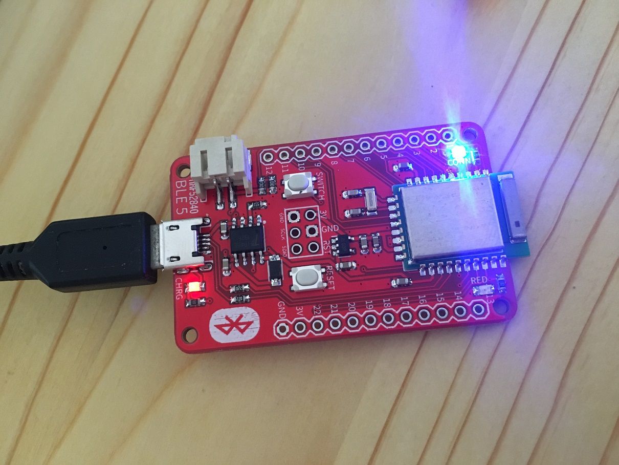
The idea I settled on is using a micro-usb connector to make my programming connections. It's cheap and the footprint is small.
I've posted about it previously, but it got a lot of pushback over the concern that people will think it's a functional usb and plug it into a charger. However, I won't be forgetting, so it hasn't been a problem for me. I suppose that if I were to hand a device over to a layman, I'd probably plug the connector with a drop of superglue (either that or simply de-solder it), since a layman wouldn't be programming it anyway.
That said, micro-usb connectors aren't super-easy to solder, so I'd like to find something equally tiny that is.
-
The idea I settled on is using a micro-usb connector to make my programming connections. It's cheap and the footprint is small.
I've posted about it previously, but it got a lot of pushback over the concern that people will think it's a functional usb and plug it into a charger. However, I won't be forgetting, so it hasn't been a problem for me. I suppose that if I were to hand a device over to a layman, I'd probably plug the connector with a drop of superglue (either that or simply de-solder it), since a layman wouldn't be programming it anyway.
That said, micro-usb connectors aren't super-easy to solder, so I'd like to find something equally tiny that is.
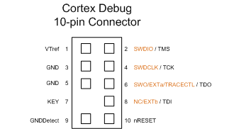
@NeverDie For something which is very generic I'd vote for the Cortex 10 pin debug connector. It is as small as Micro USB, very cheap (you may also do not install the connector itself and left that for other users), versatile (may be angled or straight) and - what's very important - it is standard. And, while in this topic, the bonus: it's compatible out of the box with the nRF52 devkits.
-
@NeverDie For something which is very generic I'd vote for the Cortex 10 pin debug connector. It is as small as Micro USB, very cheap (you may also do not install the connector itself and left that for other users), versatile (may be angled or straight) and - what's very important - it is standard. And, while in this topic, the bonus: it's compatible out of the box with the nRF52 devkits.
@Mishka said in Everything nRF52840:
I'd vote for the Cortex 10 pin debug connector
You mean like the connector on this?
https://www.openhardware.io/view/510/Multi-Sensor-TempHumidityPIR-LeakMagnetLightAccelThat's what I started with. But I really only need 5 pins: SWD, SWO, Tx, Rx, and GND, so 5 of the 10 pins are wasted.
I went with the boxed connector, which is huge, to prevent plugging it in wrong. I probably should have gone with the non-boxed connector. Even so, it's still huge.
I could probably get by with just 4 pins by dropping the Rx pin. Thinking back on it now, I don't think I ever actually used the Rx connection. I've definitely used the Tx though for serial print debugging.
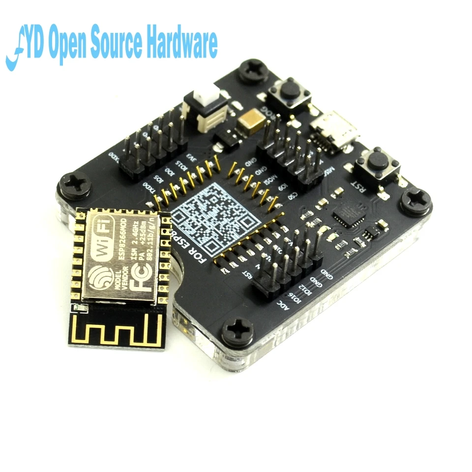
I think the easiest/best idea might be just using 4 castellated pads and pressing up against those with a side connector, similar to what TC's edge connector does or what an esp8266 burner does (but ideally with closer spacing):
 )
) -
@Mishka said in Everything nRF52840:
I'd vote for the Cortex 10 pin debug connector
You mean like the connector on this?
https://www.openhardware.io/view/510/Multi-Sensor-TempHumidityPIR-LeakMagnetLightAccelThat's what I started with. But I really only need 5 pins: SWD, SWO, Tx, Rx, and GND, so 5 of the 10 pins are wasted.
I went with the boxed connector, which is huge, to prevent plugging it in wrong. I probably should have gone with the non-boxed connector. Even so, it's still huge.
I could probably get by with just 4 pins by dropping the Rx pin. Thinking back on it now, I don't think I ever actually used the Rx connection. I've definitely used the Tx though for serial print debugging.
I think the easiest/best idea might be just using 4 castellated pads and pressing up against those with a side connector, similar to what TC's edge connector does or what an esp8266 burner does (but ideally with closer spacing):
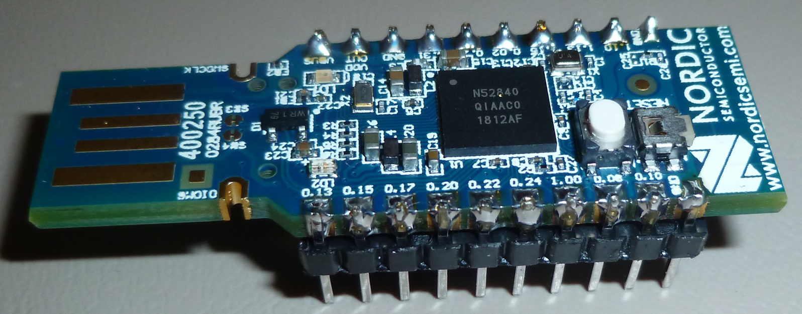
)@NeverDie That's right. You may want to use open version which is much smaller indeed.
Also, for nRF52 only three pins are required: SWDIO, SWDCLK, and VTref. All the three are very conveniently located in close proximity on pins 2, 4 and 1:
Such, for a tiny custom board a 2x2 pin header, 1.27 pitch can be used w/o breaking compatibility.
-
@NeverDie That's right. You may want to use open version which is much smaller indeed.
Also, for nRF52 only three pins are required: SWDIO, SWDCLK, and VTref. All the three are very conveniently located in close proximity on pins 2, 4 and 1:
Such, for a tiny custom board a 2x2 pin header, 1.27 pitch can be used w/o breaking compatibility.
@Mishka How about this?
https://www.amazon.com/CQRobot-Programmer-Testing-Support-Programmer/dp/B07BWFJL31Either 4 pads on one side or 2 pads on each side of the PCB. Very inexpensive. Not sure if they make a 4 pin clip, but if so, that would be ideal.
Maybe if instead of pads you went for 4 through-holes it would even self-align?
-
This is quite clever:
https://www.youtube.com/watch?v=xgLEhTSYqL4If you simply stagger the through-holes then a regular block of header pins will fit through and hold itself in place. No pogo pins required.
-
This is quite clever:
https://www.youtube.com/watch?v=xgLEhTSYqL4If you simply stagger the through-holes then a regular block of header pins will fit through and hold itself in place. No pogo pins required.
@NeverDie said in Everything nRF52840:
If you simply stagger the through-holes then a regular block of header pins will fit through and hold itself in place. No pogo pins required.
I'm not so sure about the reliability of this ... It's not very difficult to make an adapter using pogo pins, you just need to use 2 similar pcbs to align them properly.
Another option is to use smaller headers (2mm or better 1.27 mm) and an adapter from selected spacing to 2.54mm header: cheap and compact connector for the board, cheap adapter and reliable connection.
For example on these adapters you can solder a SMD header on the 1.27mm spaced side and have 2.54mm connectors. You just need to have the opposite genre 1.27mm header on the board and you're done.
https://www.aliexpress.com/item/32855731928.html -
@Mishka How about this?
https://www.amazon.com/CQRobot-Programmer-Testing-Support-Programmer/dp/B07BWFJL31Either 4 pads on one side or 2 pads on each side of the PCB. Very inexpensive. Not sure if they make a 4 pin clip, but if so, that would be ideal.
Maybe if instead of pads you went for 4 through-holes it would even self-align?
@NeverDie
There is an article on hackaday about this type of clamp that even has a KiCAD footprint. I bought one of the clips, but haven't tried it out yet.
https://hackaday.io/project/165917-soicbite-programmingdebug-connector-footprintI also tried this one from Adafruit;
https://www.adafruit.com/product/4048
small, jlink-mini compatible, and polarized.So far, my preferrred solution is a 6 pin jst-sh connector.
small. 3v3, gnd, swdio, swclk, tx, rx
and polarized.My old eyes get tired of confirming I have the pins on in the right direction. Polarization is really nice.
-
@NeverDie said in Everything nRF52840:
If you simply stagger the through-holes then a regular block of header pins will fit through and hold itself in place. No pogo pins required.
I'm not so sure about the reliability of this ... It's not very difficult to make an adapter using pogo pins, you just need to use 2 similar pcbs to align them properly.
Another option is to use smaller headers (2mm or better 1.27 mm) and an adapter from selected spacing to 2.54mm header: cheap and compact connector for the board, cheap adapter and reliable connection.
For example on these adapters you can solder a SMD header on the 1.27mm spaced side and have 2.54mm connectors. You just need to have the opposite genre 1.27mm header on the board and you're done.
https://www.aliexpress.com/item/32855731928.html@Nca78 Yup, I too would worry a bit about the long-term repeatability of the staggered pin approach: after you hook it up a few times, maybe the metal on the throughhole would have scraped off due to the friction fit?
I was thinking that on an "as small as possible" type of board like on Mishka's current project that the castellated connection would have the smallest footprint. On a larger board where space doesn't matter, then, yeah, I would go for some kind of pinned connection. For instance, on my 10 year motion detector, the board size is huge due to just the batteries, so there is plenty of free space to plunk down a connector:
https://www.openhardware.io/view/499/10-years-wireless-PIR-Sensor-on-just-one-set-of-3-AAs
Yet, when it came to mount it in a case, that connector got in the way, and I had to redesign it to use the usb connector that everybody but me seemed to hate on the backside, fitted between the batteries. I suppose I could have used some kind of edge pin connector though if it were small enough.
It would be fun to make a board the same dimensions as an esp8266 or esp32 or wroom module so that I could use one of the test/burner jigs that's designed for them to make the castellated edge connections.
-
@NeverDie
There is an article on hackaday about this type of clamp that even has a KiCAD footprint. I bought one of the clips, but haven't tried it out yet.
https://hackaday.io/project/165917-soicbite-programmingdebug-connector-footprintI also tried this one from Adafruit;
https://www.adafruit.com/product/4048
small, jlink-mini compatible, and polarized.So far, my preferrred solution is a 6 pin jst-sh connector.
small. 3v3, gnd, swdio, swclk, tx, rx
and polarized.My old eyes get tired of confirming I have the pins on in the right direction. Polarization is really nice.
@nagelc said in Everything nRF52840:
There is an article on hackaday about this type of clamp that even has a KiCAD footprint. I bought one of the clips, but haven't tried it out yet.
https://hackaday.io/project/165917-soicbite-programmingdebug-connector-footprintI couldn't find where to buy that soic bite. Is it even for sale anymore?
-
On the other hand, the JST-XSR connector might not be a bad way to go. At 0.6mm pitch, a 4 wire connector is just 3mm wide:
http://www.jst-mfg.com/product/pdf/eng/eXSR.pdf?5e312adac5a05
It's seems very hard to find for sale though.AFAIK, it's the smallest jst connector there is.
-
@nagelc said in Everything nRF52840:
There is an article on hackaday about this type of clamp that even has a KiCAD footprint. I bought one of the clips, but haven't tried it out yet.
https://hackaday.io/project/165917-soicbite-programmingdebug-connector-footprintI couldn't find where to buy that soic bite. Is it even for sale anymore?
@NeverDie I don't think that SOICbite has ever been sold. It's just a conventional SOIC-8 test clip, that may need some modification, like filing away some of the plastic in front of the hinge or at the tip. I like the idea of this method because, apart from having a small footprint, they are super cheap (even less than 2 USD/EUR incl. shipping from China, like this one) and it doesn't require additional parts for every single PCB for a one-time job.
I'm currently designing a PCB (not nRF52840-related though) with the SOICbite connector on it and have some clips on order, to see how well it works. Might take a while until I reveice them, but I can report back as soon as I tested them.
-
hey guys. I'm testing couple of nrf52840 modules. so far i was able to test raytac mdbt50q ipex and e73-2G4M08S1C modules with basic rssi value.
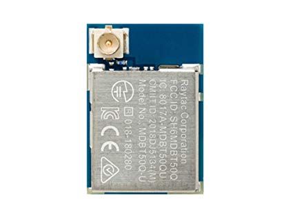
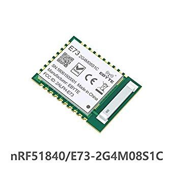 so far ipex version looks abit better but at a cost of external cable and antenna where e73-2G4M08S1C is compact and difference is not that significant.
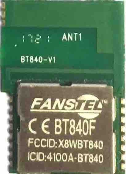
i later saw fanstel products, particularly interested in BT840F model because reported range is significantly better than the BT840 model and the only difference is the antenna design between them.
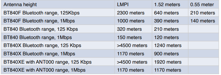
Considering this difference 840F might be way better than the e73-2G4M08S1C. Has anyone able to compare them or test them directly? -
hey guys. I'm testing couple of nrf52840 modules. so far i was able to test raytac mdbt50q ipex and e73-2G4M08S1C modules with basic rssi value.
so far ipex version looks abit better but at a cost of external cable and antenna where e73-2G4M08S1C is compact and difference is not that significant.
i later saw fanstel products, particularly interested in BT840F model because reported range is significantly better than the BT840 model and the only difference is the antenna design between them.
Considering this difference 840F might be way better than the e73-2G4M08S1C. Has anyone able to compare them or test them directly?@orhanyor I compared the Fanstel BT840F to the Ebyte with the trace antenna, and the Fanstel was better. I expect the trace anenna is better than the chip antenna on the module that you referred to, so by the transitive property of inequality, I expect the Fanstel would be better than it.
-
@orhanyor I compared the Fanstel BT840F to the Ebyte with the trace antenna, and the Fanstel was better. I expect the trace anenna is better than the chip antenna on the module that you referred to, so by the transitive property of inequality, I expect the Fanstel would be better than it.
@NeverDie thanks for the reply i hope to try them in the future. Best option is definitely something like BT840X or another nrf52840 or 32 with PA/LNA module it needs to be implemented with a code. i found this https://devzone.nordicsemi.com/nordic/nordic-blog/b/blog/posts/pa-lna-support-in-s132 in nordic forums but im not sure how it can be implemented into an arduino environment.
I actually added this code to an arduino sketch and it compiled without an issue but I cant tell if it will work without having a module with PA. -
@orhanyor I compared the Fanstel BT840F to the Ebyte with the trace antenna, and the Fanstel was better. I expect the trace anenna is better than the chip antenna on the module that you referred to, so by the transitive property of inequality, I expect the Fanstel would be better than it.
@NeverDie also according to this post when TX/RX pins are defined softdevice handles them automatically. https://devzone.nordicsemi.com/f/nordic-q-a/40504/nrf52840-and-pa
But if you have more control in your FEM like in BT840X with SKY66112 you need to control 2-3 more pins in your code. nRF24 modules mostly use RFX2401C its quite simple with only TX/RX pins and it works quite well may be it will pair nicely with nrf52 modules only if we could configure the code for arduino. -
I also designed this 2 layer breakout board with a much bigger inverted F antenna design for the nrf52840, ive put BT840 to compare the antenna size. (still needs some touch ups here and there)
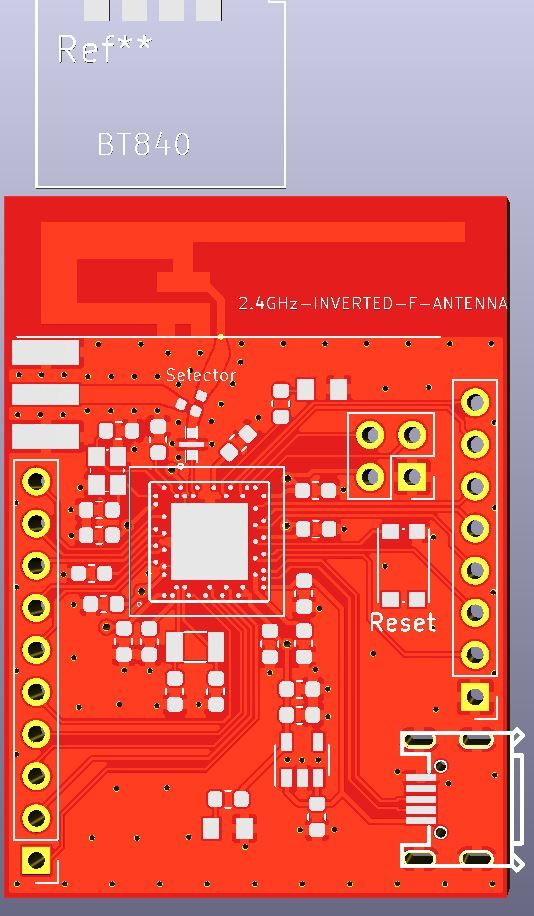
bottom layer has a good ground layer for the antenna and i believe its going to perform better but just to be sure theres a SMA option for external antenna aswell which can be selected with the 0 ohm resistor.
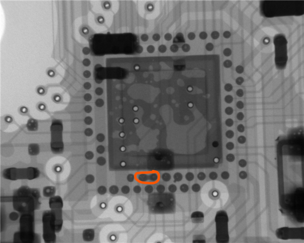
nordic specialist approved it and i will probably give it a try just to compare the antenna performance. My only concern is how hard soldering is going to be. if you noticed i removed the pins who are next to each other(i left some because they are mandatory like d+ - swclk etc..) and left the diagonal ones in order to reduce the chance of possible solder bridges. as you can see from the picture there are reports about solder bridges detected with expensive xray machines which i dont have :) so, fewer the pin count less probability for failure.
on the other hand ebyte nrf52840 e73 modules even with the bottom pads are really easy to solder without a probability to bridge anything and cause issues because bottom pad to pad distance is very generous, im really happy with that.