💬 EFEKTA Temp&Hum sensor(ver. nRF52 )+E-Ink display
-
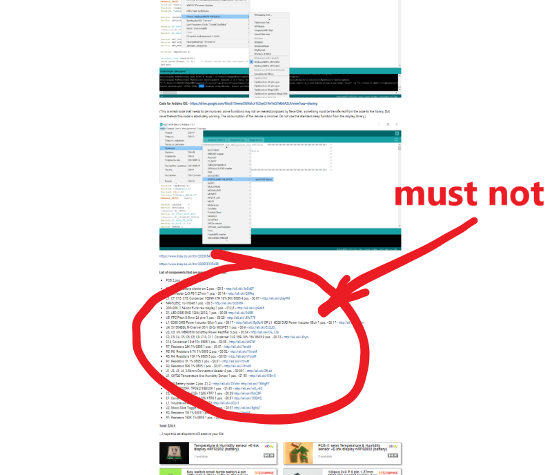
The project became closed. Reason: I previously placed links to all the necessary components for this device(see screenshot). This allowed me to earn quite a bit on the affiliate program. This allowed me a bit to recoup the costs, they are not small. The site administration considers this type of earnings unacceptable.
-
The project became closed. Reason: I previously placed links to all the necessary components for this device(see screenshot). This allowed me to earn quite a bit on the affiliate program. This allowed me a bit to recoup the costs, they are not small. The site administration considers this type of earnings unacceptable.
@berkseo Seriously!!!!!!!!!!!!! It cannot be true!!! I have just ordered PCBs and all needed stuff to assemble it, and now the code is gone!!! Please post the code again, or make it available on alternative sites.. please. It is hundreds of dollars to waste otherwise!
-
@berkseo Seriously!!!!!!!!!!!!! It cannot be true!!! I have just ordered PCBs and all needed stuff to assemble it, and now the code is gone!!! Please post the code again, or make it available on alternative sites.. please. It is hundreds of dollars to waste otherwise!
@magpern said in 💬 EFEKTA Temp&Hum sensor(ver. nRF52832 )+E-Ink display:
Seriously!!!!!!!!!!!!! It cannot be true!!! I have just ordered PCBs and all needed stuff to assemble it, and now the code is gone!!! Please post the code again, or make it available on alternative sites.. please. It is hundreds of dollars to waste otherwise!
The project will remain open, like others. I was in a bad mood that day:)... The rules of the site administration are reasonable, and the decision to open the project was mine.
Code for Arduino IDE - https://drive.google.com/file/d/13wmxCt9XehJr1E2eyG1RnYsQTMb9A2LR/view?usp=sharing
-
development continues...
-
@berkseo said in 💬 EFEKTA Temp&Hum sensor(ver. nRF52832 )+E-Ink display:
@magpern said in 💬 EFEKTA Temp&Hum sensor(ver. nRF52832 )+E-Ink display:
Seriously!!!!!!!!!!!!! It cannot be true!!! I have just ordered PCBs and all needed stuff to assemble it, and now the code is gone!!! Please post the code again, or make it available on alternative sites.. please. It is hundreds of dollars to waste otherwise!
The project will remain open, like others. I was in a bad mood that day:)... The rules of the site administration are reasonable, and the decision to open the project was mine.
Code for Arduino IDE - https://drive.google.com/file/d/13wmxCt9XehJr1E2eyG1RnYsQTMb9A2LR/view?usp=sharing
Thank you! You scared me big time!
Bad ting without links is that eg. clock button 2 pcs... there are millions of clock buttons and to pick the right one with out a link.. well, almost impossible.Thanks again!
-
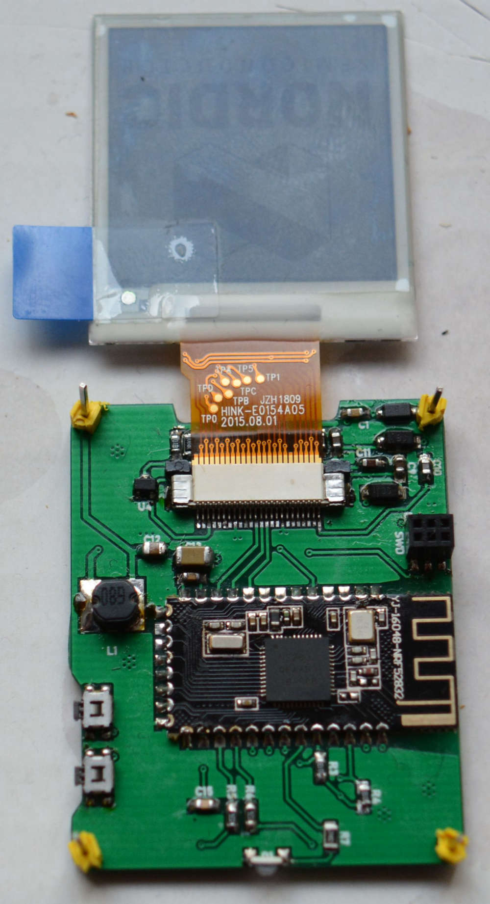
@berkseo I have continued to work on the new PCB's und have oredered some 603 resistors und condensors. I have checked all of the parts and the soldering but did not get the one PCB to displays something. The program runs und I see the LED flashing and also the log looks normal.
A build a second PCB and this one shows the intro graphics but with a grey background and then it stops showing something. No idea what goes wrong.
-
@berkseo I have continued to work on the new PCB's und have oredered some 603 resistors und condensors. I have checked all of the parts and the soldering but did not get the one PCB to displays something. The program runs und I see the LED flashing and also the log looks normal.
A build a second PCB and this one shows the intro graphics but with a grey background and then it stops showing something. No idea what goes wrong.
@heinzv
I apologize that long did not answer. Did you solve the problem? I noticed that the inductance is small (it seemed to me). You should also check for solder connectors ribbon cable. Perhaps not all contacts are soldered and some contact lies on the PCB is not soldered. I had once, it was not well soldered contact pin on display connector . -
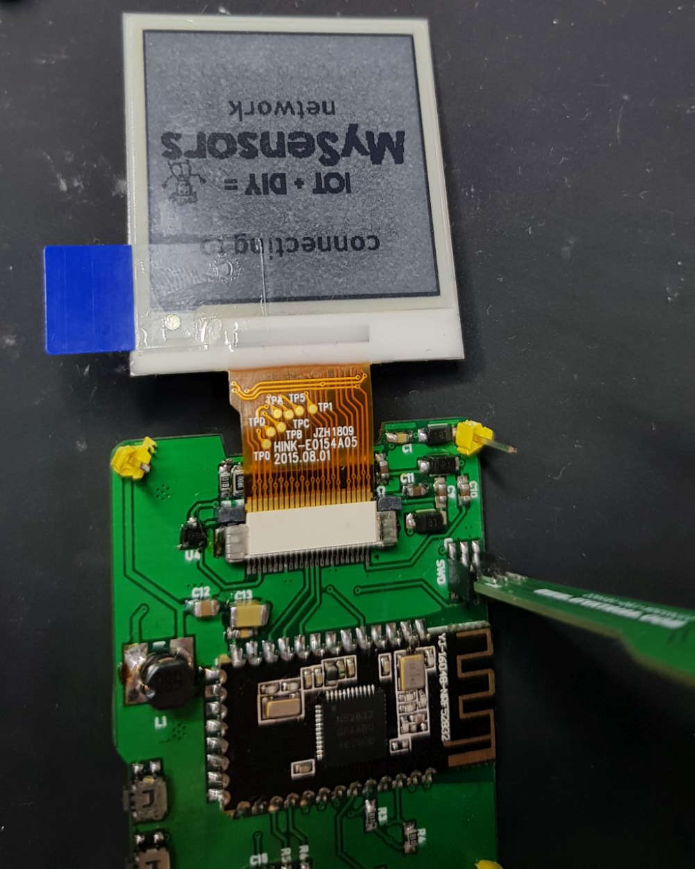
@berkseo no I have not solved the problem yet. I 'll take another picture with higher resolution tomorrow and post it here.
The inductance has the value which is specifiied (I think 68uH). I have all ordered by the links provided.
I have checked the soldering and resolved a few times. I think all pins shall be soldered, but I can verify it again. That was also my first thought and checked the ribbon cable over and over again. -
hey @berkseo these look amazing, any estimate when they might be available again as assembled unit?
Any estimate on how long the battery lasts, with lats say update every 15min?
Could these be updated OTA somehow (or directly perhaps)?
I would like to have option to change layout, or perhaps add some other values to it maybe.
They look amazing, I would like several of these in each room for various things displayed -
@berkseo @heinzv I finally got around to solder one of these together. It was not easy, placing the components was kind of a guessing game, but I think I got it right. When I put two batteries in and turn it on there is a buzzing noise, maybe normal? Anyway... I never realized programming this thing would be a problem.
What equipment is needed to program it? I don't recognize the labeling on the pcb (gnd/vcc sdo/sclk rx/tx)
-
@berkseo @heinzv I finally got around to solder one of these together. It was not easy, placing the components was kind of a guessing game, but I think I got it right. When I put two batteries in and turn it on there is a buzzing noise, maybe normal? Anyway... I never realized programming this thing would be a problem.
What equipment is needed to program it? I don't recognize the labeling on the pcb (gnd/vcc sdo/sclk rx/tx)
@berkseo is the device programmed when output says this?
Open On-Chip Debugger 0.10.0-dev-00254-g696fc0a (2016-04-10-10:13)
Licensed under GNU GPL v2
For bug reports, read
	http://openocd.org/doc/doxygen/bugs.html
debug_level: 0
0x4000
adapter speed: 10000 kHz
nrf52.cpu: target state: halted
target halted due to debug-request, current mode: Thread
xPSR: 0x01000000 pc: 0xfffffffe msp: 0xfffffffc
** Programming Started **
auto erase enabled
nrf52.cpu: target state: halted
target halted due to breakpoint, current mode: Thread
xPSR: 0x61000000 pc: 0x2000001e msp: 0xfffffffc
wrote 102400 bytes from file C:\Users\eu1391\AppData\Local\Temp\arduino_build_38086/epd1in54-demo.ino.hex in 2.178483s (45.904 KiB/s)
** Programming Finished **
** Verify Started **
nrf52.cpu: target state: halted
target halted due to breakpoint, current mode: Thread
xPSR: 0x61000000 pc: 0x2000002e msp: 0xfffffffc
verified 100668 bytes in 0.296666s (331.378 KiB/s)
** Verified OK **
** Resetting Target **
shutdown command invoked
The only thing happening when I turn it on, is that the LED flashed once. Then occasionally the LED flashed sporadically.
The e-paper is just white.Questions?
Can you power the board from another source then the battery pcb?
The board needs to be powered when programming it, right? I'm using a ST-LINK V2 with the SWD pins connected.
How do you debug the board? I use Arduino IDE -
@berkseo is the device programmed when output says this?
Open On-Chip Debugger 0.10.0-dev-00254-g696fc0a (2016-04-10-10:13)
Licensed under GNU GPL v2
For bug reports, read
	http://openocd.org/doc/doxygen/bugs.html
debug_level: 0
0x4000
adapter speed: 10000 kHz
nrf52.cpu: target state: halted
target halted due to debug-request, current mode: Thread
xPSR: 0x01000000 pc: 0xfffffffe msp: 0xfffffffc
** Programming Started **
auto erase enabled
nrf52.cpu: target state: halted
target halted due to breakpoint, current mode: Thread
xPSR: 0x61000000 pc: 0x2000001e msp: 0xfffffffc
wrote 102400 bytes from file C:\Users\eu1391\AppData\Local\Temp\arduino_build_38086/epd1in54-demo.ino.hex in 2.178483s (45.904 KiB/s)
** Programming Finished **
** Verify Started **
nrf52.cpu: target state: halted
target halted due to breakpoint, current mode: Thread
xPSR: 0x61000000 pc: 0x2000002e msp: 0xfffffffc
verified 100668 bytes in 0.296666s (331.378 KiB/s)
** Verified OK **
** Resetting Target **
shutdown command invoked
The only thing happening when I turn it on, is that the LED flashed once. Then occasionally the LED flashed sporadically.
The e-paper is just white.Questions?
Can you power the board from another source then the battery pcb?
The board needs to be powered when programming it, right? I'm using a ST-LINK V2 with the SWD pins connected.
How do you debug the board? I use Arduino IDEIt sure is lonely in here... but finally SUCCESS!!!!
After days of googling and checking and rechecking the board for shorts, I found the problem. The 68uH was dead. Maybe damaged when soldering it. It did not conduct anything. After changing it to a new one, the display started working.
Any idea how battery can be at 60% on more or less fresh batteries... anyway, that is another problem.I still have one question, if anyone can chip in that would be great.
On the SWD connector it says, TX and RX, how do I use them?
Or really what I mean, how do you debug the device? I use a ST-Link V2, but I am not getting any COM-port so I cannot start the serial debugger. Is the TX/RX used for the serial debugging? Can I use ST-Link V2 for this or do I need a separate device?
I have tried to change the driver with ZADIG, but still no COM-port. As for now I have only connected 4 of the 6 pins in the SWD.Please @berkseo help me!
-
@berkseo is the device programmed when output says this?
Open On-Chip Debugger 0.10.0-dev-00254-g696fc0a (2016-04-10-10:13)
Licensed under GNU GPL v2
For bug reports, read
	http://openocd.org/doc/doxygen/bugs.html
debug_level: 0
0x4000
adapter speed: 10000 kHz
nrf52.cpu: target state: halted
target halted due to debug-request, current mode: Thread
xPSR: 0x01000000 pc: 0xfffffffe msp: 0xfffffffc
** Programming Started **
auto erase enabled
nrf52.cpu: target state: halted
target halted due to breakpoint, current mode: Thread
xPSR: 0x61000000 pc: 0x2000001e msp: 0xfffffffc
wrote 102400 bytes from file C:\Users\eu1391\AppData\Local\Temp\arduino_build_38086/epd1in54-demo.ino.hex in 2.178483s (45.904 KiB/s)
** Programming Finished **
** Verify Started **
nrf52.cpu: target state: halted
target halted due to breakpoint, current mode: Thread
xPSR: 0x61000000 pc: 0x2000002e msp: 0xfffffffc
verified 100668 bytes in 0.296666s (331.378 KiB/s)
** Verified OK **
** Resetting Target **
shutdown command invoked
The only thing happening when I turn it on, is that the LED flashed once. Then occasionally the LED flashed sporadically.
The e-paper is just white.Questions?
Can you power the board from another source then the battery pcb?
The board needs to be powered when programming it, right? I'm using a ST-LINK V2 with the SWD pins connected.
How do you debug the board? I use Arduino IDE -
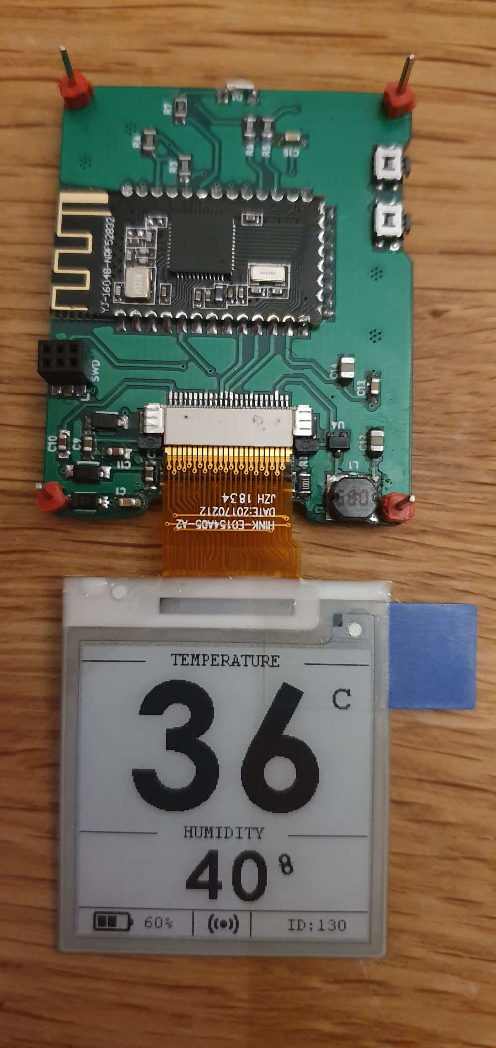
It sure is lonely in here... but finally SUCCESS!!!!
After days of googling and checking and rechecking the board for shorts, I found the problem. The 68uH was dead. Maybe damaged when soldering it. It did not conduct anything. After changing it to a new one, the display started working.
Any idea how battery can be at 60% on more or less fresh batteries... anyway, that is another problem.I still have one question, if anyone can chip in that would be great.
On the SWD connector it says, TX and RX, how do I use them?
Or really what I mean, how do you debug the device? I use a ST-Link V2, but I am not getting any COM-port so I cannot start the serial debugger. Is the TX/RX used for the serial debugging? Can I use ST-Link V2 for this or do I need a separate device?
I have tried to change the driver with ZADIG, but still no COM-port. As for now I have only connected 4 of the 6 pins in the SWD.Please @berkseo help me!
@magpern said in 💬 EFEKTA Temp&Hum sensor(ver. nRF52832 )+E-Ink display:
Any idea how battery can be at 60% on more or less fresh batteries... anyway, that is another problem.
Calculate the resistor divider. It is on the power Board. Perhaps you have mixed up resistors.
-
It sure is lonely in here... but finally SUCCESS!!!!
After days of googling and checking and rechecking the board for shorts, I found the problem. The 68uH was dead. Maybe damaged when soldering it. It did not conduct anything. After changing it to a new one, the display started working.
Any idea how battery can be at 60% on more or less fresh batteries... anyway, that is another problem.I still have one question, if anyone can chip in that would be great.
On the SWD connector it says, TX and RX, how do I use them?
Or really what I mean, how do you debug the device? I use a ST-Link V2, but I am not getting any COM-port so I cannot start the serial debugger. Is the TX/RX used for the serial debugging? Can I use ST-Link V2 for this or do I need a separate device?
I have tried to change the driver with ZADIG, but still no COM-port. As for now I have only connected 4 of the 6 pins in the SWD.Please @berkseo help me!
-
@magpern said in 💬 EFEKTA Temp&Hum sensor(ver. nRF52832 )+E-Ink display:
On the SWD connector it says, TX and RX, how do I use them?
Via TTL Converter. The program must be enabled in the debug.
-
It sure is lonely in here... but finally SUCCESS!!!!
After days of googling and checking and rechecking the board for shorts, I found the problem. The 68uH was dead. Maybe damaged when soldering it. It did not conduct anything. After changing it to a new one, the display started working.
Any idea how battery can be at 60% on more or less fresh batteries... anyway, that is another problem.I still have one question, if anyone can chip in that would be great.
On the SWD connector it says, TX and RX, how do I use them?
Or really what I mean, how do you debug the device? I use a ST-Link V2, but I am not getting any COM-port so I cannot start the serial debugger. Is the TX/RX used for the serial debugging? Can I use ST-Link V2 for this or do I need a separate device?
I have tried to change the driver with ZADIG, but still no COM-port. As for now I have only connected 4 of the 6 pins in the SWD.Please @berkseo help me!
@magpern said in 💬 EFEKTA Temp&Hum sensor(ver. nRF52832 )+E-Ink display:
Can I use ST-Link V2 for this or do I need a separate device?
You can connect the programmer and TTL Converter at the same time. You can also do so - https://translate.google.ru/translate?hl=&sl=ru&tl=en&u=https%3A%2F%2Fmysensors-rus.github.io%2Ftroubleshooting_on_Cortex_MCU_in_Arduino%2F